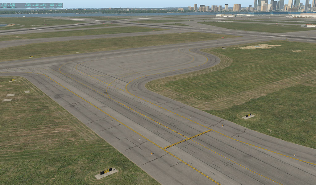
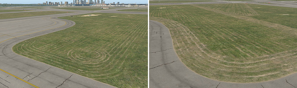
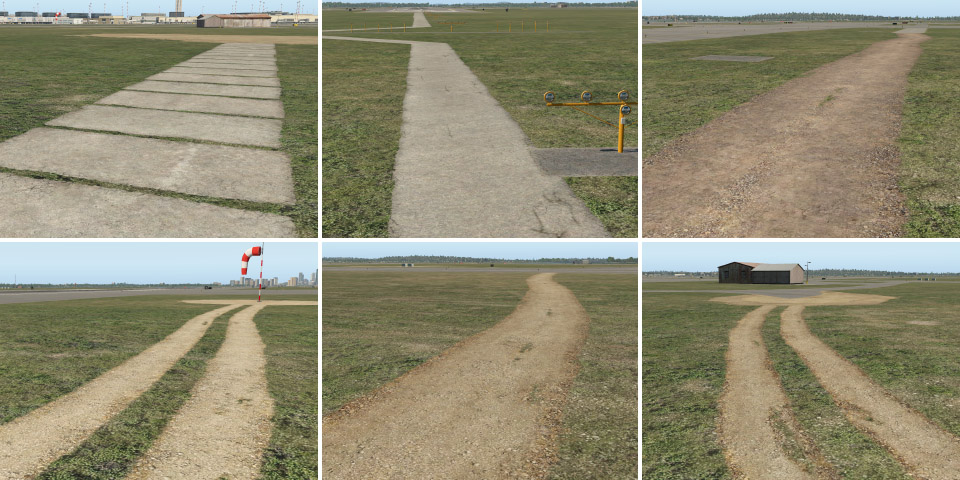
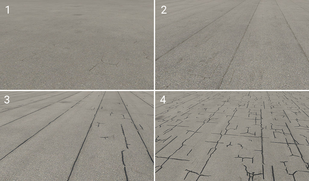
X-Plane 12 has a new set of textures and other art assets. The main idea behind this pack is the general improvement of airports – particularly the depiction of the ground surface. All features in this pack comprise POL, LIN, or simple OBJ assets, and all of them are “ground” oriented. Here is an example of what can be achieved:
The assets in this pack are divided into four categories:
lib/airport/ground/pavement
lib/airport/ground/pavement_FX
lib/airport/ground/terrain
lib/airport/ground/terrain_FX
We can understand these four categories as different groups of layers in the following order:
4 – pavement FX effects placed on, or snapped to paved surfaces (cracks, dirt, grunge, drains, etc.)
3 – pavement main hard surfaces (asphalt, concrete)
2 – terrain FX effects placed on, or snapped to natural surfaces (paths, grass patches, lawn tracks, etc.)
1 – terrain natural terrain (grass, desert, etc.)
A higher value means a higher priority of visibility. In other words, terrain FX won’t be visible through the pavement but the pavement FX over the grass will be shown. That means you can paint a dirt path across the border of asphalt, but you shouldn’t paint asphalt cracks across the border of grass.
1 – Terrain
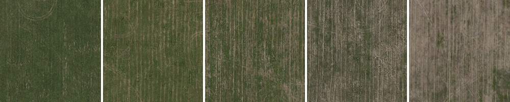
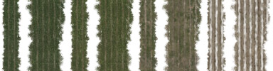
We have brand new textures and shaders for all basic airport terrains. The grass is completely new, the desert is new, and so on.
In addition, we have unique grass textures with lawn-mower tracks. This is a typical detail that can make the terrain look more realistic. These textures are directional so for better plausibility, it is very important to set the proper direction in WED polygons.
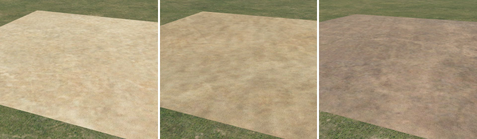
Next, we have textures for sand and soil. It can be useful for various patches in the grass.
2 – Terrain_FX
This is a group of effects that can be placed on top of natural terrain.
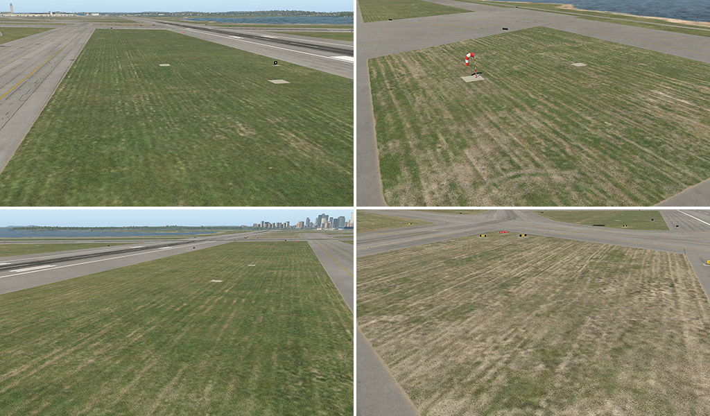
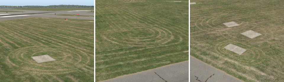
lawn_tracks
The lawn-mower tracks effect comes in different forms. POL (polygon) files have a similar visual effect to those above. This time, however, they are transparent and contain only the lawnmower tracks themselves. It can be placed on top of any type of underlying terrain (which can be handy for locations where nice green grass is not desired).
LIN (line or stripe) files are useful as a natural border between grass with a lawn-mower effect and surrounding areas. Typically these can form the natural shape of grass islands in between taxiways. We have various strips with corresponding colors of grass.
Typical use:
OBJ (object) files are mostly spots with a couple of tracks in circular form. These can be placed typically in corners, or under various things in the middle of the grass (like taxi signs).
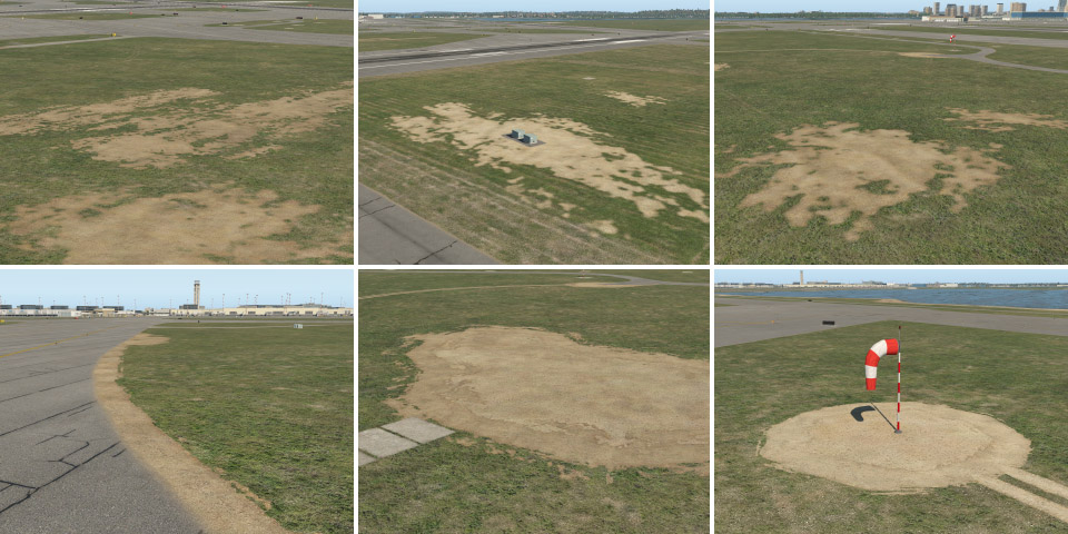
patches
Patches are available as single OBJ (various sizes and shapes) and as LIN (various widths). We also have all corresponding colors for basic terrain polygons – grass, dark grass, dry grass, light and dark sand, and soil. They’re useful for modeling various imperfections in basic terrain, spots, broken lawns, and so on. Also, these can be used along the edge of a taxiway, as an extension of the natural edges (see below).
paths
Path LIN are available in various widths and materials (concrete, sand, and soil).
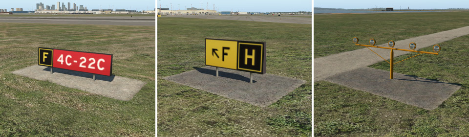
taxi_sign_base
These are paved bases for taxiway signs. Single OBJ are available in various sizes, and two colors (light and dark). If you can’t find the desired size for a certain situation, you can also use the LIN variant. These OBJ have an exception to the layer system described above. They render above the pavement so you can use them also on top of taxiways.
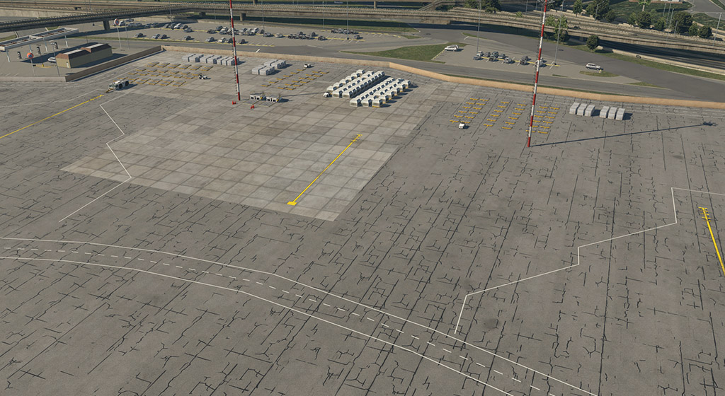
3 – Pavement
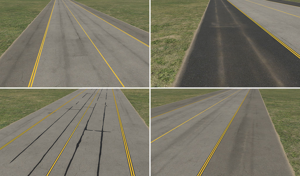
In X-Plane 12 we also have a brand new shader designed particularly for hard airport surfaces. Generally speaking, it can make better-looking asphalt and concrete, with less obvious texture repetitions over large areas (almost invisible repetitions).
asphalt_
Asphalt surfaces are available in five basic colors (light to dark).
Each color variant is available with four different effects:
1 – plain: this variant is omnidirectional. It is useful for specific situations (typically taxiway shoulders) in conjunction with various effects (see below).
2 – strips: this is probably the most common variant with typically visible strips.
3 – worn: same as (2), but a bit worn. Gaps between strips are sometimes cracked or patched.
4 – patched: highly worn, irregular, and more visible cracks.
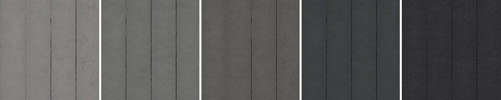
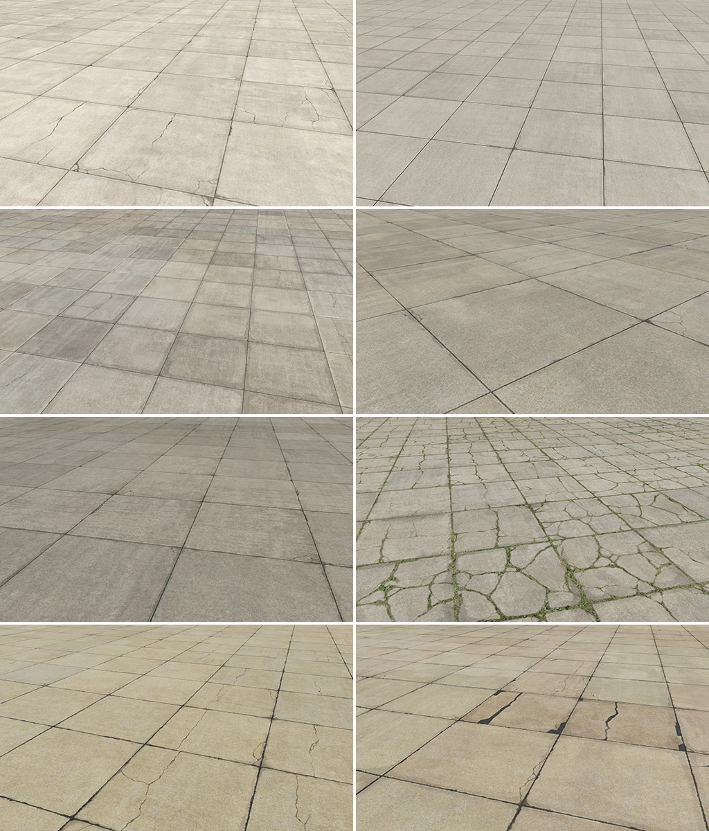
concrete_
Concrete doesn’t have a unified system like asphalt. We have three main colors (gray, light gray, and dark gray) but with slightly different effects for each of them. In addition, we also have the fourth color group which is tinted (red or yellowish). Here are some samples of the variants:
4 – Pavement_FX
This is a group of effects that can be placed on top of hard surfaces.
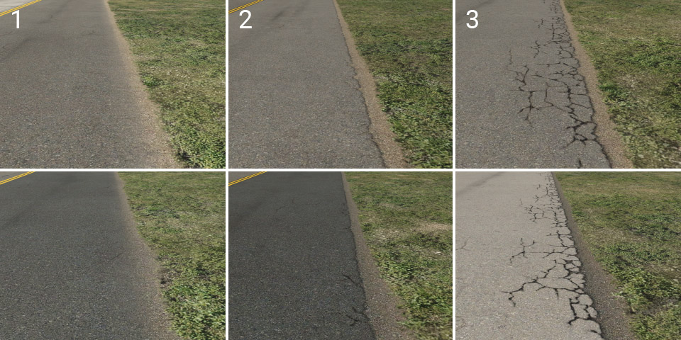
edges
Probably the most important asset. Edges are dividers of pavement and natural surrounding terrain. They are available in two colors (light and dark) and have three variants:
1 – soft: basic edge with a slight plastic effect. Suitable for most common situations, particularly for grass.
2 – elevated: pavement surface looks slightly elevated, and the edge is a little worn.
3 – cracked: a lot more cracked and worn.
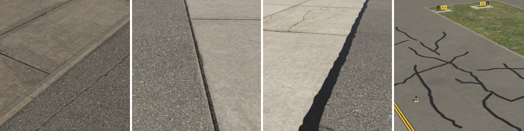
gaps
These are dividers of adjacent asphalt or concrete surfaces. A wide patch line can be used for manually painted large-scale cracks, however we recommend you do not repeat this small texture to cover large areas.
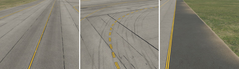
taxiway
Here we have four different types of taxiway structures. Imagine transparent strips, with the very subtle effect of dirt on asphalt. These were designed to be used in conjunction with the plain variant of asphalt. These are useful for curved segments of taxiways and particularly shoulders, and are available in different widths, which should roughly match the usual sizes of shoulders.
taxiway_cracks
Another kind of effect that is useful, especially for shoulders. Also available in different widths.
taxiway_dirt
In this group, you can find subtle dirt effects. Some are designed for placement along the centerline, others are for the edge of the taxiway.
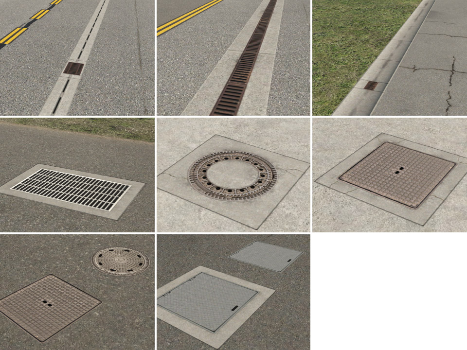
drains
Various drains and manhole cover lids.
General hint: most LIN effects have end caps. That means the line needs some minimum length. Any time you see an artifact (black rectangles), it is probably due to insufficient length of the line.
This document describes the X-Plane 12 material model – that is, how materials are authored and rendered for most solid 3-d elements in X-Plane. The material model is used for all OBJ 3-d models, aircraft, all scenery elements, and models inserted by plugins via the XPLM Instancing APIs.
X-Plane 12 Material Model Basics
X-Plane 12 uses an industry standard PBR “metalness” work-flow that matches the Disney/Unreal Engine 4 model, as well as a number of common tools including Substance Painter 2 and Blender’s “Principled BSDF” shading node. The goal is to provide close to WYSIWYG material authoring.
The main difference between X-Plane and other engines is in terms of what parameters can be controlled – some engines provide significantly more material parameters (at a higher rendering cost).
X-Plane lets you control:
Glossiness/roughness, either via a texture map or as a hard coded number in an art asset text file. We recommend using texture maps to control roughness/gloss.
Albedo/Base Color. The base color of the material is used as an albedo for dielectric materials, and as a reflection tint for metal colors – this is a fairly standard way to reuse a single color in metalness work-flows. In most X-Plane documentation this channel is simply called “albedo.”
Per pixel normal maps in tangent space using two channels.
An optional RGB/RGBA “emissive” overlay. This is calibrated to photometric units using a directive in the art asset text file. If an alpha channel is present, it will be added to the albedo alpha, which can be used for special effects but is generally not recommended.
Baked ambient occlusion for a small number of specialized art assets. (This feature is not currently available on OBJs, including plugins or aircraft, but may be added later.)
The model also lets you control in a texture map at most one of:
Base Reflectance (“F0”) – This is the amount of fresnel reflection a material exhibits when viewed with the camera perpendicular to the material (its least reflective position). Note that X-Plane uses F0 to control “metalness” as well but the two properties cannot be specified separately due to engine limitations – more details on this later.
Translucency – This parameter causes light on the back of a material to increase diffuse brightness, while limiting the diffuse brightness of the front of the material – it is meant for vegetation. When not in use, translucency defaults to zero.
Separate normal alpha – Can be used to create normal-map decals that affect terrain without drawing full materials. When not in use, normal alpha defaults to albedo alpha.
Metalness, Fresnel and F0
In a metalness PBR work-flow, “metalness” describes two material models:
Dialectrics: light is reflected off the surface of the material based on an angle of incidence/reflection; this reflection is not tinted. Remaining light is absorbed and re-emitted with tinting based on the albedo color; the albedo describes both how much light is absorbed/re-emitted and its spectral quantity. F0 defines how much light is reflected under the lowest reflected conditions; as the camera angle to the material becomes a grazing angle, reflection increases based on Fresnel’s law.
Metals: light is either reflected with tinting or completely absorbed. This is an approximation of actual metal optics, which require a much more complex fresnel equation. The goal of a metal work-flow is essentially to get tinted mirrors with variable but high reflectivity to make chrome/mirror parts look acceptable.
The metalness parameter of your material blends these two models, ideally producing intermediate materials that represent what you would get if your material contained specs of both dielectric paint and underlying metal.
X-Plane’s design limitation is that it does not provide separate channels for both Metalness and F0, for performance reasons. To work-around this, X-Plane works as follows:
When F0 in the material is in the range of 0.00 to 0.08, F0 is used as metalness and F0. This produces a nearly dielectric material for most useful F0 ranges, including:
F0 = 0.0 – this is an unrealistic mostly non-specular material. We recommend this for textures that represent complex 3-d self-shadowing phenomenon, like a terrain texture of grass.
F0 = 0.02 – 0.04, e.g. plastic, concrete, vinyl.
F0 = 0.06, e.g. glass.
Once the material F0 gets above 0.08, we use F0 for metalness, but clamp F0 to 0.08. This limits the amount of dielectric reflection the material exhibits in a hybrid material.
Once F0 is very high (e.g. 0.9 or higher, e.g basically metal) the light contributed from the dielectric part of the equation is extremely low and rendering should match tools.
Values for Material F0 When Not Using a Texture
When X-Plane’s normal/material map is in “metalness” mode, the blue channel is used as the material F0, giving you access to the full range of behaviors, including 0.0 (no specularity), 0.04 (reasonable dielectrics), 1.0 (pure reflective metals), and intermediate values.
In any other mode, X-Plane will pick a material F0 automatically based on the following rules:
If the material uses BLEND_GLASS mode and is attached to an aircraft in a glass lighting mode (one of interior glass, exterior glass, exterior rain glass or interior reflective glass) then F0 will be set to 0.06 to provide reasonable glass reflections.
Otherwise if the material uses a “translucency” mode normal map, F0 will be set to 0.0.
Otherwise if the material uses any other normal map (full RGBA, gloss-map only, etc.) F0 will be set to 0.04.
Otherwise the material uses no normal map. If its gloss is set > 0.0, F0 will be set to 0.04. This handles the case where a material is marked shiny in an OBJ but has no normal map – the result will be a glossy plastic-like material.
Otherwise the material uses no normal map and has the default maximum roughness; F0 will be set to 0.0 to create the illusion of additional self-shadowing.
Changes from X-Plane 11 Materials
X-Plane 11 introduced PBR materials; the X-Plane 12 model is an incremental update. The changes are:
X-Plane 12 renders “intermediate metals” (materials with F0/metalness between 0.25 and 0.75) in a manner compatible with SP2/Blender; X-Plane 11 would build these materials as if the dielectric part of the material had a super-high F0, resulting in a lot of extra specularity. The result would be that intermediate metals would be much brighter and more washed out than in standard authoring environments. If your model makes heavy use of intermediate metals you may need to change your albedo/re-bake your materials.
X-Plane 12 adds photometric calibration to emissive channels.
X-Plane 12 adds an optional translucent mode – translucency was effectively always off in X-Plane 11.
There are two concepts used throughout many of these APIs:
Flight ID: This is a unique identifier that persists for an entire flight. If you’re animating aircraft across API updates, you can use this to track which aircraft is which.
DSF: In X-Plane terminology, a DSF is a file that provides scenery for 1 degree latitude by 1 degree longitude. DSFs are named in latitude-longitude order for their southwest corner. Positive values are north or east, and negative values are south or west. So, for instance, +49-068 covers the scenery from 49 degrees north and 68 degrees west up to 50 degrees north and 67 degrees west.
Please note: At present, there is no metering on MMO API usage by third parties, but we ask that you be considerate of our server load and avoid making unnecessary requests. (For instance, if you start making frequent requests to get all 64,800 DSFs on the planet, we’ll have to cut you off!)
Gives the flight ID, latitude, longitude, elevation (in meters above mean sea level), and heading (in true degrees) of every aircraft online. This is limited to 3 decimal places in precision for latitude/longitude, and it only updates once per second. So, when your map gets zoomed in far enough, you’ll want to request data for the specific DSF you’re viewing.
//mmo.x-plane.com:4000/api/v1/dsf/[dsf_id]
Gives high-resolution data, updated about 10 times per second, for all aircraft in the DSF. (Keys are the same as in the world endpoint.)
The datarefs inside the sim/flightmodel2/wing/ are array indices for each wing on the plane. To understand how these array indices work, we need to consider how X-Plane manages “wings”.
Everything is a wing
In X-Plane, all airfoils (except for those that form propellers and pylons) are “wings”. This includes:
8 regular “wings”, each of which comes 4 pairs of left-right.
2 horizontal stabilizers, left and right.
2 vertical stabilizers (rudders).
Up to 20 “misc” wings.
For the purpose of this tech note we will use the term ‘wing’ to mean any one of these airfoils.
Each wing is assigned as being on the left or right side of the plane – this is how X-Plane knows whether a left roll moves the ailerons on this part up or down. Left right assignment is automatic for the regular wings and stabilizers, and manual in Plane-Maker for misc wings. (Vertical stabilizers are categorized as right wings, but in practice you should assume that ailerons on vertical stabilizers is a poor idea in X-plane — use a misc wing if you really need this, or tilt the horizontal stabilizers up like the cirrus jet).
Each wing may or may not be used in the actual plane, and if it is used, it is defined into a fixed number of slices running laterally across the airfoil. The airfoil properties are fixed for each wing, but the control surfaces can be set per slice. The control surface deflections and longitudinal geometry (e.g. how deep are the ailerons, where on the wing do the flaps sit) are set globally.
Now here’s where the array comes in: X-Plane calculates one control deflection for:
Each type of control (rudder 1, rudder 2, aileron 1, aileron 2) crossed by
Each actual existing wing
Individual control surfaces are then deflected on a per-slice basis by looking up the deflection for that part.
Two sets of everything
X-Plane features two sets of most controls (flaps, ailerons, etc) to allow for different maximum deflections and longitudinal positions. A number of other advanced control surface options can act differently on each set. For example, a plane might have a “small” set of ailerons on the far edge of the wing with small deflections and a small longitudinal size. A second set might be on a different part of the wing with larger deflections and larger longitudinal length.
use the control deflection array index that corresponds to the part of the wing you are really animating! This addresses several possible problems:
If the wing you animate is not on the same side of the plane as the dataref index you use, you could have an inverted animation.
If the wing is not present at all, the dataref might not move at all.
use the right TYPE of dataref. To animate an aileron that matches aileron 1 in position, use aileron1_deg, not aileron2_deg, yoke_roll, or any other “proxy”. By using the exact right dataref, you guarantee that the animation matches all of X-Plane’s behaviors.
Do not nest animations!!! X-Plane’s wing control deflection outputs in this dataref are the sum of all control surface activity. For example, if you have a plane that maps ailerons to spoilers at low speed and speed brakes to spoilers, then when both are in effect the spoiler1_deg dataref will be the sum of all deflections. You do not need to nest animations to add up multiple control influences.
Use the special controls in PlaneMaker to achieve effects like roll spoilers – this way you can follow the rule above.
Custom Control Deflections Via Plugins
X-plane can write different controls deflections into different wings, if certain hydraulic system failures or other conditions apply. It is possible for plugins to override sim/operation/override/override_control_surfaces. At this point a large number of datarefs are under plugin control including the wing offsets. In this scenario, a single wing (but not a slice of a wing) could have a deflection that varies from all other parts.
In this way, it is possible to have up to 8 different speed-brake panel deployments (for example) on a single (4-part) airliner wing: a plugin would simply write a different value to each of speedbrake1_deg and speedbrake2_deg for each of the 4 left wings.
In this case it is particularly important for the animated model to match the right array index.
X-Plane 11.36 adds a new parameter to the steering/castor setup for nose and tailwheels, that makes it possible to add a castoring range onto a steered wheel.
Up and including to 11.35, a wheel could be one of three things:
Fixed: a main gear wheel is usually fixed and does not steer.
Steered: a nose or tail wheel that is actuated with a tiller or rudder linkage is steered up to a certain angle, where the maximum angle can be dependent on the speed.
Free Castoring: on many taildraggers and also some modern tricycle aircraft like the Cirrus SR22 or Columbia 400 there is no wheel steering at all, they instead rely on rudder and differential braking to steer on the ground, with the wheel just trailing.
11.36 adds another option, that is commonly found on aircraft like the C152, C172, etc.:
Non-rigid steering with castoring range: The wheel can be steered through rudder linkage up to a (small) deflection angle. By using differential brakes, the plane can turn tighter, in which case the wheel deflects further than it would from rudder linkage alone.
The new parameter is found in Plane Maker as: “castor limit (deg) This is the maximum amount that the nosewheel or tailwheel of the aircraft can steer from full rudder deflection and pulling the plane into a turn with differential brake. Enter zero if the nose wheel does not steer more than the rudder-linked values or the tail wheel is not limited in castoring at all.”
That means, the nose wheel steering limit (fast and slow) for the 172 is 10 degrees, as can be found in the TCDS of the aircraft (or the POH).
However, the new castor limit is 45 degrees.
Now what happens is:
With the rudder pedal, the nosewheel is deflected with the rudder up to 10 degrees left or right.
At 10 degrees deflection, differential braking can be used. If the differential braking causes a tighter turn, the wheel will turn in, following the steering impulse from the differential braking, and allow a tighter turn without slipping the nose wheel, to a maximum of the “castor limit” of 45 degrees.
While in this situation, relaxing the differential braking will not immediately cause the wheel to spring back to 10 degrees. It will come out of this deflection depending on the forces that turn the plane. So you can get the plane out of the turn by relaxing the rudder pedal deflection – once the rudder is not hard over one way anymore, the springs will pull on the wheel once again, or you can increase thrust, apply brakes or even diff-brake in the other direction.
Note that all of that also works on a tailwheel as well.
For users without brake pedal axes, the “auto-toe brakes” follows the existing “left and right brake power to help with steering (if no rudder pedals present)” setting. This way, the toe brakes can be activated on full rudder deflection, leading to the tighter turn naturally.
If that parameter is 0, no auto-toe braking happens. The parameter is ignored if the user has hardware pedals with independent toe-brake axes.
Do not use the “tailwheel spring force” parameter on anything but a tailwheel any more. In the past, you could abuse it to get auto toe-braking, but you can get this explicitly with the toe brake parameter. The tailwheel spring force has unintended side effects if used on planes that aren’t tail-wheel configuration, so it must be 0 unless you actually have a taildragger with a spring steering.
Use the deflection time parameter to model the delay introduced into the nosewheel steering by a non-rigid linkage (bungee cords in a Cessna). Wheel deflection follows the rudder (or tiller) deflection with the speed constant “nosewheel steering full deflection time (sec)”. This can be used for a hydraulic actuator that takes time, or the bungees pulling the wheel around rather than a fixed linkage. That time would be 0 in a Piper with fixed linkage.
If the castor limit is 0 (which it is for existing planes not modified in Plane Maker 11.36) the nosewheel steering will work as it did before, so it is suitable for Airliners or Pipers.
If the castor limit is non-zero and applied to a castoring wheel (which has no steering angle) it will limit how far the wheel can be deflected by castoring. While not particularly useful for tail-wheels, this is useful for castoring nose-wheels, like on a Grumman or Cirrus.
X-Plane 11.35 comes with a few additions to the fuel system, in order to make it more flexible for third-party developers, hopefully removing the need to override it in many cases.
Fuel-arm for oddly shaped tanks
New to X-Plane 11.35 is the possibility to enter two longitudinal arms for the fuel tank position, one for empty and for full (by default, X-Plane just copies the arm of the empty tank to the full tank). Normally, the moment of the fuel in a tank is expressed by the arm of the fuel tank, multiplied by the fuel weight. On some planes the arm itself changes as fuel is used from an oddly-shaped tank, and the moment changes by both the weight difference and the arm difference. King Airs are notable examples of where the fuel arm changes with fuel level. By setting a different arm for the full tank, X-Plane will accurate simulate the mass and balance effect of the fuel in such tank arrangements.
Fuel pump pressure per tank setting
This is a setting in Plane Maker that has existed for a long time, even before X-Plane 11. By giving tanks individual fuel pump pressures, designers can control the order in which X-Plane is going to empty the tanks.
When multiple tanks are available according to the fuel selector setting (e.g. fuel selector to “left” with multiple tanks on the left side), the pump with the highest pressure will supply the fuel until its tank is empty. This is comparable to the system of override pumps, found for example on a 747.
New to X-Plane 11.35 is the ability to change fuel pump pressure at run-time via a dataref, allowing precise control over which tanks will be providing fuel at any given time.
For example, on a 737 the center tank pumps provide a higher pressure than the wing tanks, therefore, the center tank is first emptied before any fuel is taken from the wing tanks.
Firewall shutoff valves
Commands for the left and right firewall shutoff valves (sim/fuel/fuel_firewall_valve_lft_open, etc.) have existed in X-Plane since before version 11. X-Plane 11.35 adds data refs, too. Use them to your advantage.
Fuel tank Role – NEW to X-Plane 11.35
In addition to the pressure, a tank can now be assigned a role:
Normal – this is the default and retains the logic directed by the pump pressure
Feeder – this is a tank that feeds an engine and is always kept full from the other tanks on this side with an automatic transfer pump. If a feeder tank exists, the engine will only get its fuel from the feeder, while other tanks can provide fuel to keep the feeder full.
Aux – this is the opposite of a feeder tank: it cannot feed the engine directly, but it is used to keep the feeder tank full as long as possible with the automatic transfer pump
Trim – like an AUX tank, but never automatically transferred to or from. You need to use “fuel transfer from” or “fuel transfer to” to change this tank’s fuel level
Note that this is not necessarily what the POH calls the tank! For example, in a Cessna Golden Eagle the tip tank is called “Aux” tank, but it can be selected to feed the engine directly, with the fuel selector. Therefore, it is not an “Aux” tank for X-Plane, since that would mean it is not selectable to feed the engine directly. In order to model the preference for main or aux tank, one would use the new pressure dataref.
Note that a stabilizer tank on a 767-400ERX or a 747-400 is not a “trim” tank. Despite being in the stabilizer, it contains useable fuel for both in flight or on the ground. On the other hand, Tank 11 in a Concorde is a “trim” tank, because it cannot be filled on the ground without the plane tipping over!
Automatic transfer pumps
With tanks on each side of the airplane being configured as Feeder and Aux, the transfer pump on each side will keep the feeder tank full until the aux tank runs dry, and then turn on the “NO TRANSFER” warning light.
A feeder pump can be operated in automatic mode (where you can specify a difference that triggers the pump to operate) or override mode, where the pump runs continuously.
Automatic cross feed
This is also new for 11.35. The common crossfeed manifold allows an electric boost pump to supply pressure to the engine on the other side and thus cross-feed an engine if the on-side boost pump has failed.
If the cross feed is operated in auto mode, the same limit value that triggers the low fuel pressure annunciator will also trigger the crossfeed valve. In manual mode, the crossfeed valve can be open or closed.
Datarefs
sim/cockpit2/fuel/transfer_pump_left	int	y	enum	Transfer from left AUXes to left FEEDers: 0: Off, 1: Auto, 2: On/Override
sim/cockpit2/fuel/transfer_pump_right	int	y	enum	Transfer from right AUXes to right FEEDers: 0: Off, 1: Auto, 2: On/Override
sim/cockpit2/fuel/transfer_pump_activation	float	y	kg	Automatically transfer from AUXes to FEEDers in auto mode when feeder has more than X kg left to full
sim/cockpit2/fuel/fuel_level_indicated_left	float	n	kg	Indicated fuel level left, shows total or only nacelle tanks depending if user is holding down the aux-tank button.
sim/cockpit2/fuel/fuel_level_indicated_right	float	n	kg	Indicated fuel level right, shows total or only nacelle tanks depending if user is holding down the aux-tank button.
sim/cockpit2/fuel/firewall_closed_left	int	y	boolean	Firewall valve closed, left
sim/cockpit2/fuel/firewall_closed_right	int	y	boolean	Firewall valve closed, right
sim/cockpit2/fuel/auto_crossfeed	int	y	enum	0=Off 1=Auto 2=On - If fuel pressure on one side is low, due to fuel pump failure for example, cross-feed is opened to allow one pump to supply pressure to both engines.
sim/cockpit2/fuel/no_transfer_left	int	n	boolean	Warning light, will illuminate when transfer from aux to feeder is requested, but aux tank is empty
sim/cockpit2/fuel/no_transfer_right	int	n	boolean	Warning light, will illuminate when transfer from aux to feeder is requested, but aux tank is empty
sim/cockpit2/fuel/transfer_test	int	y	boolean	Transfer test switch. 0 = normal, -1 = test left, +1 = test right
sim/cockpit2/fuel/tank_pump_pressure_psi	float[9]	y	psi	Pressure generated by the fuel pump per tank. If multiple tanks are accesible per the fuel selector, fuel will be consumed from the tanks in order of pump pressure
Commands
"sim/fuel/left_xfer_override" ,"Aux to feeder transfer left override."
"sim/fuel/left_xfer_on" ,"Aux to feeder transfer left on."
"sim/fuel/left_xfer_off" ,"Aux to feeder transfer left off."
"sim/fuel/left_xfer_up" ,"Aux to feeder transfer left off->on->overide."
"sim/fuel/left_xfer_dn" ,"Aux to feeder transfer left override->on->off."
"sim/fuel/right_xfer_override" ,"Aux to feeder transfer right override."
"sim/fuel/right_xfer_on" ,"Aux to feeder transfer right on."
"sim/fuel/right_xfer_off" ,"Aux to feeder transfer right off."
"sim/fuel/right_xfer_up" ,"Aux to feeder transfer right off->on->overide."
"sim/fuel/right_xfer_dn" ,"Aux to feeder transfer right override->on->off."
"sim/fuel/left_xfer_test" ,"Aux to feeder transfer test left."
"sim/fuel/right_xfer_test" ,"Aux to feeder transfer test right.
"sim/fuel/auto_crossfeed_on_open","Crossfeed valve open."
"sim/fuel/auto_crossfeed_auto" ,"Open crossfeed valve when pressure difference detected."
"sim/fuel/auto_crossfeed_off" ,"Close crossfeed valve and turn off auto-crossfeed."
"sim/fuel/auto_crossfeed_up" ,"Auto-crossfeed off->auto->on."
"sim/fuel/auto_crossfeed_down" ,"Auto-crossfeed on->auto->off."
We have always had independent left and right fuel selectors for twins as datarefs, but not as commands. These are the new commands:
X-Plane 11.35’s bleed air system is an extension of the earlier X-Plane bleed air system, designed both for versatility and compatibility.
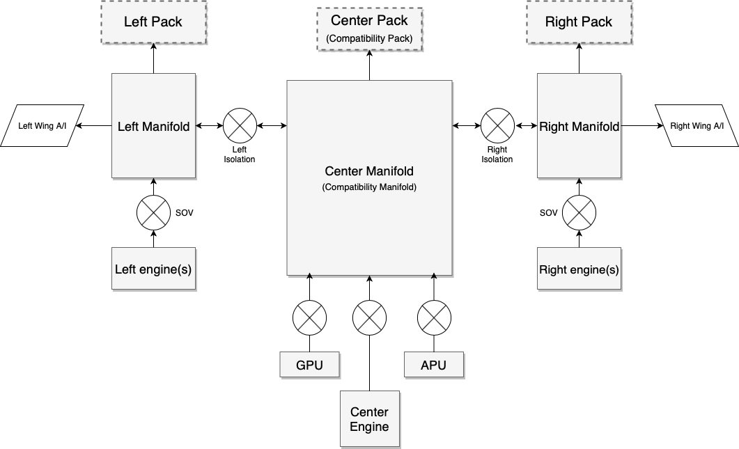
At the center of the new bleed air system is the center manifold which serves as the backward-compatible portion that is used by all airplanes, designed to provide basic bleed air and pressurization capabilities for existing aircraft.
Aircraft modernized for X-Plane 11.35 and later can make use of the left and right extensions of the bleed air system, and opt to use 1, 2 or 3 air conditioning and pressurization packs.
The system design is best understood with this diagram:
The center components provided for compatibility are clearly marked.
X-Plane legacy aircraft know only one pressurization pack, and one selector that selects the sources for this pack: left hand side of the aircraft, right hand side of the aircraft, and APU. Both APU and the center engine in a one- or three-engined plane are considered to be providing air from the center of the aircraft.
New to X-Plane 11.35 are: GPU bleed, left pack, right pack, wing-anti ice supply, and per-engine shut-off valves.
Another way to understand the system is as a Lancair (legacy X-Plane) overlaid with a King Air overlaid with a 747 – you will then understand how to design many more aircraft types with it:
1. Single-engine plane (Lancair Evolution or similar)
The center pack is the single source of cabin pressure. Packs L and R are always off because they don’t exist.
The bleed selector doesn’t care for left or right or both, the isolation valves have no function, the only available settings are: Bleed “off” meaning engine shut-off valve off and Bleed “on” (any of L, R or BOTH) meaning engine shut-off valve on. Bleed “auto” adds APU valve on (the single engine plane most likely doesn’t have an APU, but if it has, it would work), GPU adds GPU off or on. There’s only one duct, and only one available pressurization pack, center.
2. Two-engine plane with single pressurization (old King Air or similar)
The center duct supplies the one center pack that provides air to the cabin. The pack can be fed from the left engine, the right engine, or both. The bleed air mode thus maps to the isolation valves: left bleed air means left isol valve open, right bleed means right isol valve open, bleed both or auto mean both isolation valves open. If an APU was installed, it would feed into the center duct regardless of the isolation valve settings, controlled by the APU valve, just like the GPU.
3. Four-engine plane (resembling 747)
The system operates exactly like a 747 would: Three packs are available, per-engine SOVs, APU SOV and GPU SOV and two isolation valves work exactly like you’d expect when comparing the above graphic to the schematic of a 747.
4. Twin engine plane (737, A320, CRJ, ERJ, etc.):
Here’s where it gets interesting. For correct operation, one must turn off the legacy center pack and never turn it on again. That must be done actively by script or plugin, since X-Plane will never turn off the center pack – that would break existing aircraft!
The plugin can turn pack C off and pretend it doesn’t exist.
One can then turn on pack L and pack R as per the pack switches.
One can turn off or on the per-engine SOVs as per the engine switches.
Now the only remaining switch is the (single) isolation valve found in such aircraft.
This is where it gets airplane specific and one needs to look at a diagram for the specific airplane: Look up whether the APU and GPU feed into the left or the right from the single isolation valve. For the sake of explanation, let’s assume we are looking at the 737, where the APU feeds into the left duct and GPU feeds into the right duct.
For operation with the APU, the isolation happens to the right of the APU. That is, the isolation valve of the 737 with APU feed is the ISOL R valve in the X-Plane system (and ISOL L is always open). This way, center and left duct belong together, and are fed by left engine and APU. To the right of the isolation valve is the right engine.
For operation on GPU, the isolation happens to the left of the GPU! That is, the isolation valve of the 737 in GPU feed is now the ISOL L valve in the X-Plane system (and ISOL R is always open). This way, the left engine is to the left of the isolation, and GPU and right engine are to the right of the isolation.
Note that GPU and APU can never feed together – in real planes, the APU load control valve is also a one-way check valve. If theAPU valve was commanded to open while the system is pressurized from the GPU, it simply wouldn’t open. In that case, the system operates as GPU-fed until the GPU is off.
5. Twin engine plane (McDonnell-Douglas)
For a plane like the MD-80, which has two isolation valves, operation becomes very simple:
The center pack is turned off (by script or plugin) and never turned on again.
Pack L and pack R are turned on as per the Air Cond Cockpit and Air Cond Shutoff switches.
One can then turn off or on the per-engine SOVs as per the supply switches and fire handles. Both pulling a fire handle or turning off a supply switch should close the engine valve.
The left and right isolation valves separate the side systems with their respective packs from the center duct, into which the APU and GPU feed. These valves are thus direct mappings between X-Plane and and the MD-8x cockpit.
6. Three engined-planes
Because three-engined planes are very dissimilar in design between a 727, DC-10 or Tu-154, X-Plane makes no effort to resemble either – it is expected that custom plugin code will be needed to accurately simulate a three-engine plane.
Electrical power consumption
Having covered the pneumatic side of the system, let’s look at the electric side.
X-Plane has one electrical consumer for “HVAC” that until X-Plane 11.34 could not be controlled via datarefs or commands. From X-Plane 11.35 onwards, the following electrical loads are simulated with the various components of the system:
AC compressor and fan take 100% of the amp load that is specified
Fan only takes 10% of the amp load that is specified
Fan and heater in flight mode take 100% of the amp load that is specified
Fan and heater in ground mode take 200% of the amp load that is specified
Note that most of this is only relevant to GA planes, not airliners. Airliners do neither have electrical AC compressors nor electric heaters. Heat is supplied by the bleed air alone, it comes out of the engines so hot that it does not need to be heated. The cooling is provided by an air cycle machine driven by bleed air pressure itself, so it does not need lots of electrical power to run the air conditioning to cool it down.
So in an airliner, one would only ever use the fan function, so in Plane Maker, the amp load of the fan times 10 needs to be specified for the whole system, since we are never going to use the remaining 90%.
In a GA plane, the AC compressor is driven by electrical power, so using it will put you in the situation where X-Plane will use 100% of the specified amps.
Some turboprop planes, notably the King Airs and Cheyennes, have not enough heat from the engines to sustain cabin heating alone, so they use an electric heater grid consisting of 8 grids at 36amps each (that is the value for a King Air 90), four of them operate in flight, and an additional four can be activated on the ground when enough power is supplied either by both generators running, or by a GPU. That “ground max” heat setting will double the power consumption, as explained.
Datarefs
sim/cockpit2/pressurization/actuators/air_cond_on int y boolean Electrical air conditioning compressor on, consuming all the amps of rel_HVAC - not needed on airplanes with air cycle machines that drive the air conditioner off the bleed air power itself.
sim/cockpit2/pressurization/actuators/heater_on int y boolean Electrical heater grid on, 0 = off, 1 = flight max (consumes rel_HVAC amps), 2 = ground max (consumes 2x rel_HVAC amps, turned off by weight-off-wheels) - not needed on airplanes that are using hot bleed air and have no heaters
sim/cockpit2/pressurization/actuators/fan_setting int y enum Electric fan (vent blower) setting, consuming 0.1 of rel_HVAVC amps when running. 0 = Auto (Runs whenever air_cond_on or heater_on is on), 1 = Low, 2 = High
sim/cockpit2/bleedair/actuators/engine_bleed_sov int[8] y boolean Engine bleed air shut off valve, close or open
sim/cockpit2/bleedair/actuators/apu_bleed int y boolean APU bleed air valve, close or open. APU must be running at 100%N1 to provide bleed air
sim/cockpit2/bleedair/actuators/gpu_bleed int y boolean GPU bleed air valve, close or open. A GPU is supposed to be always available.
sim/cockpit2/bleedair/actuators/isol_valve_left int y boolean Isolation Valve for left duct, close or open. This separates all engines on the left side of the plane, the left wing, and the left pack from the rest of the system
sim/cockpit2/bleedair/actuators/isol_valve_right int y boolean Isolation Valve for right duct, close or open. This separates all engines on the right side of the plane, the right wing, and the right pack from the rest of the system
sim/cockpit2/bleedair/actuators/pack_left int y boolean Left pressurization pack, off or on. The left pack is supplied from the left side of the plane or through the left isolation valve and only available for airplanes made for 11.35 or newer
sim/cockpit2/bleedair/actuators/pack_center int y boolean Center pressurization pack, off or on. The center pack is supplied from center duct, which can be supplied from a center engine, APU, GPU, or, via the isolation valves, the left and/or right ducts. This pack is the only pack available for airplanes made for X-Plane 11.33 or older
sim/cockpit2/bleedair/actuators/pack_right int y boolean Right pressurization pack, off or on. The right pack is supplied from the right side of the plane or through the right isolation valve and only available for airplanes made for 11.35 or newer
sim/cockpit2/bleedair/indicators/bleed_available_left float n ratio Bleed air available in the left duct, which can come from left engines or through the left isolation valve.
sim/cockpit2/bleedair/indicators/bleed_available_center float n ratio Bleed air available in the center duct, which can come from a center engine, APU, GPU, or, via the isolation valves, the left and/or right ducts.
sim/cockpit2/bleedair/indicators/bleed_available_right float n ratio Bleed air available in the right duct, which can come from right engines or through the right isolation valve.
sim/cockpit2/bleedair/indicators/engine_loss_from_bleed_air_ratio float[8] y ratio Bleed air being sapped from the engine, stealing efficiency from the compressor. Writeable only with override_pressurization set
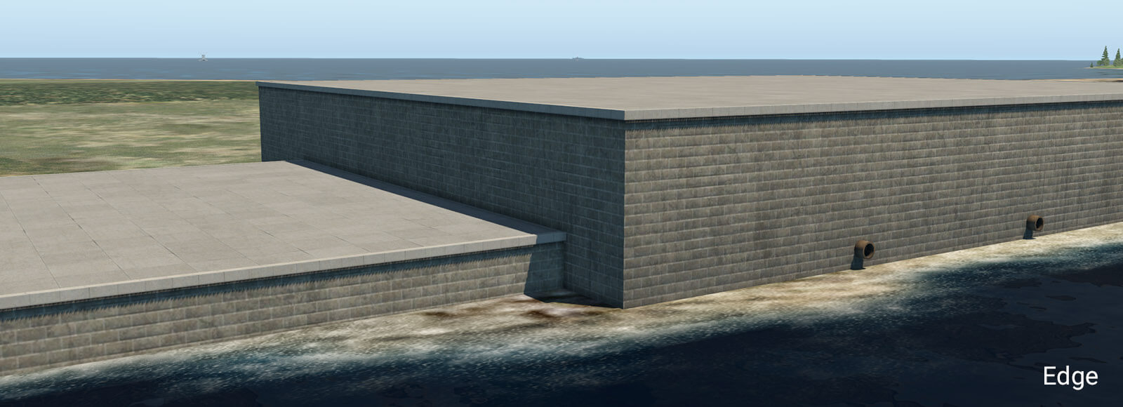
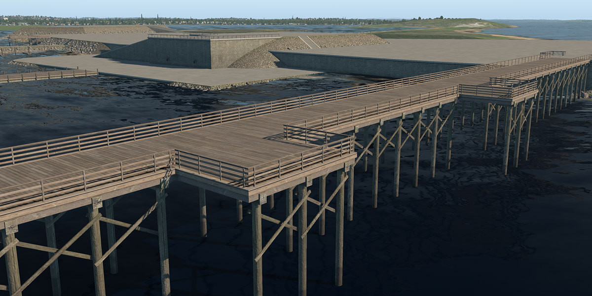
X-Plane 11.30 introduces new facades and objects for the creation of embankments, sea-walls, piers, and docks. These can be found in the WED library hierarchy at: “lib/constructions/piers“.
Key components are special facades with various wall types for specific usage (similar to the ‘Terminal kit’ introduced in an earlier release). This facade is used in the main for the creation of ship ports, quays, river banks and sea-walls.
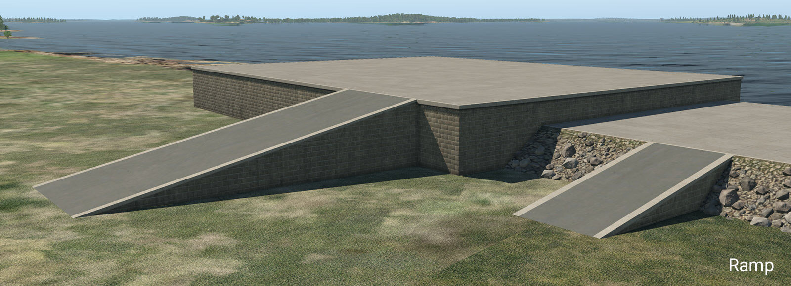
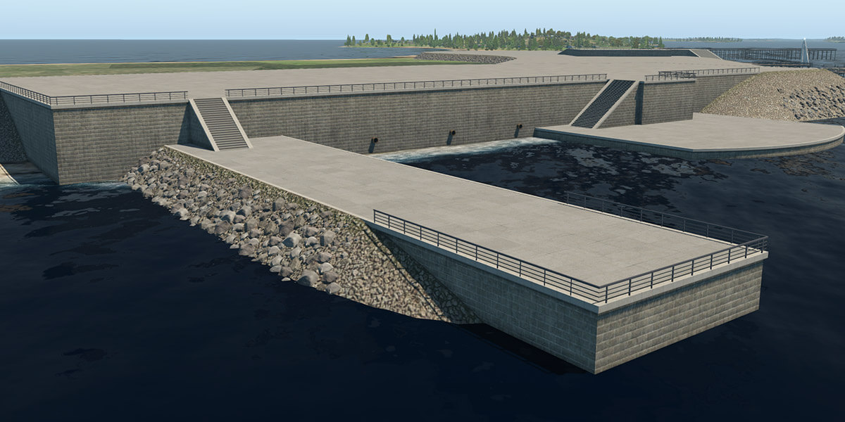
embankment_01.fac
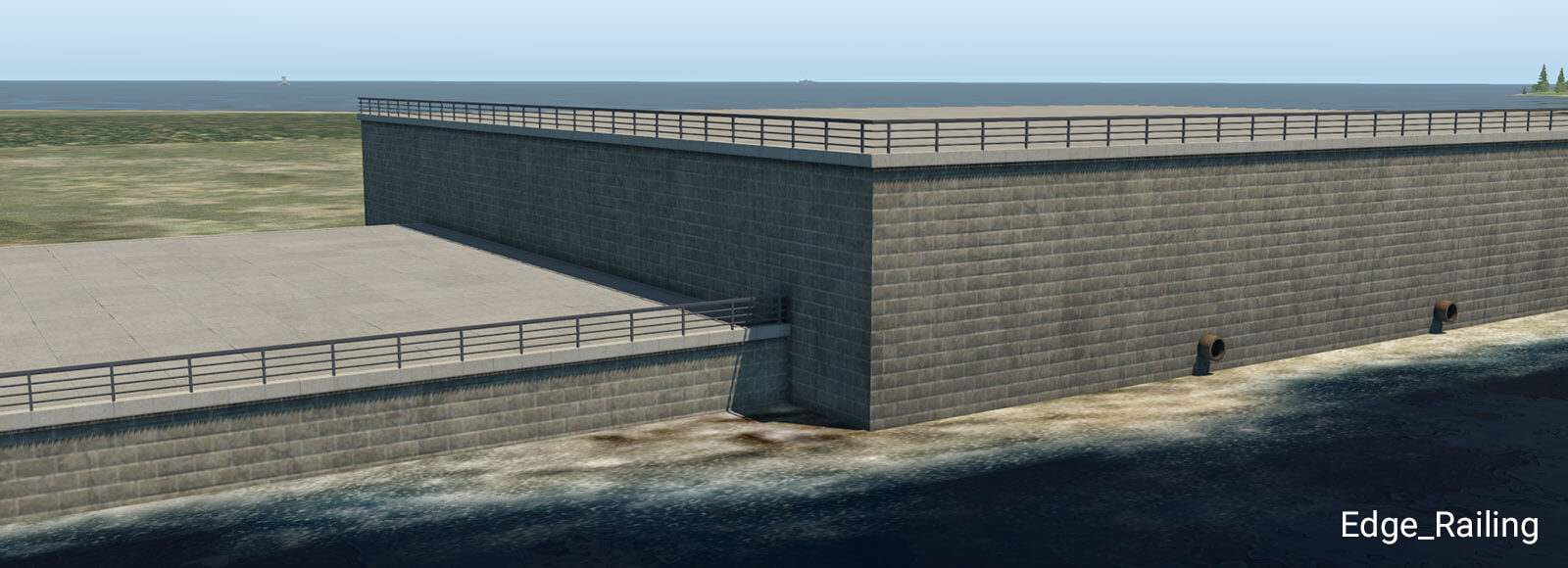
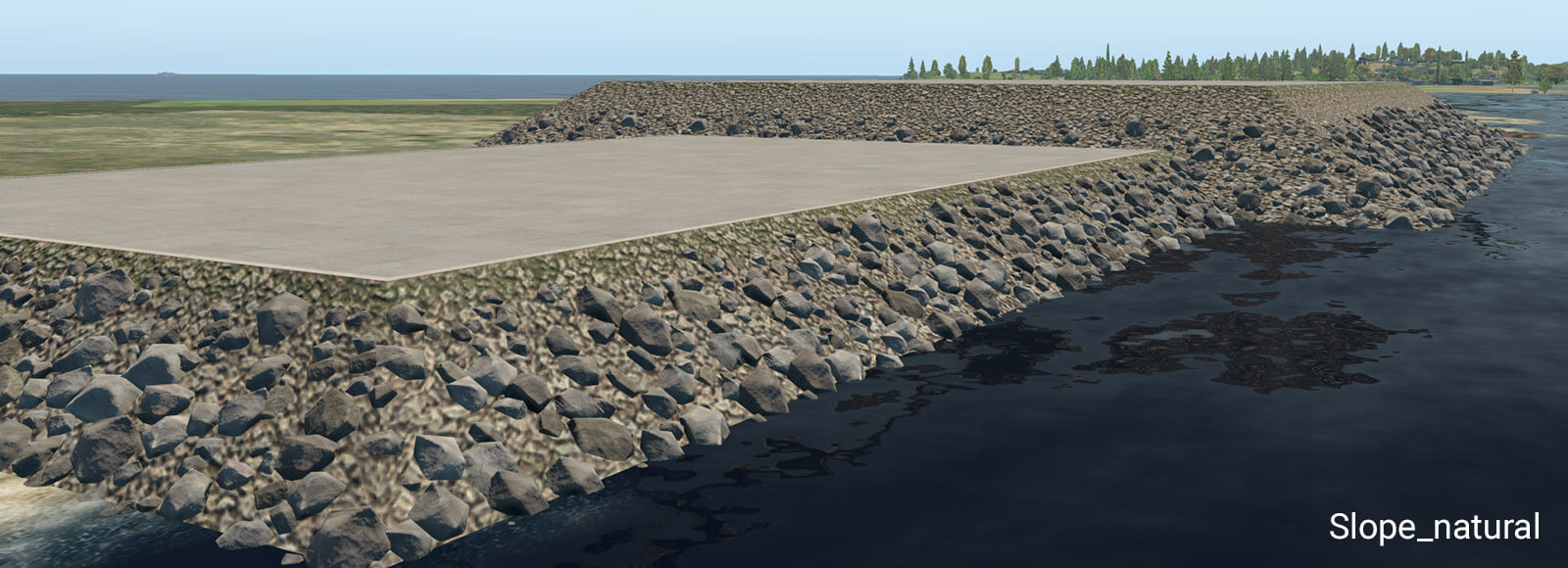
This facade can form a typical stone embankment with vertical and sloped walls. It is designed for height ranges between one and ten meters, with a one-meter step. This facade must be placed as a closed polygon, with manually selected walls. Due to the nature of the facade system, there are some design limitations. The basic vertical wall works without any specific limitations. However, sloped walls (like natural slope, stairs or ramp) don’t work very well in conjunction with sharp angles at corners. When the corner angle is 90 degrees and more, there is an obvious distortion in UV texture mapping. This may look silly, especially with the greater height so try to avoid very sharp corner angles when using these walls. For the same reason, it is not recommended to switch between vertical and sloped walls at corners. This works best with straight polygon segments.
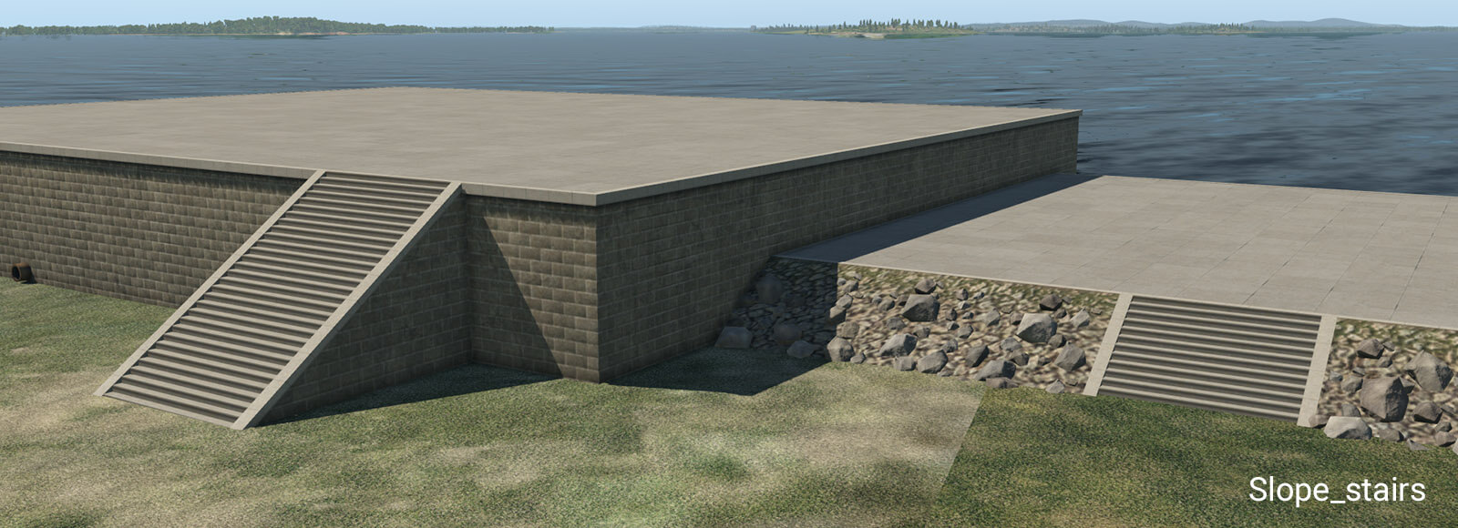
Stairs have exactly the same angle as the natural slope so they can be seamlessly placed in between sloped walls.
The ramp is designed for straight segments. Do not use it at sharp corners, because it has very obvious UV texture deformations due to its shape.
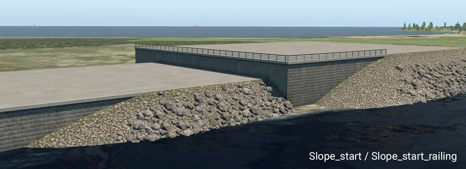
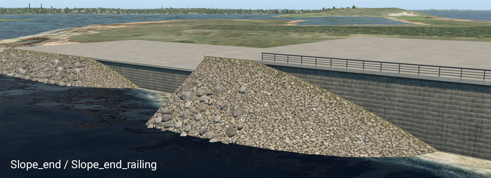
These pairs of transition segments are useful when you need a smooth transition between the vertical wall and natural slope. They work best in straight segments also. Note they require some length to be shown properly. A safe length is about 32 meters. However, you can make the transition segment much longer. If you do so, “Slope_start” will appear at the very beginning of that segment, and “Slope_end” will appear at the very end.
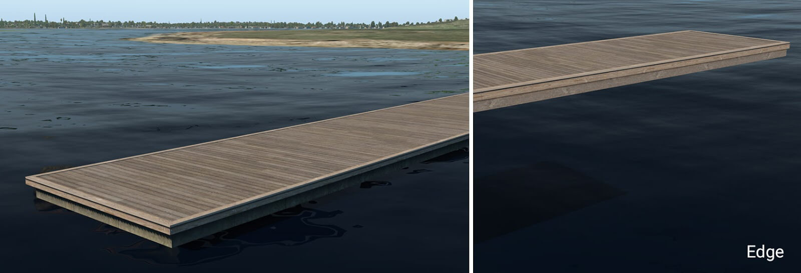
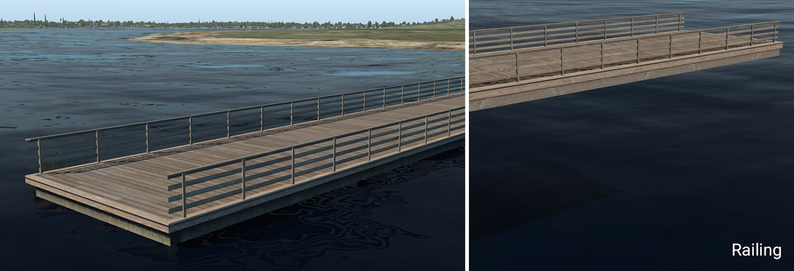
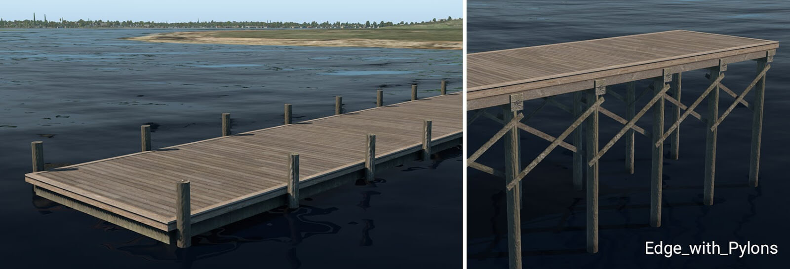
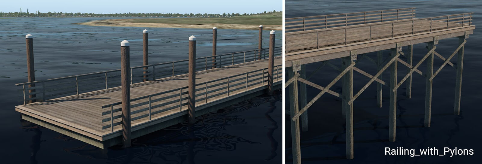
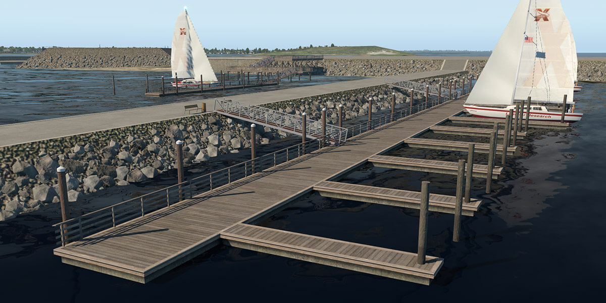
pier_wooden_01.fac
This facade is used in the main for the creation of typical wooden piers or docks. It works for the same height ranges (1 to 10) plus an additional 0.6 meters. This is because 60 cm is a typical height for small floating piers. The two lowest height levels (0.6 and 1 meter) look like a floating pier and the rest form a pier on pylons.
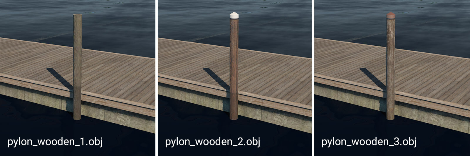
pylon_wooden_X.obj
These pylons can be placed manually. They are useful in combination with floating wooden piers. For more convenient placement, they are also available as strings: “pylons_row_wooden_X.str”.
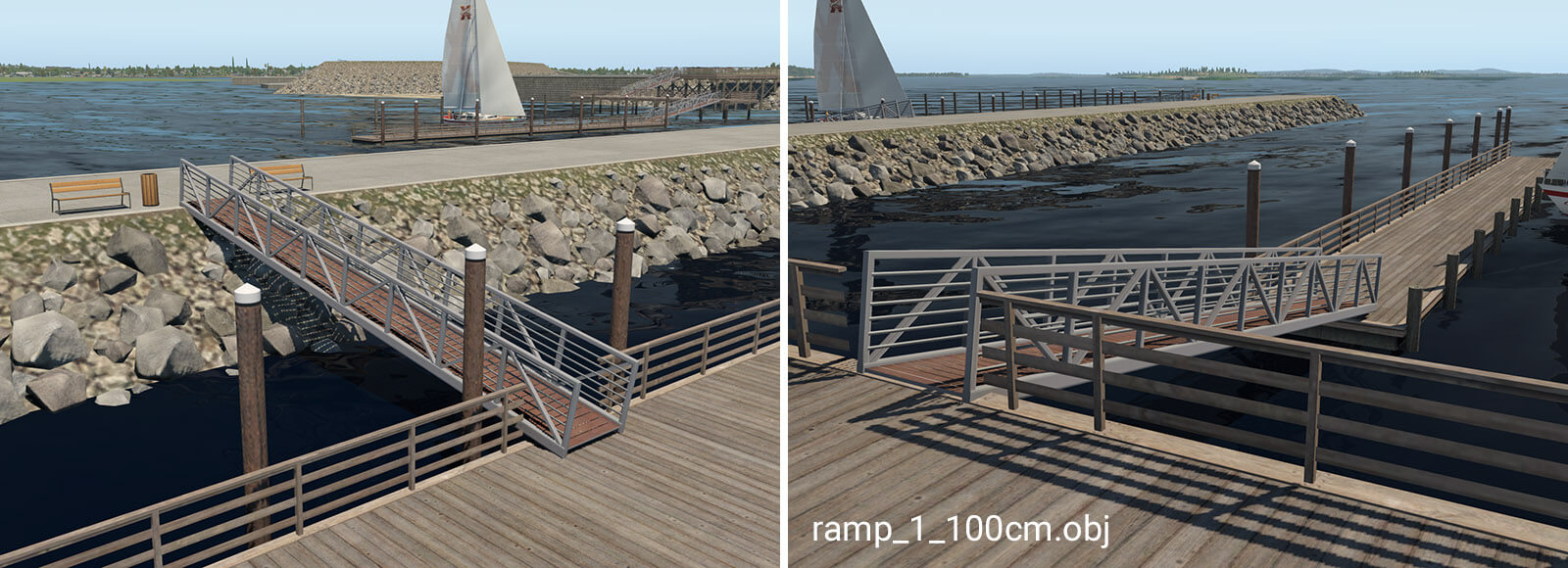
ramp_1_100cm.obj
The ramp object is available in seven different variants. It is designed for connections between levels with differing heights. The numbers in the name mean the total height of the ramp (e.g. ramp_1_240cm is 2.4 meters high). This object is available with heights of 140, 240 and 340 which is necessary in conjunction with the special 60cm pier. For proper placement of the ramp above the pier, artists must use the ‘Set MSL’ feature in WED, with the appropriate altitude above sea level.
X-Plane has two vacuum systems per airplane, one for the pilot side instruments and one for the copilot side instruments. By default, the suction is generated by pumps driven by the engine, so it is dependent on your engine RPM.
Two additional sources of vacuum are available in X-Plane 11.30:
an aircraft can be equipped with a venturi tube instead, a very simple system found on vintage aircraft, where the suction is generated by the air going through a venturi tube placed on the fuselage, so it is effected by airspeed and propeller slipstream
an electric backup pump that can be switched on and provide suction when the engine pumps fail
Engine-driven vacuum pumps – single engine
X-Plane simulates the vacuum system for physical vacuum-driven gyros as follows:
There are two vacuum systems: One for the pilot instruments, one for the copilot instruments.
If you have no copilot instruments, then no problem: The second vacuum system goes unused, like it is not even there.
Each vacuum system has exactly one vacuum pump, which may be failed by the instructor.
For a single-engine airplane, that one engine turns both pumps… and if your plane has only one system, no problem! Just don’t specify any instruments as “Copilot”, which would have them use the second system.
The low-vacuum annunciator goes off if EITHER vacuum system runs low, but if you want to make an instrument that tracks WHICH system has run low on pressure, the simply use these datarefs
For airplanes that have TWO vacuum pumps on ONE system, we just don’t simulate that, just like we don’t simulate both the tire and innertube inside it… we only simulate the actual outgoing force that you see. So, for the dual-vacuum pump planes that have two pumps on one system, simply fail the vacuum pump in the failure list to take out BOTH pumps, since that will remove the pumping pressure from the system.
Engine-driven vacuum pumps – twin engine
For a multi-engine airplane, engine one turns the pump on system 1, engine 2 turns the pump on system 2… and if your plane has only one system, no problem! Just don’t specify any instruments as “Copilot”, which would have them use the second system.
If the vacuum system is set up in a way that both engine pumps pull from a common vacuum manifold, check the “vacuum systems cross-tied” in Plane Maker on the Systems page. In this case, with both engines running you will have plenty of suction, and in case of an engine failure, the one remaining pump will be enough to sustain suction at most power settings, but maybe not at idle RPM.
Electric backup
If your aircraft is equipped with an electric backup pump, you can use the dataref
sim/cockpit2/switches/standby_vacuum_pump
to turn on the electric pump in case the engine-driven pump has failed.
Venturi for Vintage aircraft
If you check the “venturi vacuum system” in the Systems page of Plane Maker, X-Plane will not run the engine driven vacuum pumps and instead place a venturi tube on the fuselage, like you’d see in an old a straight-tail 172. That venturi tube will be affected by the airspeed and the propeller slip stream, so you will first see it generating suction during the engine runup, when there is plenty of airflow from the propeller.