Starting X-Plane 12.00 you can customize the airport ground vehicles. Since those are part of the APT.dat defined scenery, they are loaded early and separately from DSF scenery, and cannot be replaced via a EXPORT override on the library.txt like other library objects.
This feature allows you to make vehicles that you can include either locally in a custom scenery or as a part of a library to use in one or many of your airports. Bear in mind, though, that the custom vehicles have to be placed manually at each parking location. There’s no global replacement.
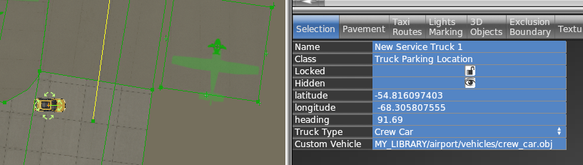
Each “Service vehicle parking location” in WED now has a “Custom vehicle” field where you specify your replacement object. The object itself will be moved around at the same speeds as the selected service truck, for the same purpose (crew car, GPU, fuel truck etc), i.e. the behavior itself is not customizable.
All components of the object (sounds, driver object etc) can be customized by the library author by providing suitably named components to go along with the vehicle object.
How to
Create your vehicle 3D model with animations. The datarefs available for animations and sound are those under sim/graphics/animation/ground_traffic/ (see the Dataref list)
On the SND file (see SND file specification) use start/end conditions according to the datarefs mentioned above. You can also use those datarefs as parameters inside FMOD Studio to modulate the events.
Ensure the events are assigned to the Master Bank androuted to the Exterior Processed > Environment bus.
If you need to apply signal processing (reverb, EQ, etc) to the sounds, don’t apply them to the Environment bus itself because they will be overriden by the corresponding aircraft bus processing. Instead, create a subgroup under Environment to do so.
Expose the object on the scenery or library library.txt (see library.txt specification) so WED can use it, via a EXPORT directive. For example
In WED, place a parking location of the kind of vehicle you want to replace (fuel truck, catering, etc) and under the “Custom vehicle” field, enter the virtual path to your custom vehicle from your library. For example
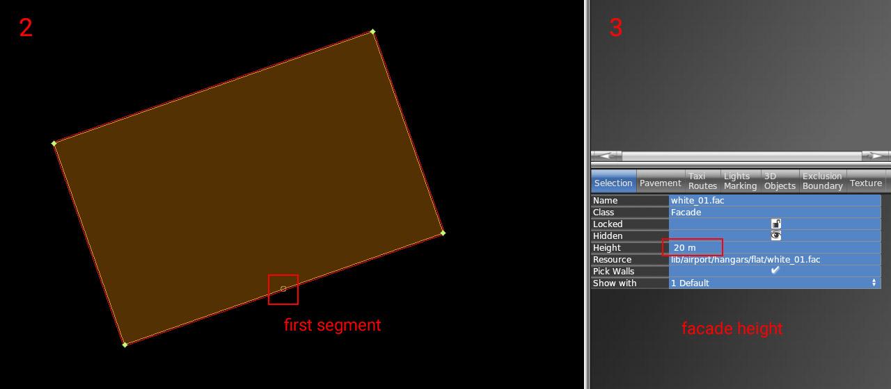
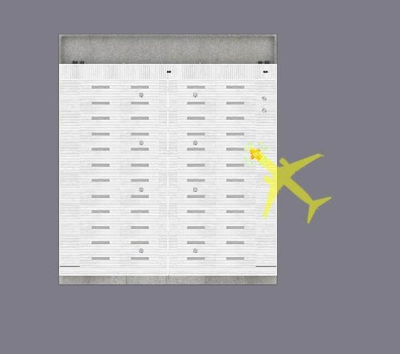
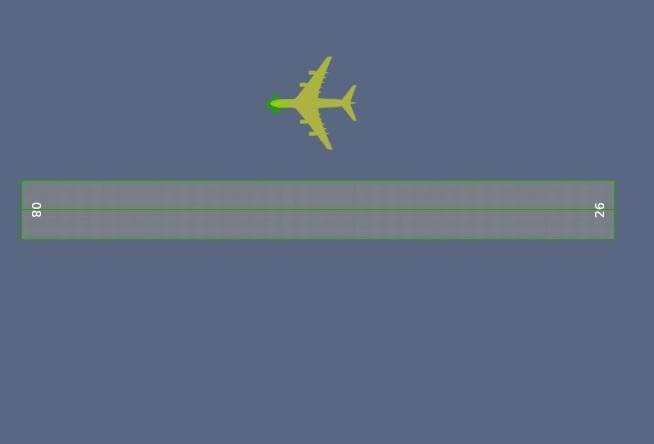
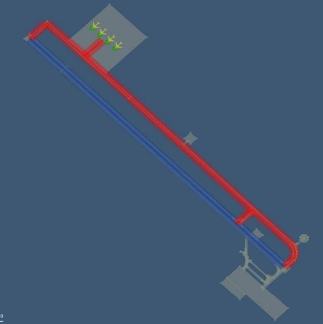
1 – As a first step, you need to put down an exterior facade. You can use any of the facades from lib/airport/hangars/flat/xxx.fac. Make sure the shape is orthogonal (CTRL + Q).
2 – Rotate the polygon (CTRL + R) until you get the first segment (marked with a small circle) to the place where the open doors should be. This is very important for future steps (aligning interior facade and doors)
3 – Set the desired height of the hangar (8, 10, 12, 16, 18, 22, 26, or 30). This is very important because the exact dimensions of openings and related parts may vary based on facade height.
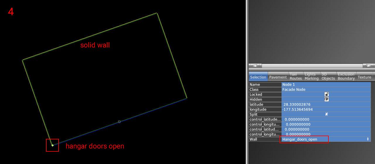
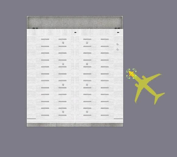
4 – Now set the correct wall types inside vertices. The most important is of course open doors (blue segment). For others, you can use whatever you need (solid walls, windows, etc).
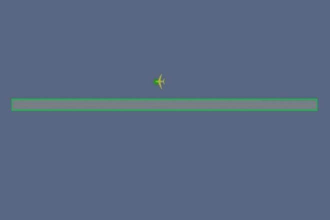
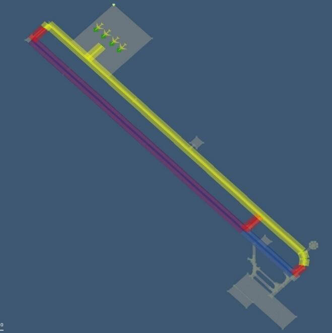
5 – The exterior part is finished. Lock the shape to prevent unwanted edits (turn on the lock icon).
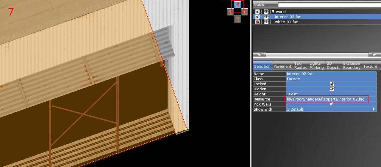
6 – Draw the hangar interior (lib/airport/hangars/flat/parts/interior_xx.fac) following the exact shape of the exterior. Use "snap to vertices" function. You should not break the exterior shape because it is locked.
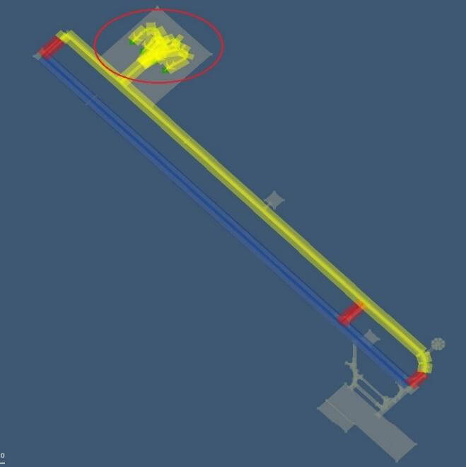
7 – Make sure WED preview is turned on (menu View / Toggle Preview). Zoom to the hangar corner and use an appropriate isometric view.
8 – Set the corresponding height of the interior (7, 9, 11, 15, 17, 21, or 29). Note the height is one meter shorter than the exterior.
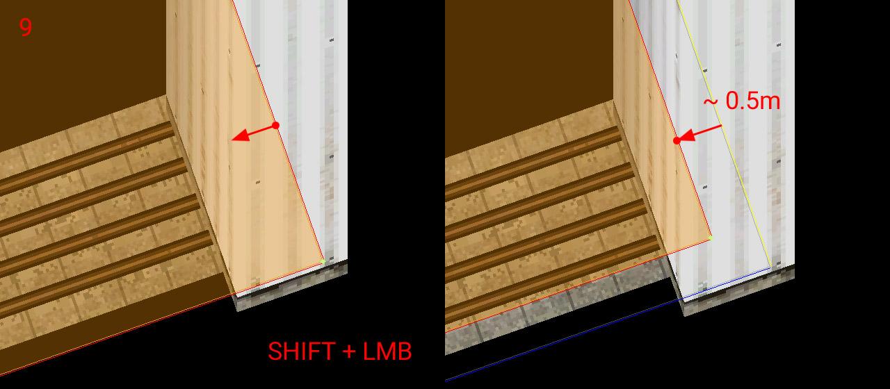
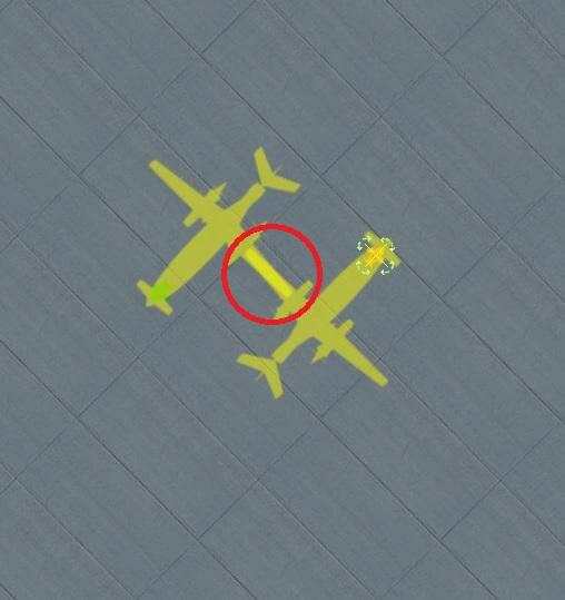
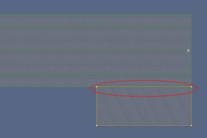
9 – With SHIFT pressed, drag the polygon toward the inside roughly 0.5 meters.
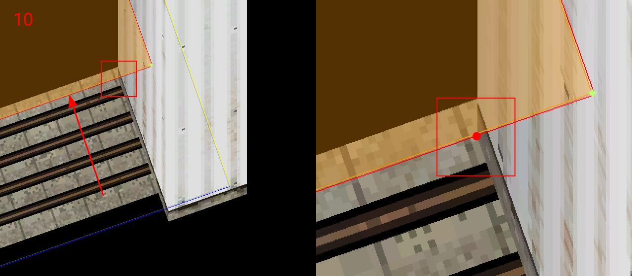
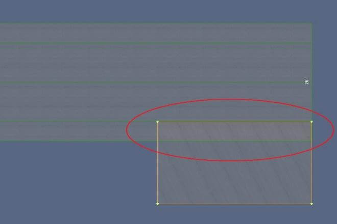
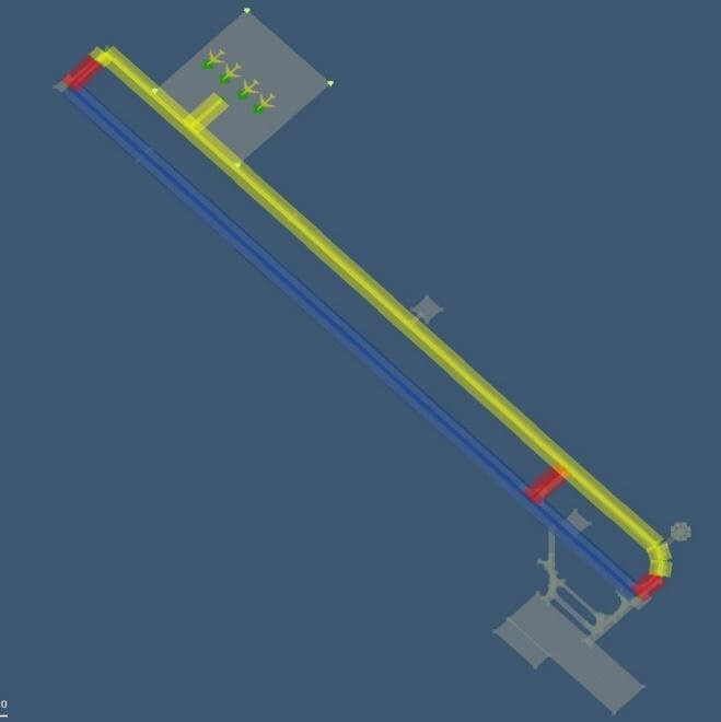
10 – Drag the segment with open doors towards the inside until reaches the end of the opening side. Make sure you're dragging only the single polygon segment (two vertices at a time), not the entire interior polygon.
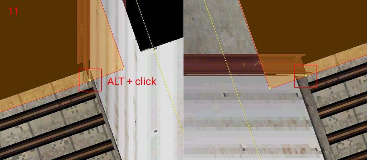
11 – Add a new vertex (using ALT + click) to the intersection of the polygon with the opening. Do the same on the opposite side of the doors (with an appropriate isometric view angle)
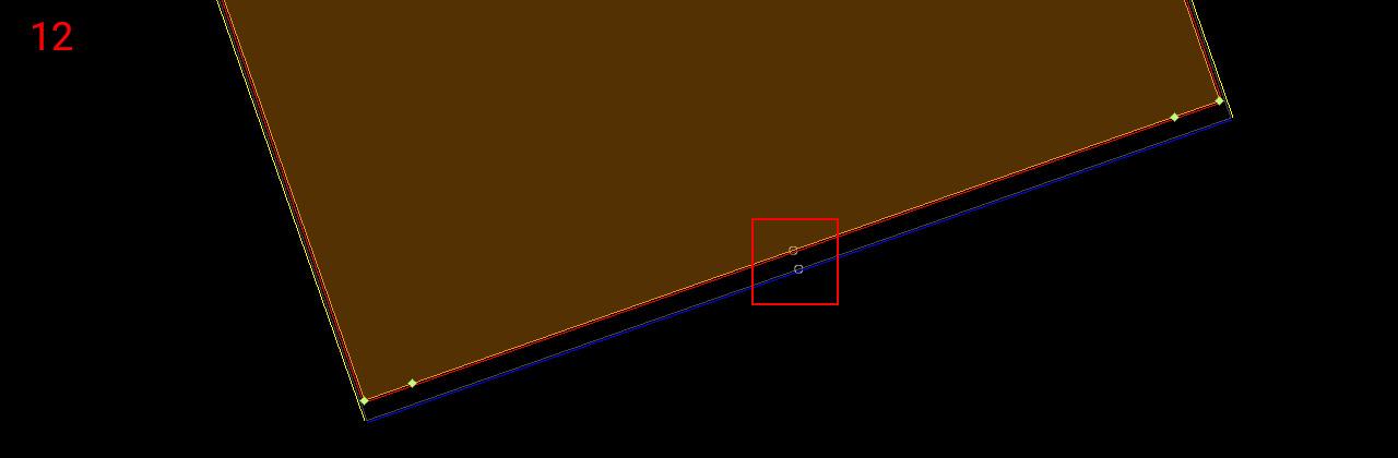
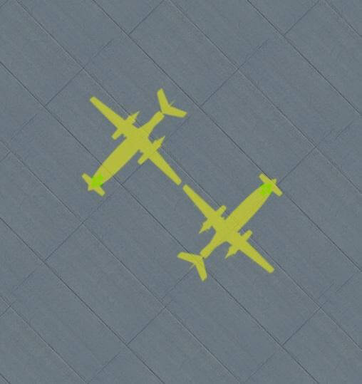
12 – Now rotate polygon segments (Ctrl + R) to get the first segment (white circle) to the corresponding position with the exterior facade polygon. This is very important for the alignment of both facades!
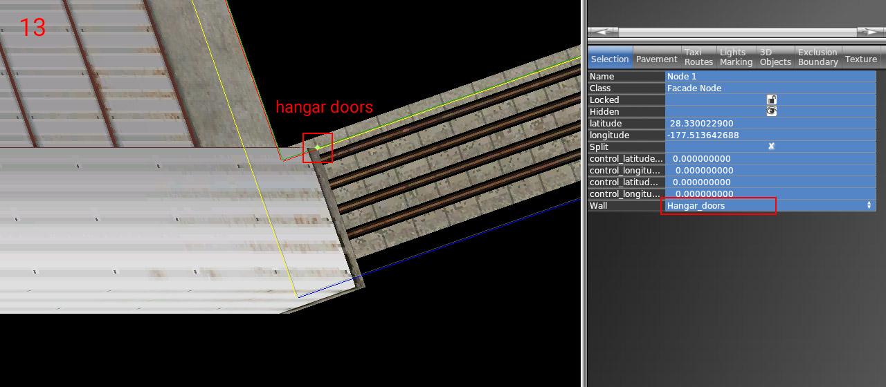
13 – Set the proper wall type to the opening (and other walls eventually). The Interior is done – you can lock the shape.
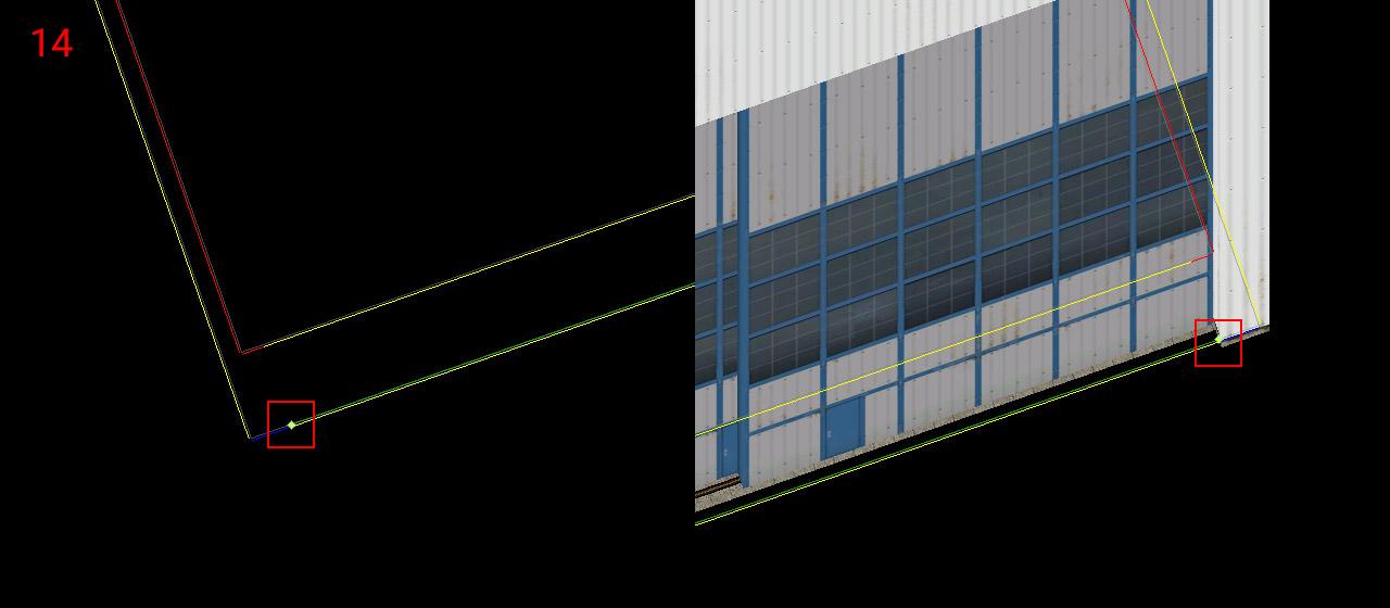
14 – Choose the door facade you want (lib/airport/hangars/flat/parts/hangar_door_xx.fac) and draw a single-segment polygon. Points should be placed exactly on the border of the exterior facade polygon (blue segment). Use the isometric preview to fit both endpoints.
15 – Set the corresponding height of the doors (matching hangar height levels – 8, 10, 12, 16, 18, 22, 26, or 30) and set the wall type to "Hangar_doors_open". You are done!
NOTE: All standalone door facades also have a wall with closed doors (Hangar_doors). This makes no sense in combination with the interior of course. But you can use it for making any combination of the exterior facade design and doors. In that case, you don't need to worry about the interior facade but everything else above is still true.
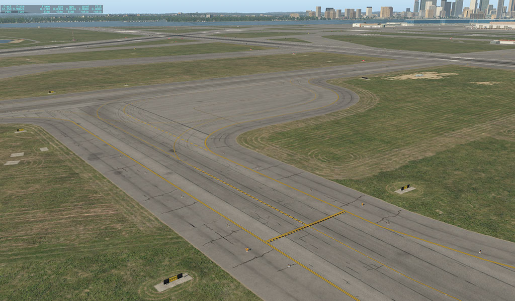
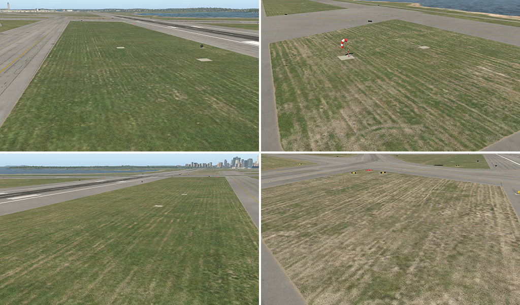
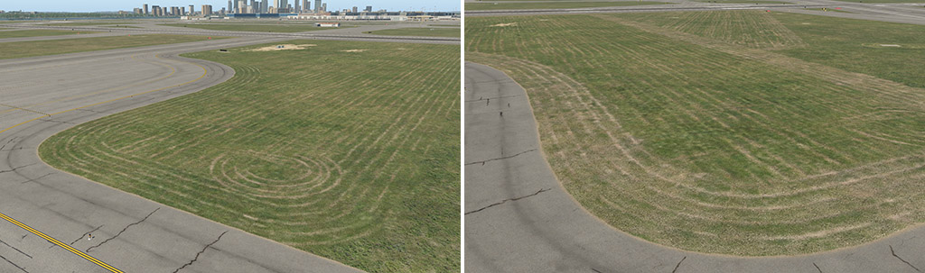
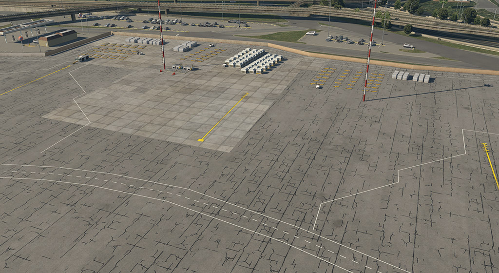
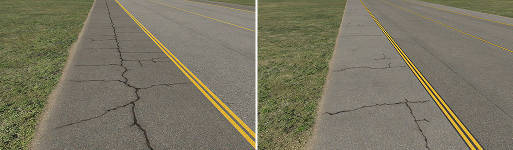
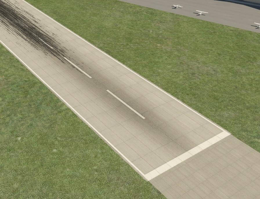
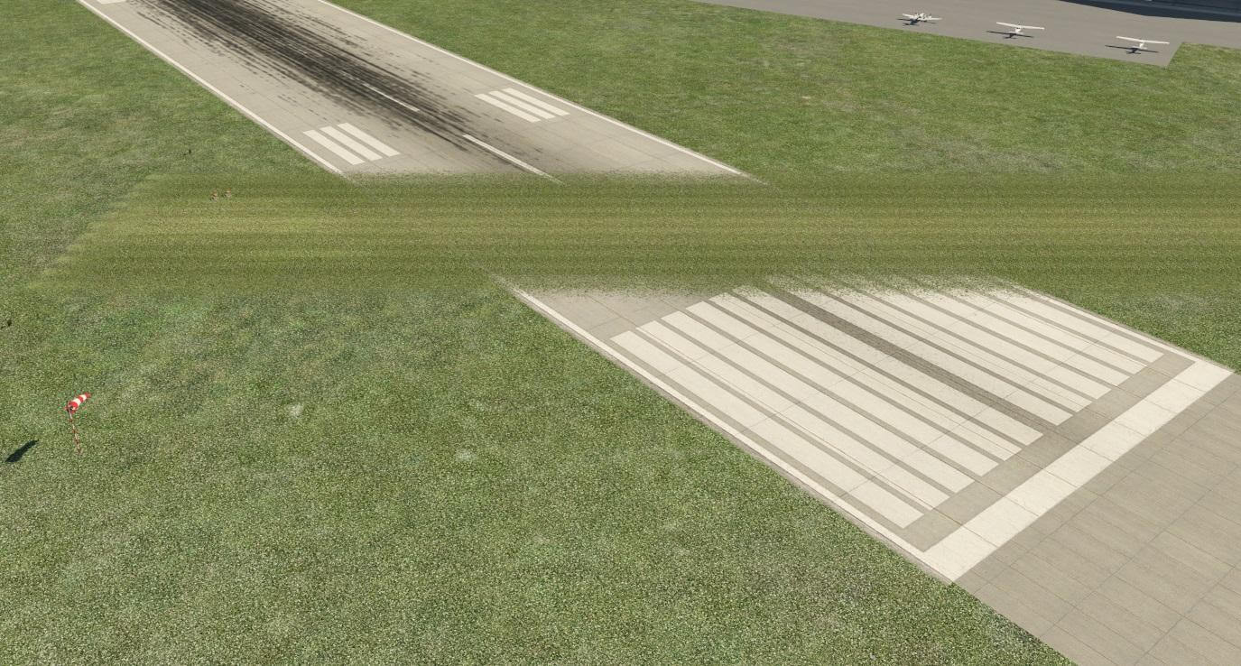
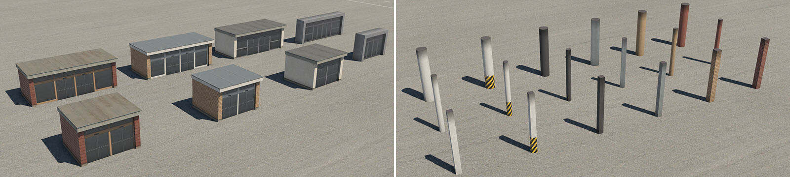
X-Plane 12 has a new set of textures and other art assets. The main idea behind this pack is the general improvement of airports – particularly the depiction of the ground surface. All features in this pack comprise POL, LIN, or simple OBJ assets, and all of them are “ground” oriented. Here is an example of what can be achieved:
The assets in this pack are divided into four categories:
lib/airport/ground/pavement
lib/airport/ground/pavement_FX
lib/airport/ground/terrain
lib/airport/ground/terrain_FX
We can understand these four categories as different groups of layers in the following order:
4 – pavement FX effects placed on, or snapped to paved surfaces (cracks, dirt, grunge, drains, etc.)
3 – pavement main hard surfaces (asphalt, concrete)
2 – terrain FX effects placed on, or snapped to natural surfaces (paths, grass patches, lawn tracks, etc.)
1 – terrain natural terrain (grass, desert, etc.)
A higher value means a higher priority of visibility. In other words, terrain FX won’t be visible through the pavement but the pavement FX over the grass will be shown. That means you can paint a dirt path across the border of asphalt, but you shouldn’t paint asphalt cracks across the border of grass.
1 – Terrain
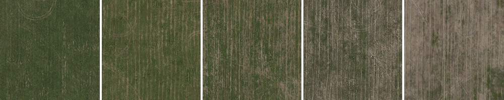
We have brand new textures and shaders for all basic airport terrains. The grass is completely new, the desert is new, and so on.
In addition, we have unique grass textures with lawn-mower tracks. This is a typical detail that can make the terrain look more realistic. These textures are directional so for better plausibility, it is very important to set the proper direction in WED polygons.
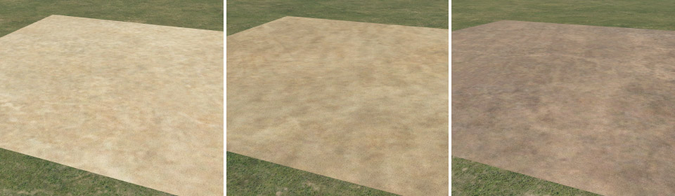
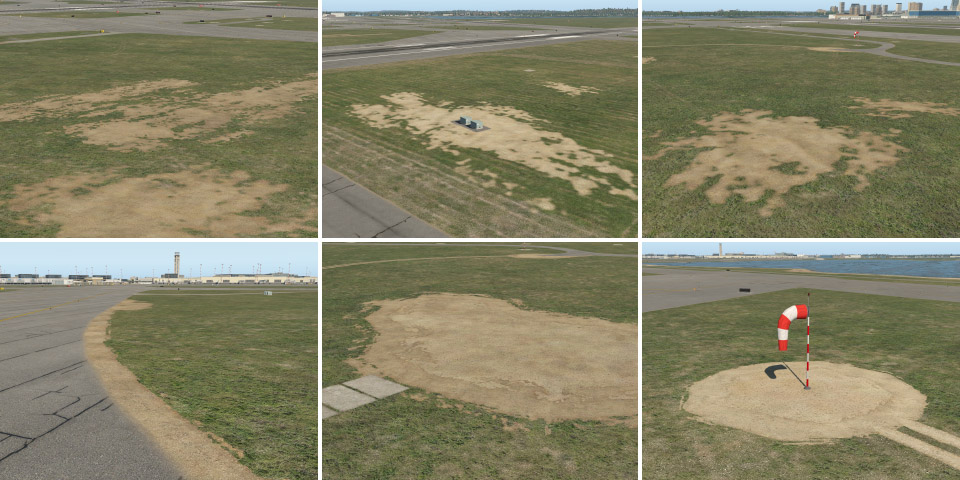
Next, we have textures for sand and soil. It can be useful for various patches in the grass.
2 – Terrain_FX
This is a group of effects that can be placed on top of natural terrain.
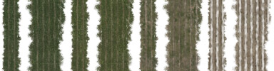
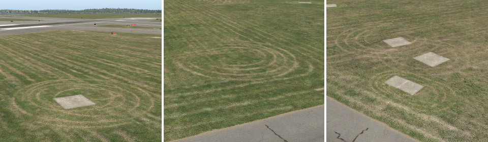
lawn_tracks
The lawn-mower tracks effect comes in different forms. POL (polygon) files have a similar visual effect to those above. This time, however, they are transparent and contain only the lawnmower tracks themselves. It can be placed on top of any type of underlying terrain (which can be handy for locations where nice green grass is not desired).
LIN (line or stripe) files are useful as a natural border between grass with a lawn-mower effect and surrounding areas. Typically these can form the natural shape of grass islands in between taxiways. We have various strips with corresponding colors of grass.
Typical use:
OBJ (object) files are mostly spots with a couple of tracks in circular form. These can be placed typically in corners, or under various things in the middle of the grass (like taxi signs).
patches
Patches are available as single OBJ (various sizes and shapes) and as LIN (various widths). We also have all corresponding colors for basic terrain polygons – grass, dark grass, dry grass, light and dark sand, and soil. They’re useful for modeling various imperfections in basic terrain, spots, broken lawns, and so on. Also, these can be used along the edge of a taxiway, as an extension of the natural edges (see below).
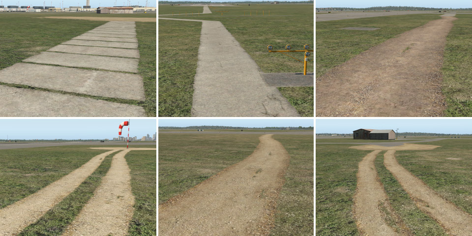
paths
Path LIN are available in various widths and materials (concrete, sand, and soil).
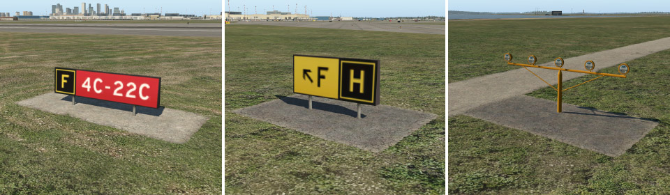
taxi_sign_base
These are paved bases for taxiway signs. Single OBJ are available in various sizes, and two colors (light and dark). If you can’t find the desired size for a certain situation, you can also use the LIN variant. These OBJ have an exception to the layer system described above. They render above the pavement so you can use them also on top of taxiways.
3 – Pavement
In X-Plane 12 we also have a brand new shader designed particularly for hard airport surfaces. Generally speaking, it can make better-looking asphalt and concrete, with less obvious texture repetitions over large areas (almost invisible repetitions).
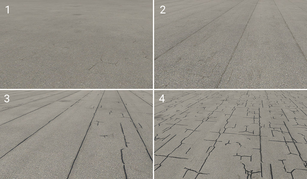
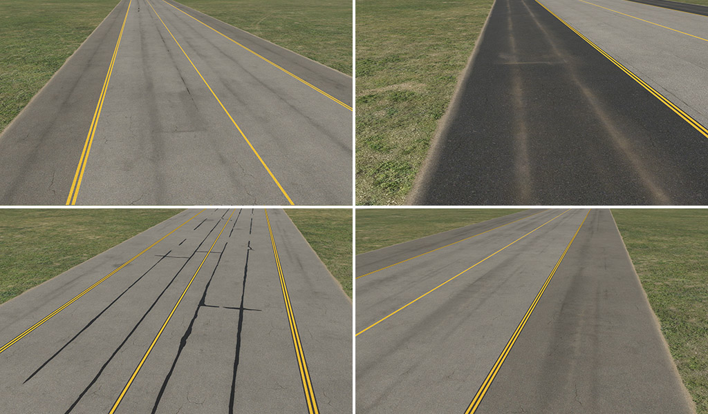
asphalt_
Asphalt surfaces are available in five basic colors (light to dark).
Each color variant is available with four different effects:
1 – plain: this variant is omnidirectional. It is useful for specific situations (typically taxiway shoulders) in conjunction with various effects (see below).
2 – strips: this is probably the most common variant with typically visible strips.
3 – worn: same as (2), but a bit worn. Gaps between strips are sometimes cracked or patched.
4 – patched: highly worn, irregular, and more visible cracks.
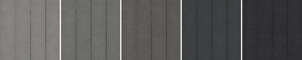
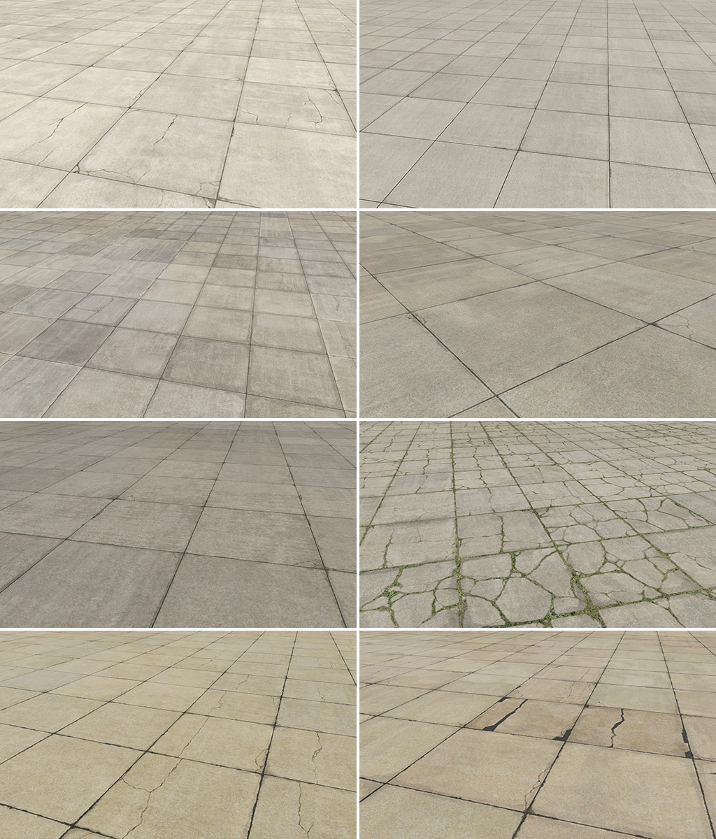
concrete_
Concrete doesn’t have a unified system like asphalt. We have three main colors (gray, light gray, and dark gray) but with slightly different effects for each of them. In addition, we also have the fourth color group which is tinted (red or yellowish). Here are some samples of the variants:
4 – Pavement_FX
This is a group of effects that can be placed on top of hard surfaces.
edges
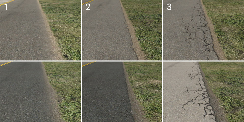
Probably the most important asset. Edges are dividers of pavement and natural surrounding terrain. They are available in two colors (light and dark) and have three variants:
1 – soft: basic edge with a slight plastic effect. Suitable for most common situations, particularly for grass.
2 – elevated: pavement surface looks slightly elevated, and the edge is a little worn.
3 – cracked: a lot more cracked and worn.
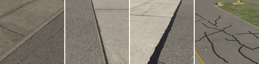
gaps
These are dividers of adjacent asphalt or concrete surfaces. A wide patch line can be used for manually painted large-scale cracks, however we recommend you do not repeat this small texture to cover large areas.
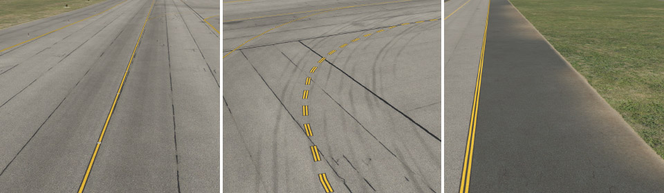
taxiway
Here we have four different types of taxiway structures. Imagine transparent strips, with the very subtle effect of dirt on asphalt. These were designed to be used in conjunction with the plain variant of asphalt. These are useful for curved segments of taxiways and particularly shoulders, and are available in different widths, which should roughly match the usual sizes of shoulders.
taxiway_cracks
Another kind of effect that is useful, especially for shoulders. Also available in different widths.
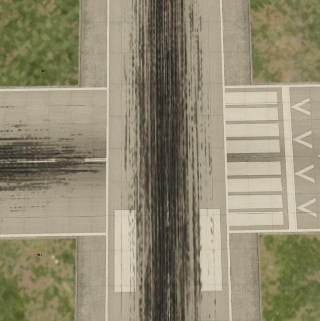
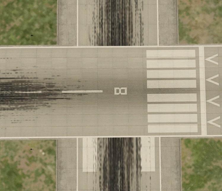
taxiway_dirt
In this group, you can find subtle dirt effects. Some are designed for placement along the centerline, others are for the edge of the taxiway.
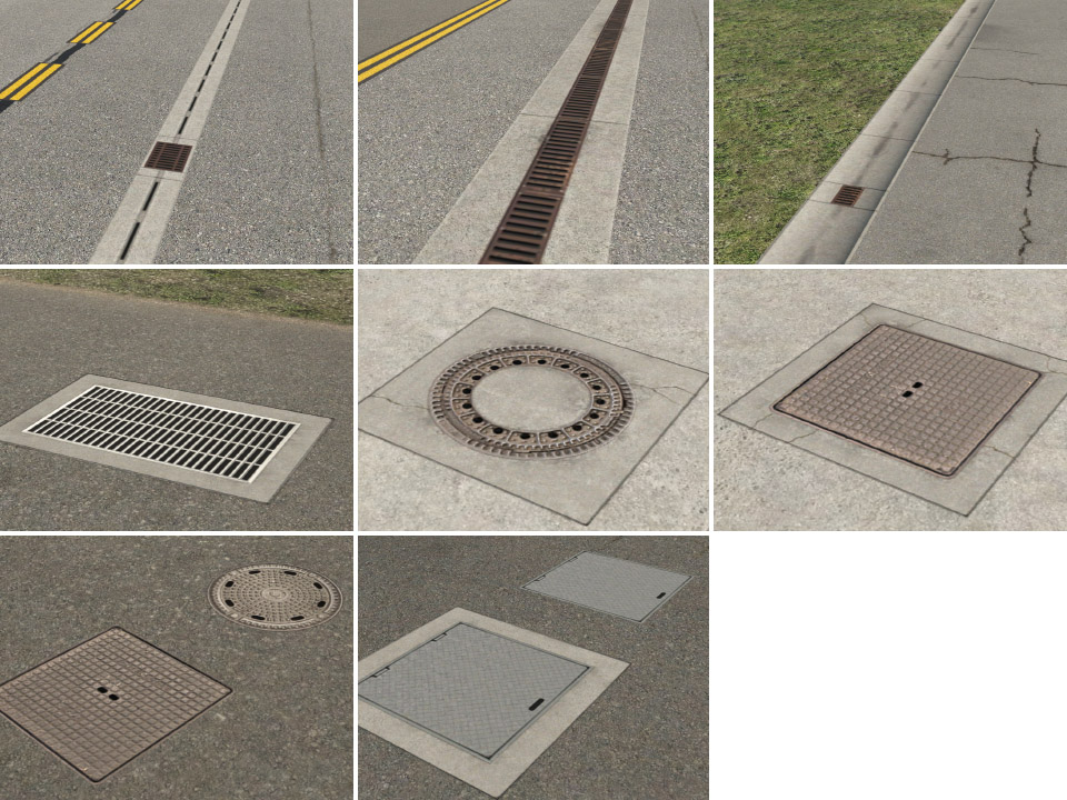
drains
Various drains and manhole cover lids.
General hint: most LIN effects have end caps. That means the line needs some minimum length. Any time you see an artifact (black rectangles), it is probably due to insufficient length of the line.
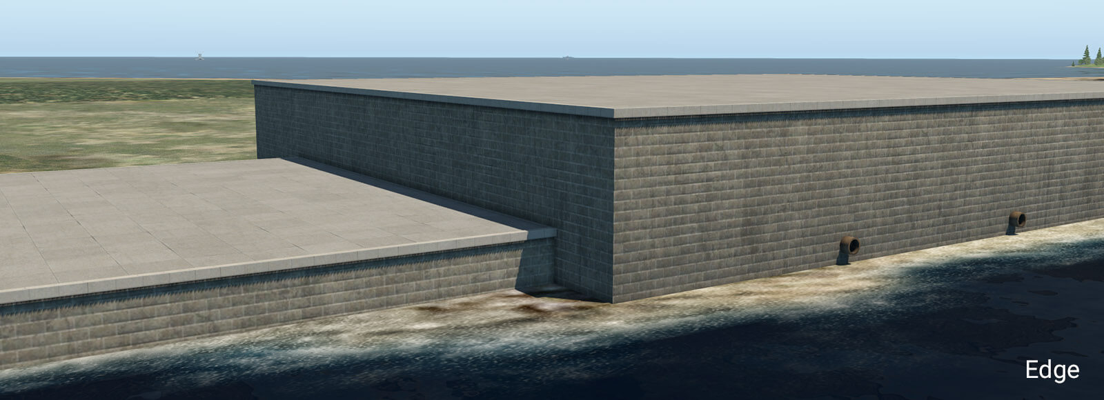
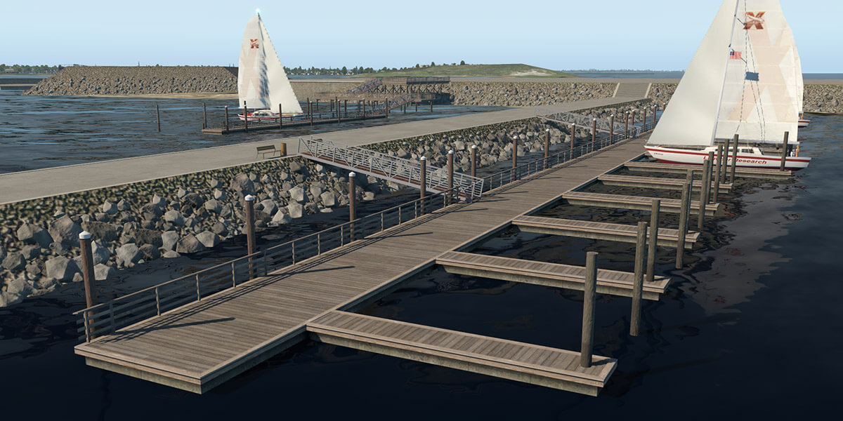
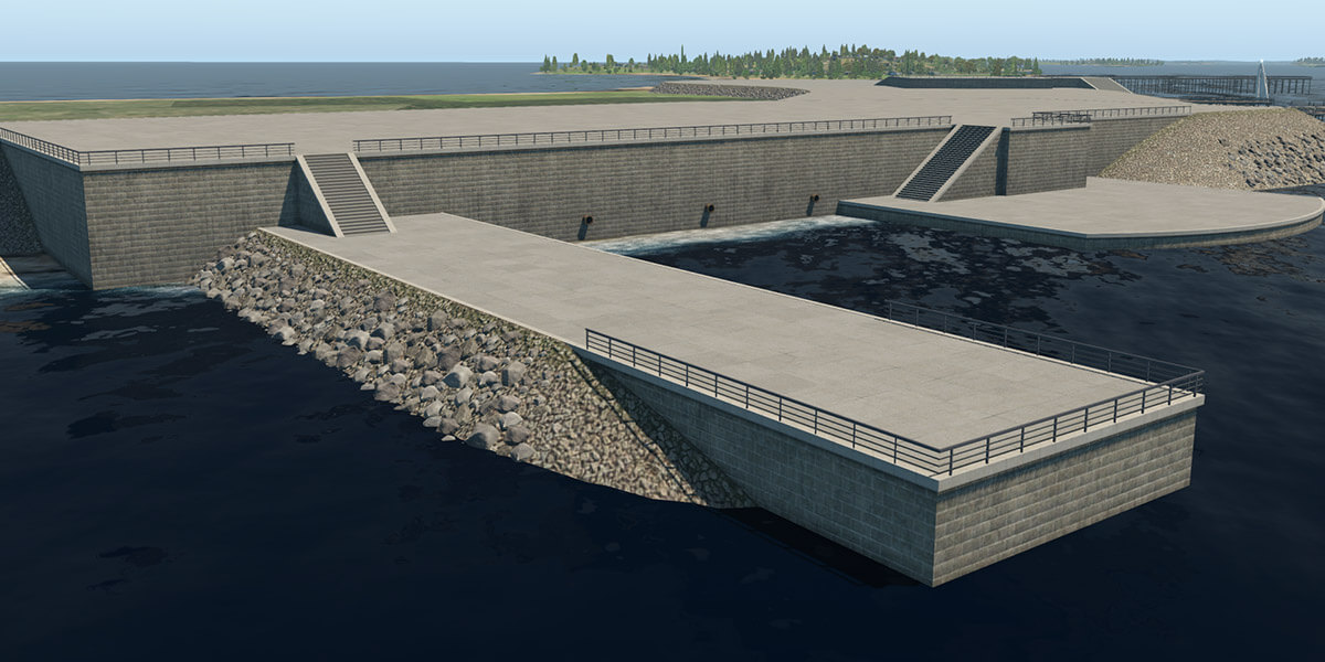
X-Plane 11.30 introduces new facades and objects for the creation of embankments, sea-walls, piers, and docks. These can be found in the WED library hierarchy at: “lib/constructions/piers“.
Key components are special facades with various wall types for specific usage (similar to the ‘Terminal kit’ introduced in an earlier release). This facade is used in the main for the creation of ship ports, quays, river banks and sea-walls.
embankment_01.fac
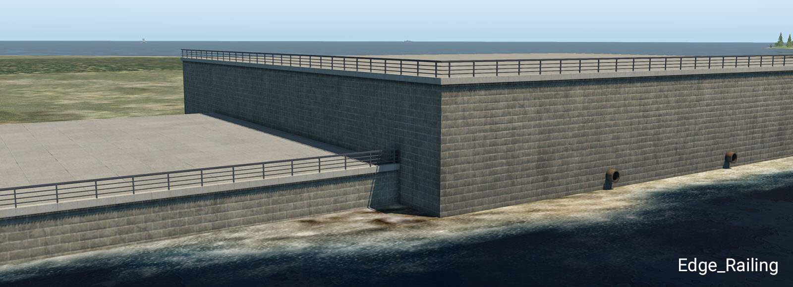
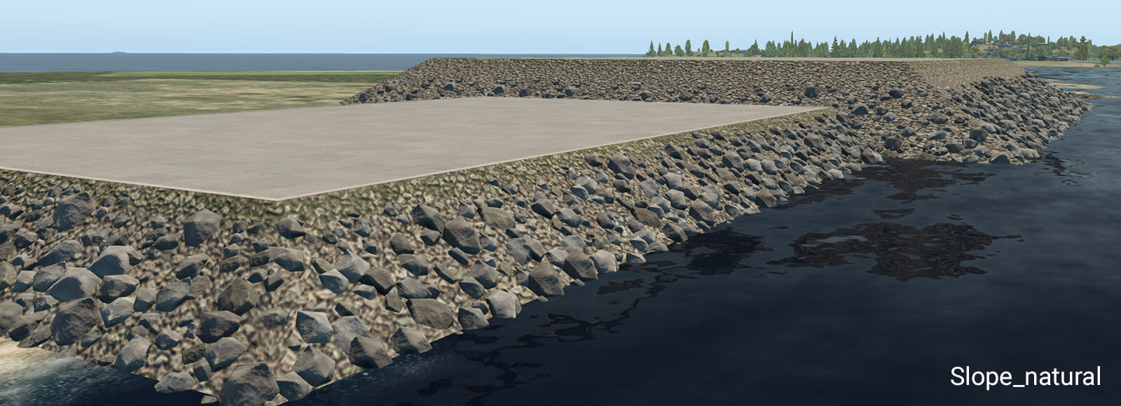
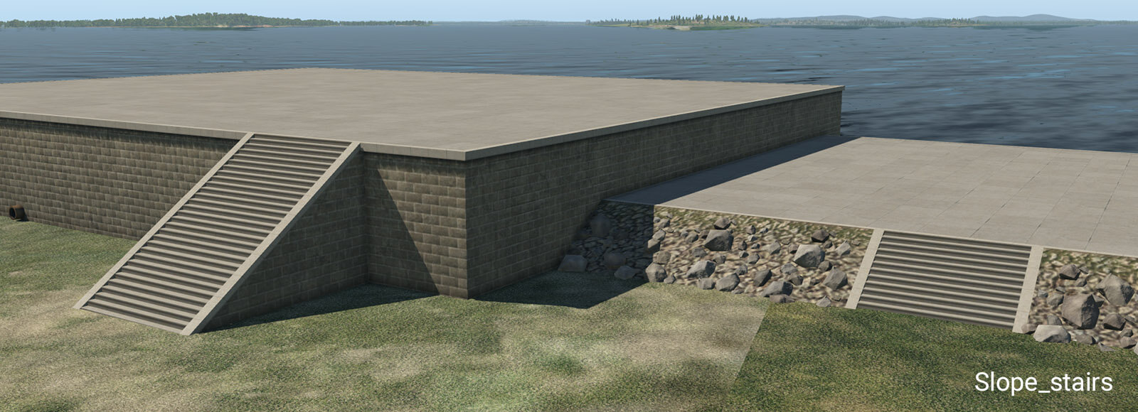
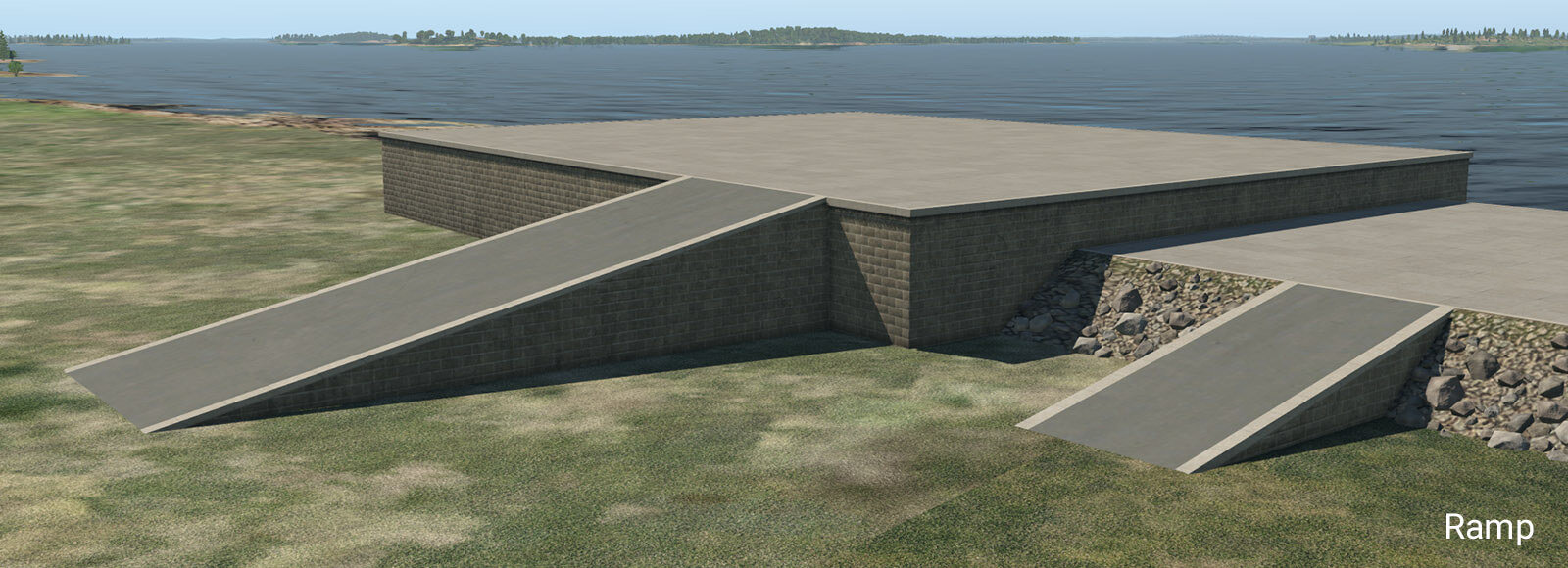
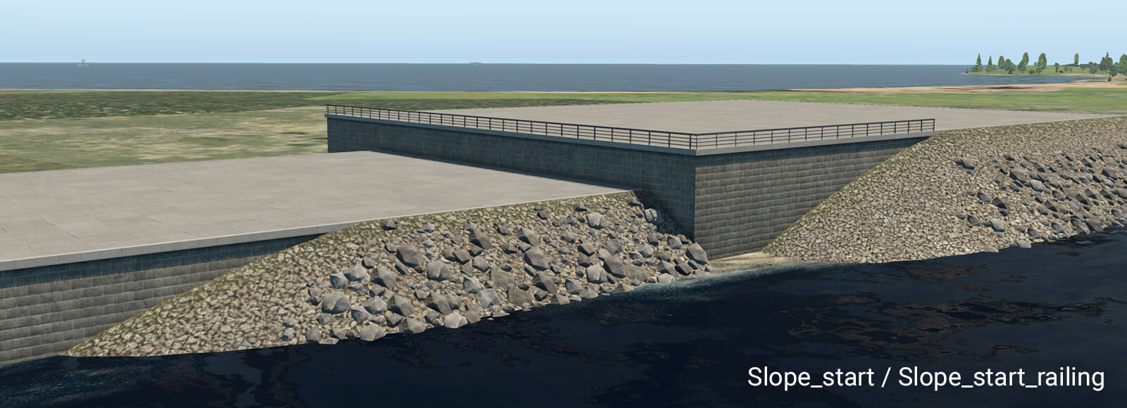
This facade can form a typical stone embankment with vertical and sloped walls. It is designed for height ranges between one and ten meters, with a one-meter step. This facade must be placed as a closed polygon, with manually selected walls. Due to the nature of the facade system, there are some design limitations. The basic vertical wall works without any specific limitations. However, sloped walls (like natural slope, stairs or ramp) don’t work very well in conjunction with sharp angles at corners. When the corner angle is 90 degrees and more, there is an obvious distortion in UV texture mapping. This may look silly, especially with the greater height so try to avoid very sharp corner angles when using these walls. For the same reason, it is not recommended to switch between vertical and sloped walls at corners. This works best with straight polygon segments.
Stairs have exactly the same angle as the natural slope so they can be seamlessly placed in between sloped walls.
The ramp is designed for straight segments. Do not use it at sharp corners, because it has very obvious UV texture deformations due to its shape.
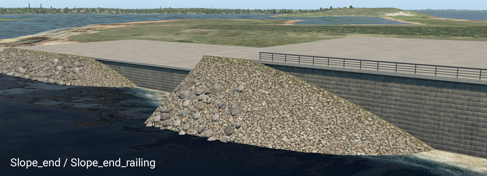
These pairs of transition segments are useful when you need a smooth transition between the vertical wall and natural slope. They work best in straight segments also. Note they require some length to be shown properly. A safe length is about 32 meters. However, you can make the transition segment much longer. If you do so, “Slope_start” will appear at the very beginning of that segment, and “Slope_end” will appear at the very end.
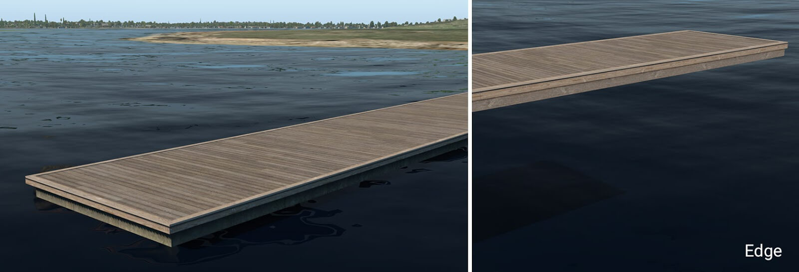
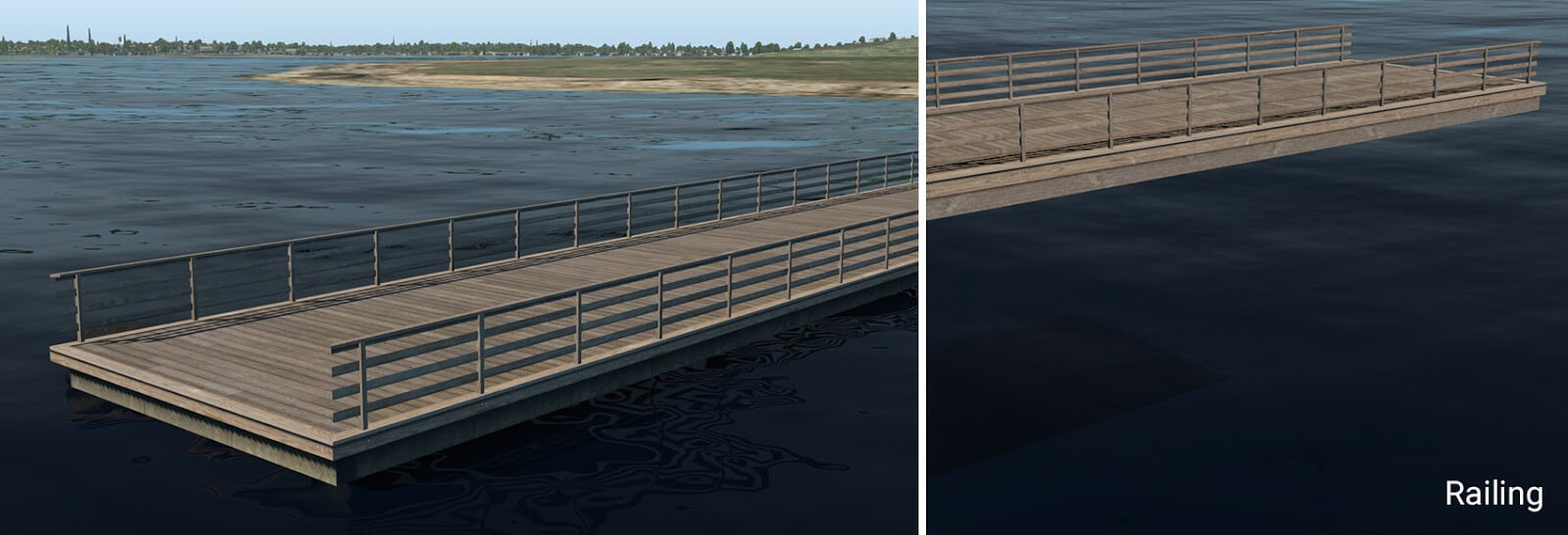
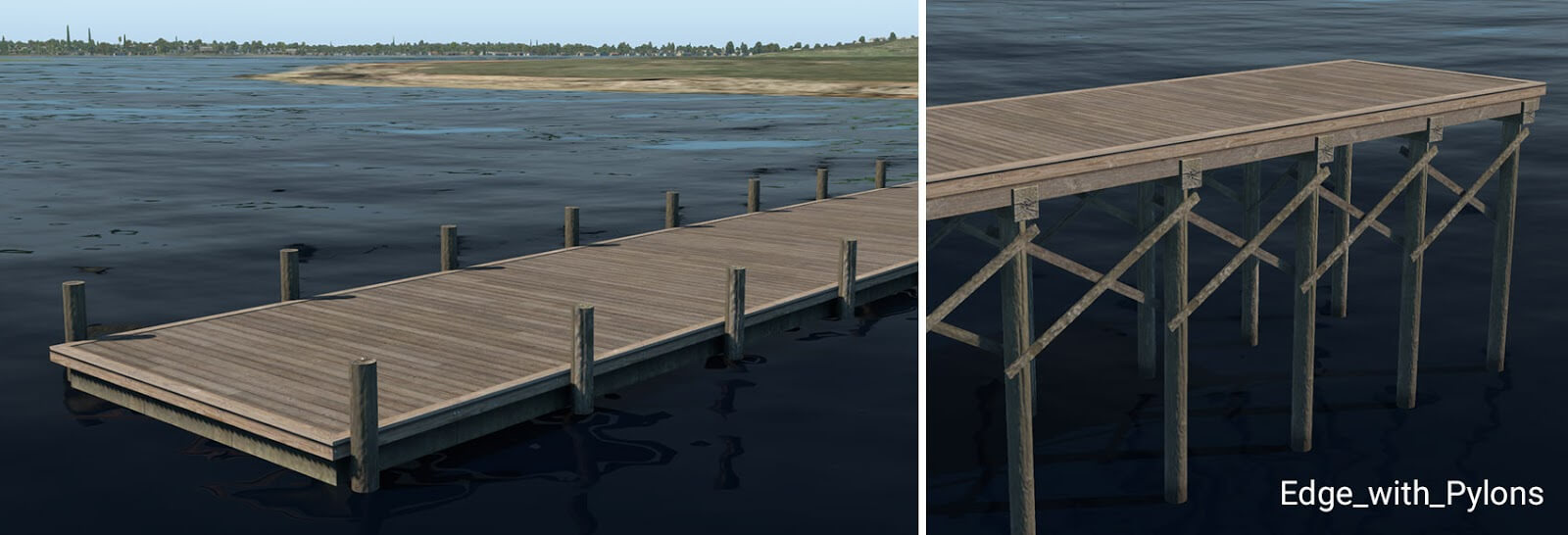
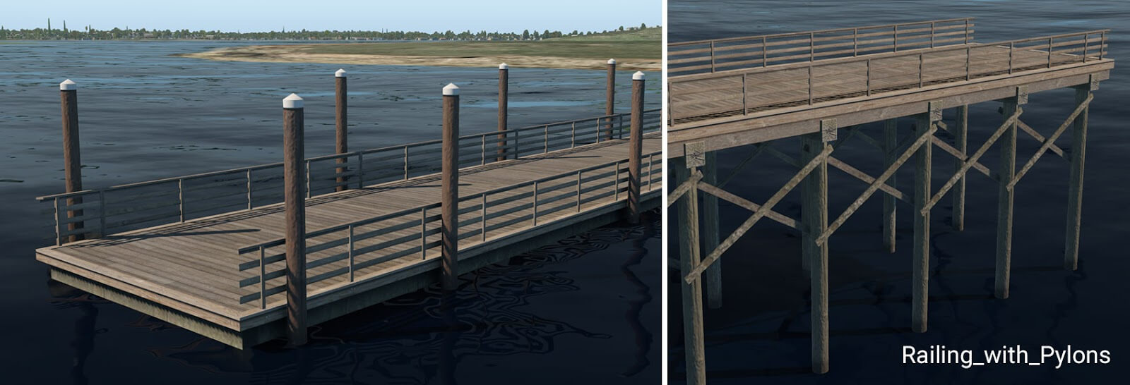
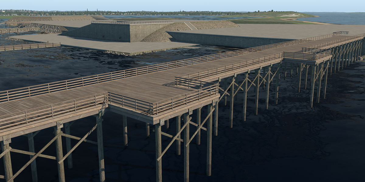
pier_wooden_01.fac
This facade is used in the main for the creation of typical wooden piers or docks. It works for the same height ranges (1 to 10) plus an additional 0.6 meters. This is because 60 cm is a typical height for small floating piers. The two lowest height levels (0.6 and 1 meter) look like a floating pier and the rest form a pier on pylons.
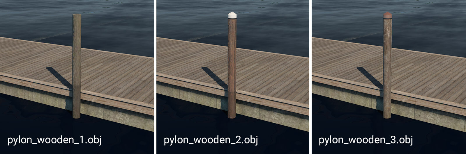
pylon_wooden_X.obj
These pylons can be placed manually. They are useful in combination with floating wooden piers. For more convenient placement, they are also available as strings: “pylons_row_wooden_X.str”.
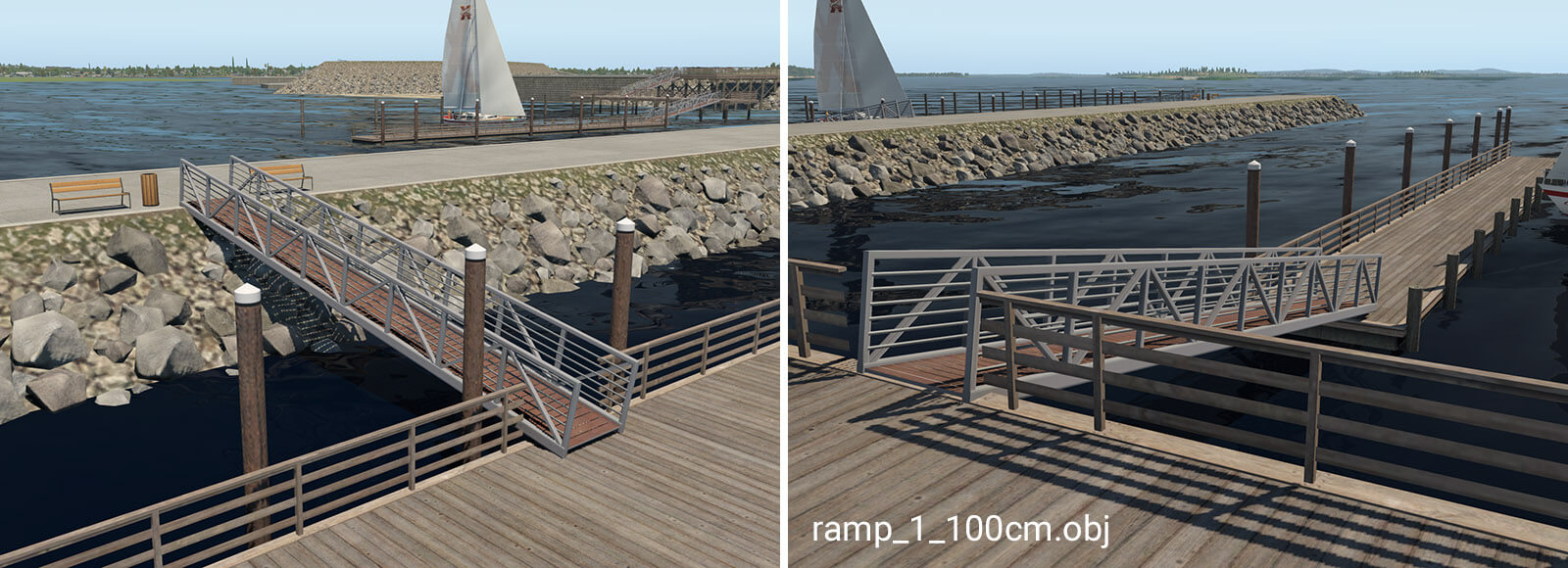
ramp_1_100cm.obj
The ramp object is available in seven different variants. It is designed for connections between levels with differing heights. The numbers in the name mean the total height of the ramp (e.g. ramp_1_240cm is 2.4 meters high). This object is available with heights of 140, 240 and 340 which is necessary in conjunction with the special 60cm pier. For proper placement of the ramp above the pier, artists must use the ‘Set MSL’ feature in WED, with the appropriate altitude above sea level.
You can access the global preferences from under the File (Windows) or WED (Mac) menu option. Here you can change between meters or feet, and how coordinates are displayed. (Note that Moderator mode is only useful if you are a Gateway Moderator so always leave this turned off.)
Preset METAR ICAO
WED will automatically create meaningful wind/time rules names based on the airport METAR ICAO and time a relevant properties for any Wind, Time or Runway Use rules is changed. This keeps the flow rules more legible, the flow rule name itself has no relevance outside WED.
Updating old data
Smart runway rename
When a runway is renamed due to magnetic variation changes, not only the runway name, but also all ATC taxi routes, flows and taxi signs need to be fixed to match the changed designation. WED will detect such edits of a runway “name” property, find all these references, update them and let you know. This greatly helps when the runway validation tells you it’s missing some runway at that airport – which usually means some existing runway was recently renamed due to magnetic variation changes.
After changes of the runway name property a popup windows will announce the number of changed ATC taxi routes/ Flow rules / 3D Taxi signs to confirm the smart rename action.
To change a runway name without invoking the smart renamer, first change the runway name to some illegal name, then in a second operation to the desired new runway name.
Align Airports
Select an airport, then go to Airport menu > Align Airports. This function can be used to mass-move the currently selected airports to bring runways into CIFP compliance. It will also select only unchanged airports after the operation completed, to facilitate deletion and re-submission of only the changed airports to the gateway.
Explode special AGPs
Edit > Explode Special AGPs takes certain scenery .agp group objects (such as lib/airport/Ramp_Equipment/ 250cm_Jetway_Group.agp) and replaces them with the individual .obj components included in the group. You can further modify that “group” by moving or deleting the individual objects that make up the group.
This only works for a few predetermined public .agp groups, mostly these jetway groups. It also requires that all items in that .agp group are available as individual .obj items for placement in WED.
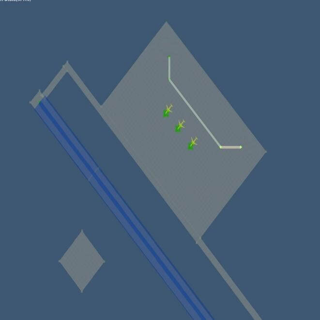
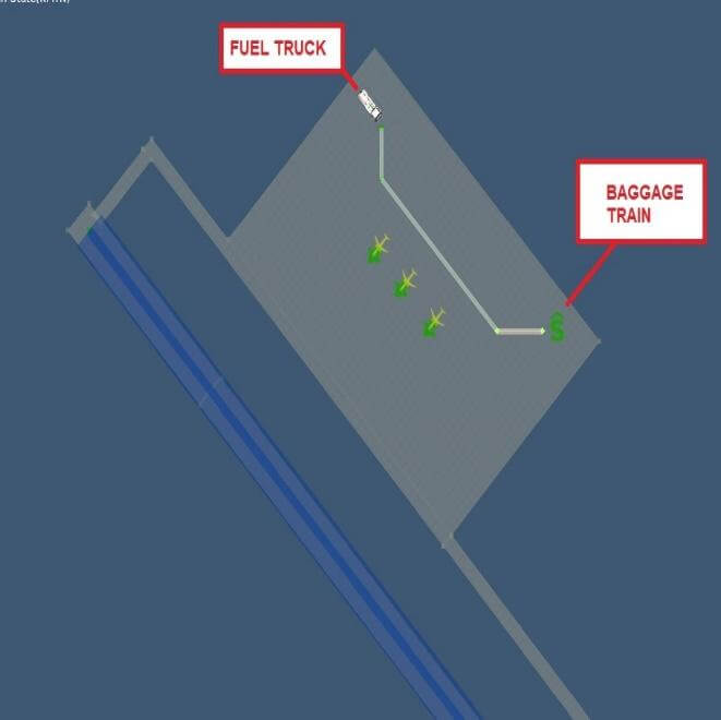
Replace Vehicle Objects
Edit > Replace Vehicle Objects takes X-Plane 10 sceneries and replaces all .objs depicting ground service vehicles found on all airports in the scenery and replaces each one with the equivalent X-Plane 11 Ground Service Vehicle start definitions. E.g. it turns the static Belt_Loader.obj into the X-Plane 11 service vehicle that actually moves around.
This function can be used in conjunction with the previous one to first break up the jetway groups into the individual .objs (Belt_Loaders, Baggage Trains, GPUs etc) and then convert those pieces into Ground Service Vehicle starts if applicable.
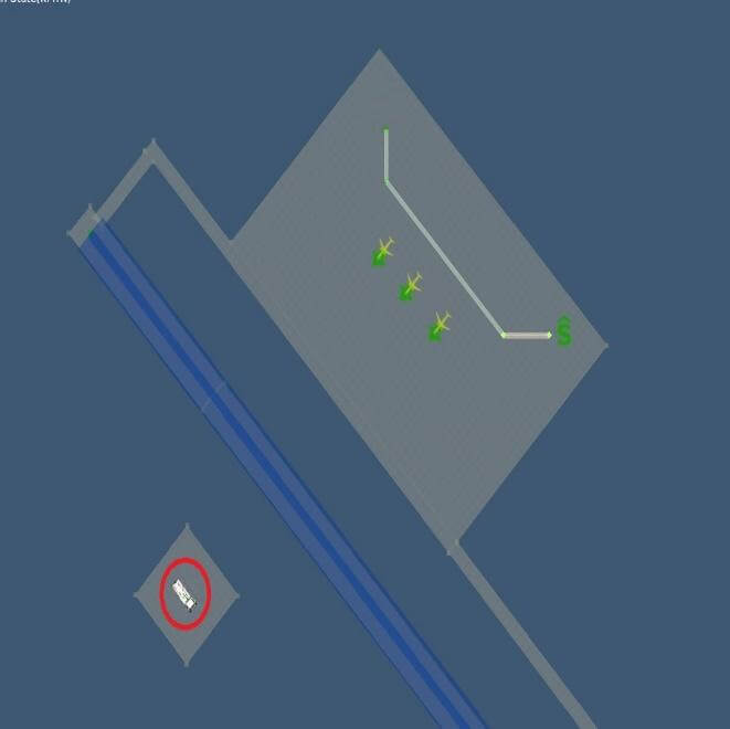
This feature sounds nice at first, but the Ground Service Vehicle starts really need to be placed strategically near a Ground Vehicle Route to really “work” right. But it’s a quick way to create lots of strangely behaving ground vehicle traffic.
Upgrade Ramps
Airport > Upgrade Ramps takes pre-X-Plane 10.50 sceneries with ramp starts and adds useful defaults for the X-Plane 10.50 properties that were added to those starts. Also deletes certain .obj known to depict static aircraft in the vicinity of these ramp starts, so as to eliminate conflicts with the X-Plane “Draw Parked Aircraft” function.
E.g. all ramp starts of type = Gate start get Operation type = Airline added, all type = Tiedown turn into either Airline or General Aviation operations, depending on the ramp start size parameters.
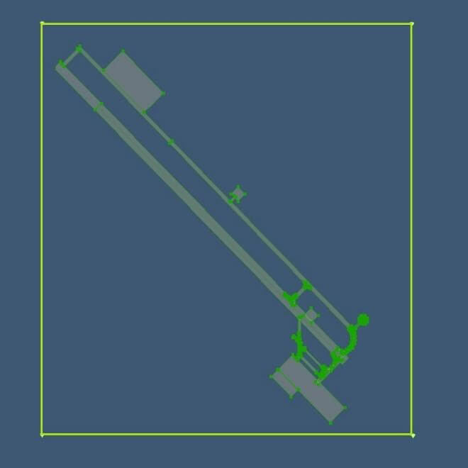
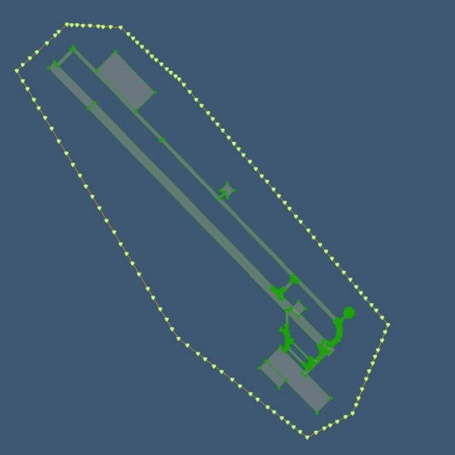
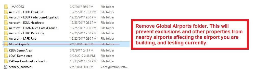
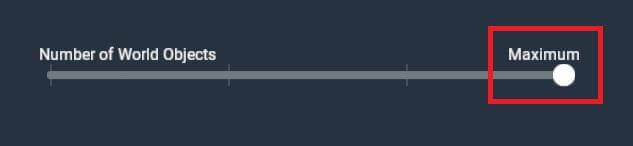
Scenery artists tend to draw wide airport boundaries to “defend” their airport against overlapping objects from all kinds of default and addon sceneries. But in the long term, this does more harm than good. While there is no firm rule on what is “too close” or “too wide” for airport boundaries, airport boundaries can greatly affect scenery results after an X-Plane update or version change.
Scenery is typically only recut between versions, and the airport boundary is what is used to flatten and shape the area around an airport.
Having a tight boundary with tens or hundreds of nodes can greatly affect the detail of the surroudning base mesh. The terrain mesh uses terrain triangles to follow the airport boundary exactly, as it is not allowed to simplify (aka cut corners) here. If there are a lot of nodes in the boundary, the terrain will require a lot of triangles which reduces the detail available for the rest of the 1×1 degree tile area.
The airport boundary is NOT a tool to trace political/legal boundaries or to determine where the airport grass should be visible or not. It is to define the area where your particular layout needs to have (somewhat) flat and level ground and to be free of 3D autogen/addon scenery items. (Note that roads are not 3D items, so these are not affected by airport boundaries.)
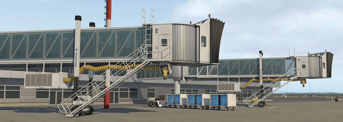
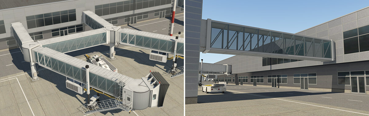
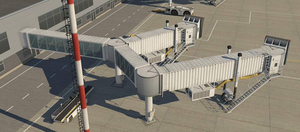
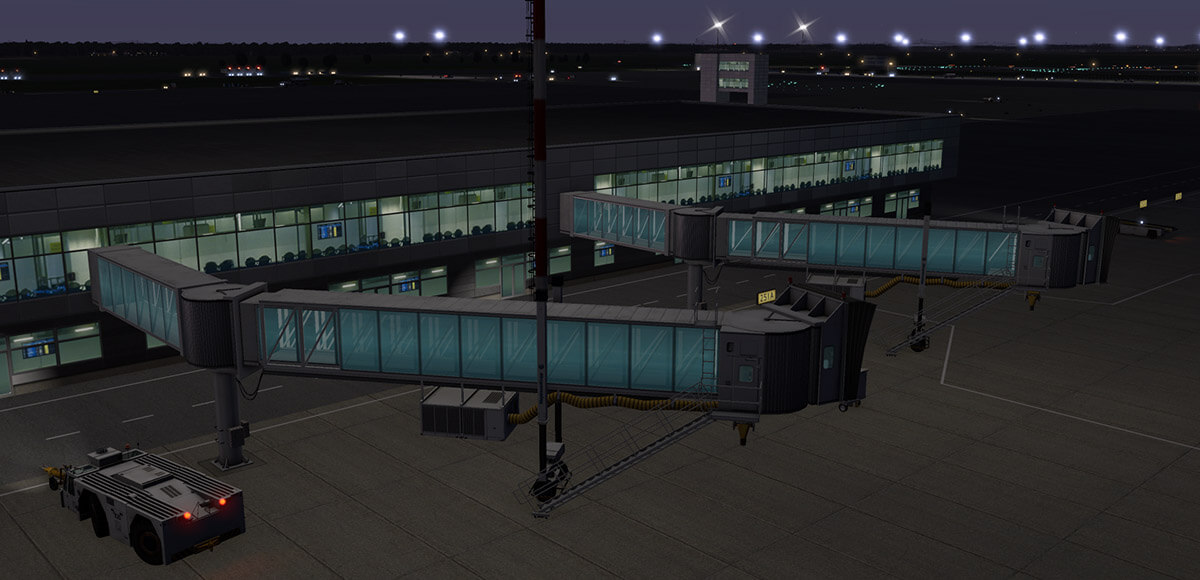
X-Plane 11.20 introduces a new object-type for the construction of jetways. Technically this is a facade, and therefore in WED appears as an unclosed chain of segments. This approach allows the artist to customize jetway shape and position for almost any real world situation. Moreover, it is very easy to use, and you can build a custom jetway literally with just a few steps.
The jetway system can handle an unlimited number of extension bridges in a single chain, and telescopic bridges in a range of 11 to 40 meters. By design, jetways are always horizontal.
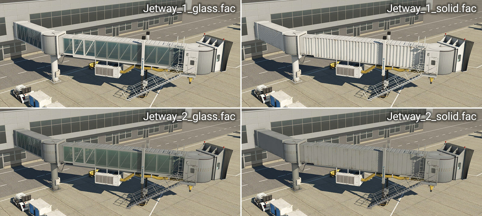
Jetway objects can be found in the WED library hierarchy at “lib/airport/Ramp_Equipment/Jetways“. Currently, four jetway-types are available:
Basic steps for the creation of jetways
1 – Pick the jetway facade and place the chain of nodes
2 – Set the “Pick Walls” checkbox
3 – Select the desired vertex (wall-type) for each segment
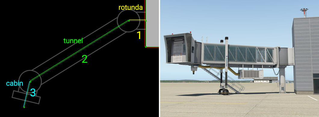
In a typical use case, the artist would place a chain with three segments (four nodes). Order of placement is important – always start at the terminal wall. (Note: Ctrl+Shift+R may be used to reverse the chain-order.) The artist must always set the vertex (wall type) manually. X-Plane can’t guess which segment is a telescopic tunnel and which is an extension or a cabin, for example.
A typical jetway is always made of three parts. The first segment, rotunda, represents the connection between the terminal building and pivot point of the jetway bridge. The second segment represents the main body – a telescopic tunnel. The last segment must be the cabin.
Diagram illustrating the basic concept:
The parts of a jetway in detail
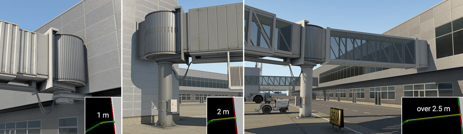
Segment 1 – Rotunda
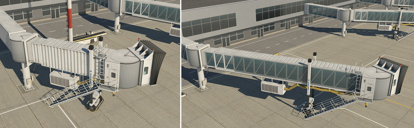
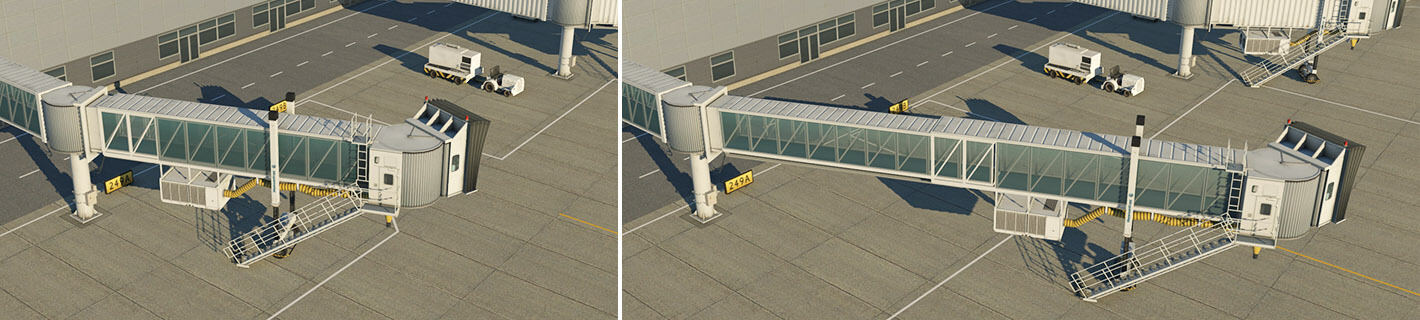
The first segment (Rotunda) may be as long as required. However, the visual representation depends on its length. If it is very short (such as 1 meter), only a rotunda without a column appears on the wall of the terminal. If its length is between 1.5 and 2.5 meters, it shows the usual short neck and rotunda with a column, which is most common in the real world. With a length of more than 2.5 meters, and up to a maximum of 60 meters, it forms an extension bridge, ending with the rotunda and the column.
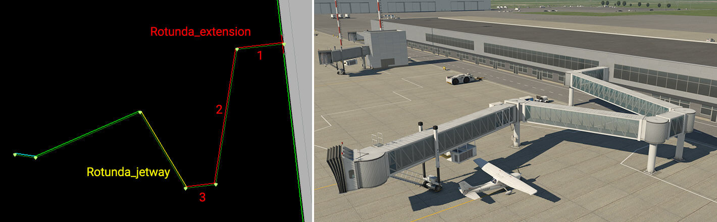
You may place multiple extension bridges in one chain to build very complex structures.
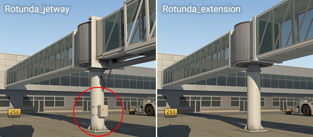
Rotunda segments have two vertex (wall-type) options – “Rotunda_extension” and “Rotunda_jetway“. Both behave exactly the same way, and the difference is merely visual. “Rotunda_jetway” has some electrical installation and is intended for use with telescopic tunnels, while “Rotunda_extension” is intended for additional extension segments.
Segment 2 – Tunnel
This segment must be at least 11 meters long and there are two options here. Artists may select the “Tunnel_parked” vertex (wall type) which is probably best solution for most situations. This automatically ensures proper selection of the telescopic bridge in retracted, or parked, positions. “Tunnel_parked” has some advantages for potential replacement with dynamic jetways at some point in future.
However you may also pick a specific length of tunnel, and construct it in an extended position. In this situation, the vertex name itself controls the extension range. For example, vertex “Tunnel_17-27.5m” would be suitable for lengths in the range of 17 to 27.5 meters.
Segment 3 – Cabin
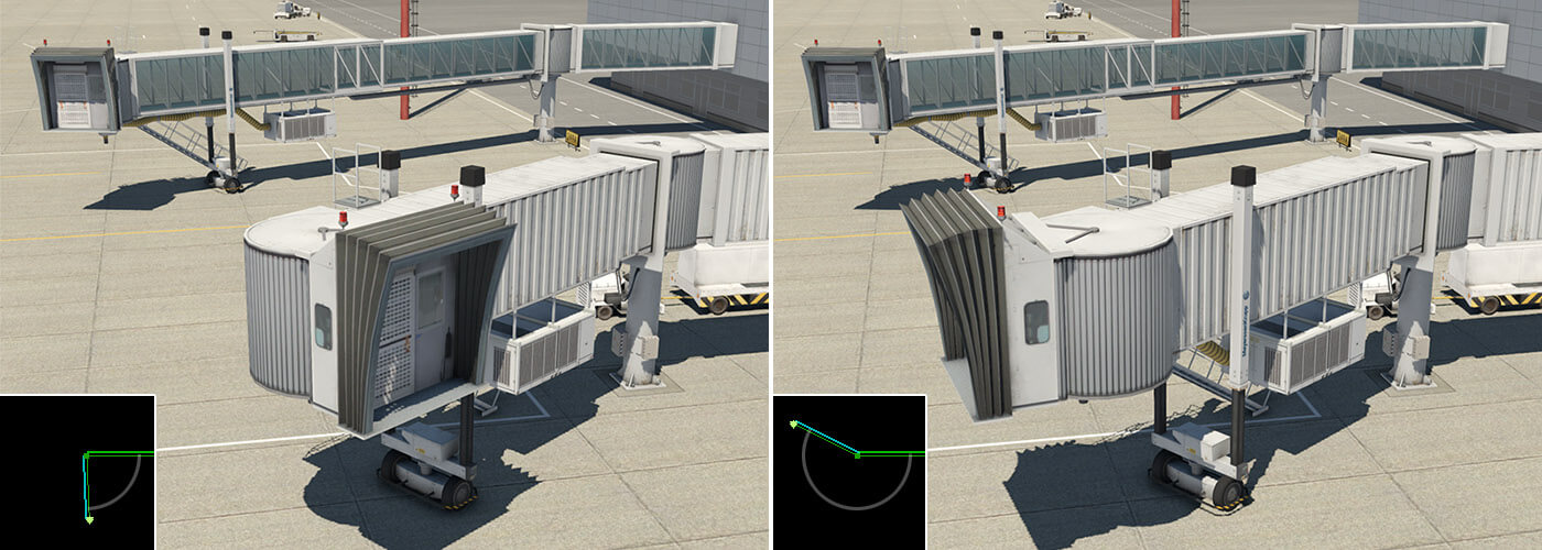
This is the final segment in a jetway chain. There is only one option for this segment – “Cabin“. The segment length isn’t important, but keep it in a reasonable range. The cabin object is always displayed at the beginning of the segment. The angle of rotation of the cabin should be approximately in the range illustrated below.
Special Segment – Connection
There is a special vertex (wall-type) named “Connection“. It works the same way as “Rotunda_..” but without the rotunda object itself. You can use this for connections between existing rotundas, or simply between buildings.
Useful hints
– Artists may combine different facades (white, gray, solid, and glass) to achieve, for example, a glass bridge with solid jetway tunnels.
– Glass versions of extension bridges sometimes have issues with transparency. Please DO NOT file a bug, as this is a known limitation of the rendering engine. There is no guarantee the correct draw order will be achieved from all view angles with all objects. Typically you may not see a neighboring extension bridge through a transparent extension. You will also not see a user-aircraft, or dynamic shadows.
This document contains some quick visual tips for avoiding common pitfalls that cause airports to get declined by the Gateway moderator. Situations vary, and these suggestions may not apply in all instances.
In World Editor (WED)
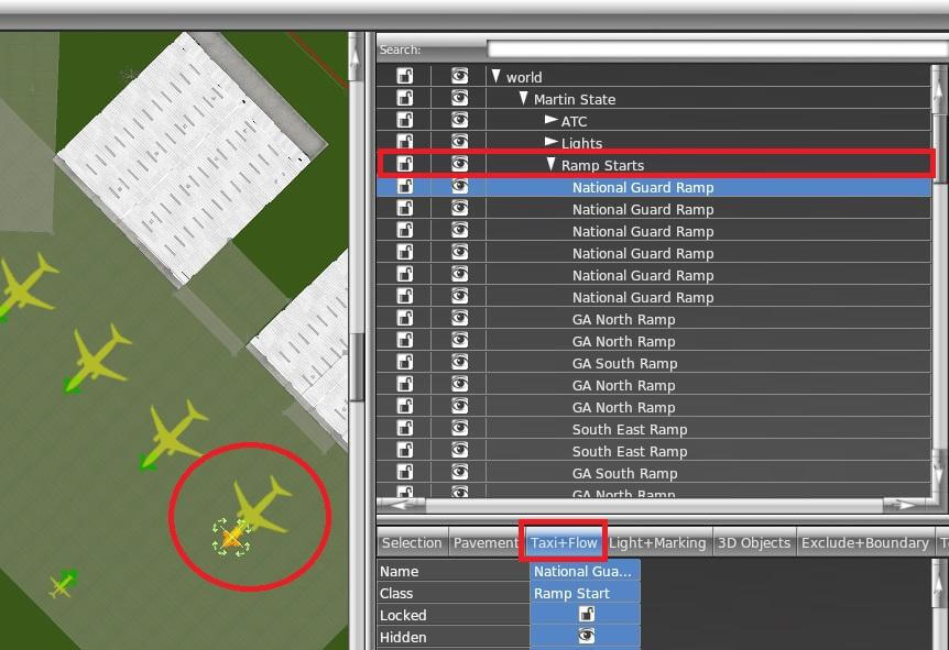
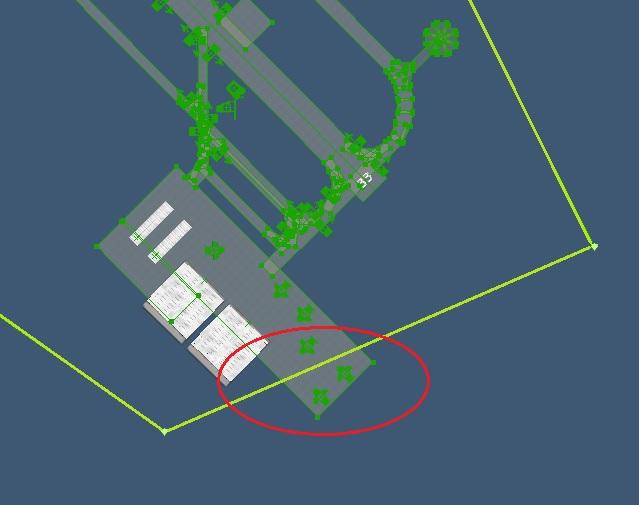
Ramp Starts
Place WED in “Taxi+Flow” Mode when working with ramp starts. Ramp start footprints are displayed which are useful for managing incursions.
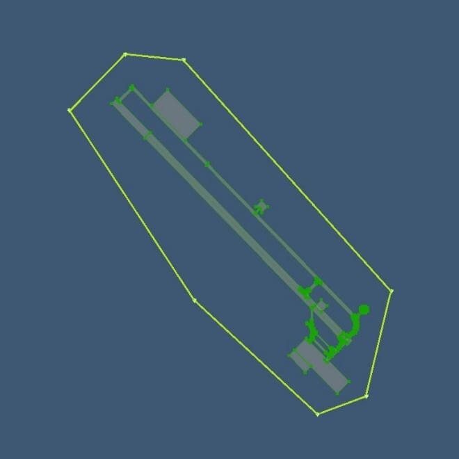
There is a fine line to walk between making the boundary too loose versus too complex. Also ensure that all runways, taxiways and ramps are completely inside the airport boundary.
Realistic AI aircraft traffic at airports requires specifying multiple parameters in the WED scenery file.
Thoughhout all version of X-Plane 11, minimum requirements for successful AI traffic operation at an airport are:
The airport is of type “airport”, i.e. not a “seaport” or “heliport.”
Have at least one ATC frequency of type “Tower” defined.
Note this refers to the “Type” property, not the name given to the frequency entry, which has no relevance for AI operation.
At least one (very preferably multiple) ramp starts of sufficient size is specified:
The size of the largest ramp start (of any type) must be larger or equal to the actual AI aircraft attempting to spawn/land.
X-Plane will not check if that ramp start is actually vacant or the right type – it rather gives ATC authority to make “emergency” decisions like parking a 747 on a Size A “Props” “Misc” ramp start, if none of the size F starts at that airport are available for some reason.
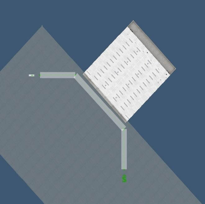
The airport should have at least one ramp start of type “gate/tiedown” and all starts near the runway should be of type ”misc” only. This prevents ATC accidentally spawning AI inside a runway hotzone – which creates a fatal deadlock.
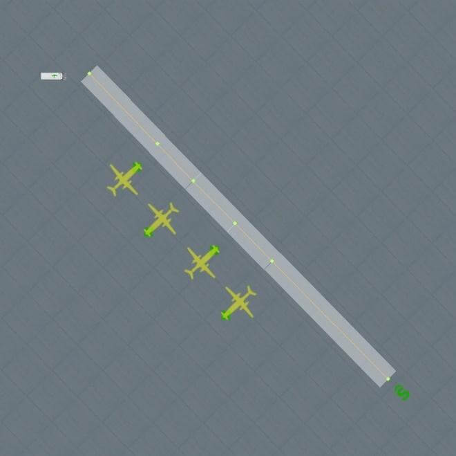
At least one paved runway (surface = “Asphalt” or “Concrete” only) of sufficient width and length is active.
Active means either
there is valid flow specification that meets the current weather condition and it includes a “Runway use” rule for that runway
or no flows are specified. In this case, X-plane will auto-generate suitable flows that activate all runways under any weather condition.
Sufficient width & length depends on the AI aircraft category as in the table below:
Aircraft category
Min. Rwy Width
Min. Rwy Length
Heavy
125 feet
10,000 feet
Fighters
125 feet
7,500 feet
Jets
100 feet
7,500 feet
Turboprops
75 feet
2,500 feet
Props
50 feet
2,500 feet
Anything else
25 feet
1,000 feet
These are all conditions to make AI spawn or attempt to land at the airport.
Note: In older documents – the “has ATC” property was noted as required for AI use. Since X-Plane 10 it is actually officially ignored – so it’s not required. Some airports may even have AI and ATC functionally without an ATC tower frequency defined in WED/apt.dat – if there is a (very rarely) used option to define ATC tower frequencies in an atc.dat file to accompany the scenery.
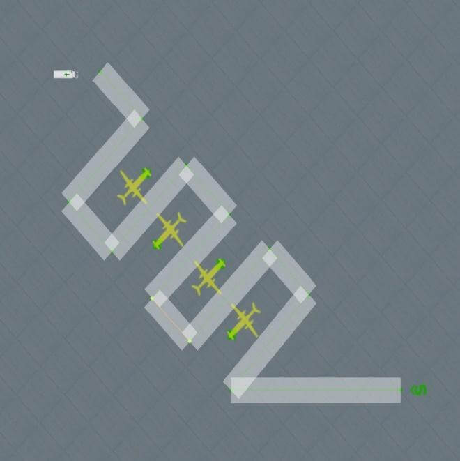
It also implies the actual ramp start types and ATC taxi network details do not prevent AI operation, but only help to make it look more “plausible” once AI are present at the airport. A working ATC Taxi network, either auto-generated by X-plane or specified in the scenery is required to have those AI successfully leave the runway and taxi to/from the ramp starts.
Troubleshooting Tips
To debug problems with AI operations it is recommended to start with hiding all user specified flows and ATC taxi networks in the WED scenery pack. X-Plane will then auto-generate these items, which will result in functional flows & networks, although they will also appear less polished.
By default, the X-Plane log.txt also includes information about AI spawning, flow selection and AI Taxi instructions. The art control atc/debug/log_spawn=1 prints log info on AI aircraft arrival & departure logic. Use the developer console to see this in-sim or view it in the log.txt
WED 1.6 in combination with X-Plane 11.10 or newer now includes an integrated ‘Terminal Kit’, comprising facades and supporting objects that are dedicated to the creation of modern airport terminals. This can be found in the WED library hierarchy at “lib/airport/Modern_Airports/Terminal_kit“. The Terminal Kit is entirely modular, with all parts designed to work together.
The basic concept is for the artist to utilize specific facades for corresponding parts of the building. For example, the kit features one facade for ground floor structures, and another for floors above. This approach asks a little more of the artist, because the facade footprint may need to be replicated multiple times, for each individual floor. However, this method offers far greater possibilities for the design of the structure. Windows, doors or gates may be placed exactly where the artist chooses, without this being restricted by the nature of the adjacent structure.
Key components of the Terminal Kit are prefixed with “term_” so these can be easily filtered in the WED library hierarchy. These are further divided into three logical groups:
The first group (term_building_..) is dedicated to the construction of the main building.
The second group (term_bridge_..) is dedicated to the construction of connecting bridges.
The third group (term_roof_..) is dedicated to the construction of the various roofing options.
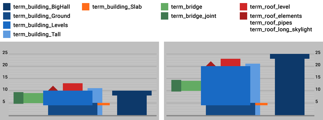
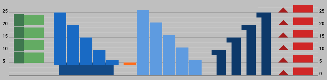
Most facades will comprise several floors, and as you can see, each floor must have an absolute height in units of 5 – namely 5, 10, 15, 20, or 25 meters (one exception is described later).
Diagram illustrating height and elevation options for Terminal Kit facade modules:
Note that roof elements are compatible with height levels (5, 10, 15, 20 and 25 meters). Artists may place them on”_Ground“, “_Levels“, “_Slab” and “_BigHall” modules. However, roof components may not be placed on “_Tall” modules.
Terminal Kit Components
term_building_…
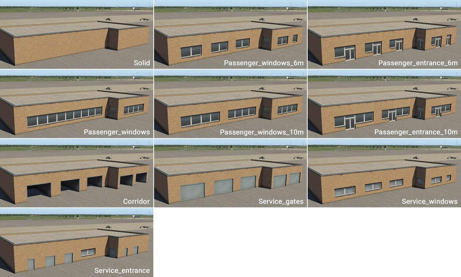
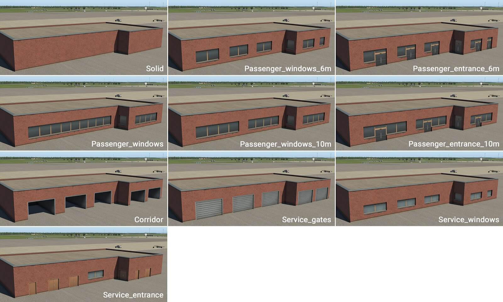
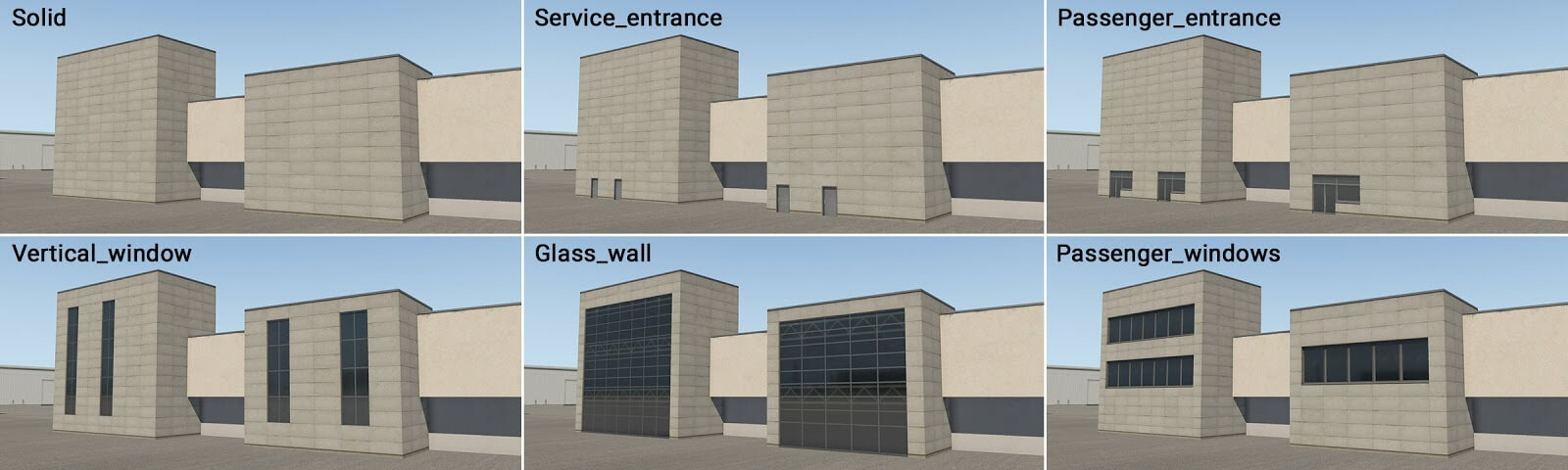
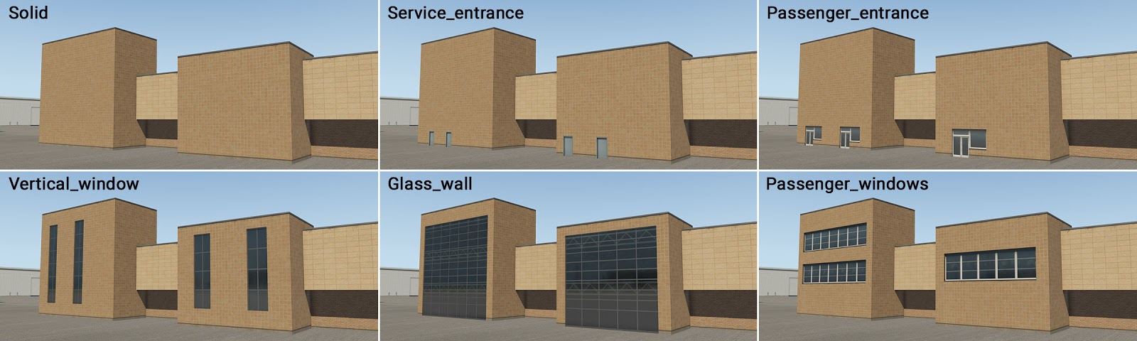
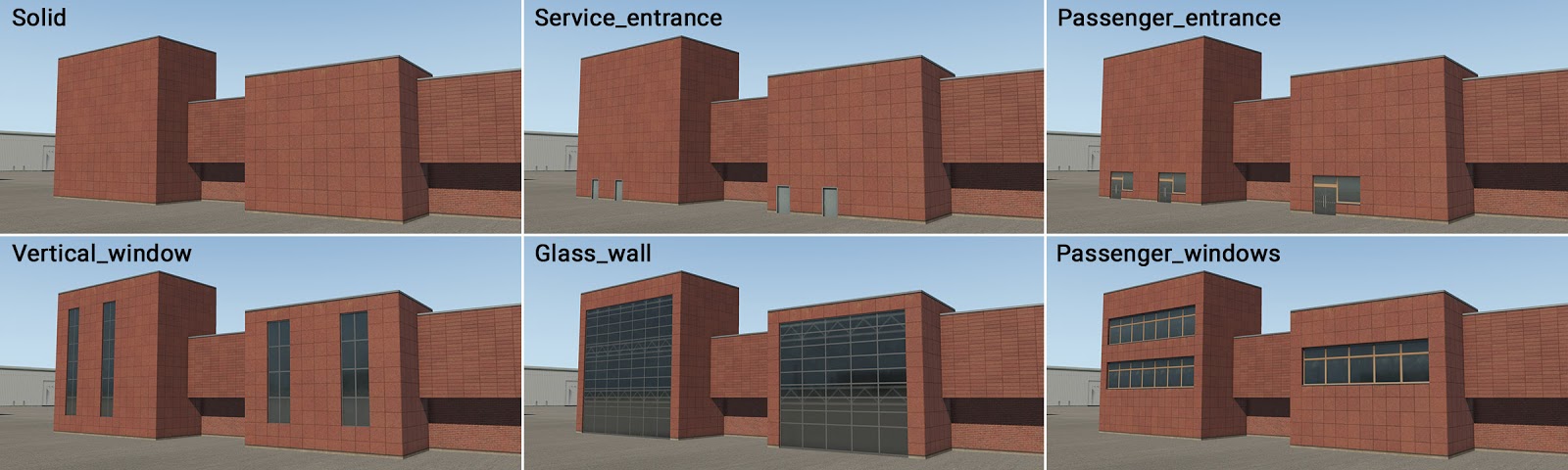
term_building_Ground_XX.fac
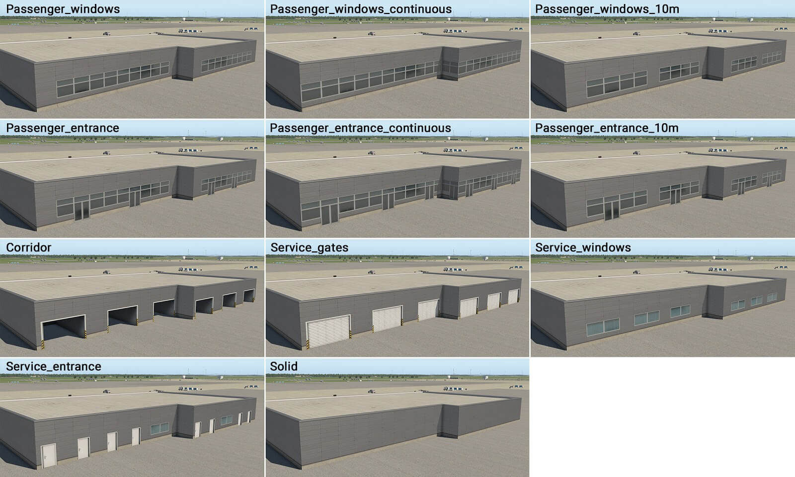
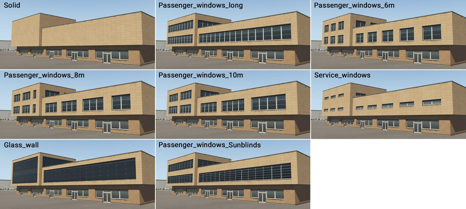
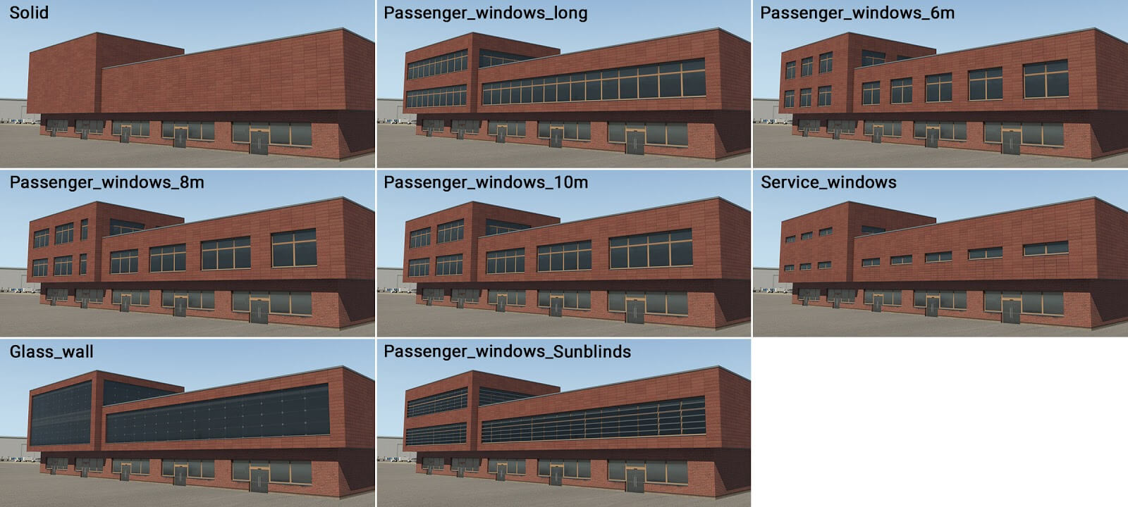
This is the first key component of a building. It has just one ground floor, and its purpose is to replicate the street level of a modern airport terminal. However it can also be used to create any single-floor building, and the artist may use it accordingly. This module has several wall-types–passenger windows, doors, service entrances and gates.
Sometimes three variants of passenger windows and entrances exist. This is a general principle which you will also find in other modules. The first variant (_windows) is designed for whole walls, meaning the facade comprises solid segments at both ends. However, sometimes the artist may require contiguous windows spanning the corners, and this is supported with the “_windows_continuous” variant. A third variant (_windows_XXm) is for long whole walls constructed in units of “XX” meters, with solid segments at either end. Any combination of these variants may be used together, to replicate the desired structure.
There are four stylistic variants in X-Plane 11.20 and newer:
term_building_Ground_01.fac
term_building_Ground_02.fac
term_building_Ground_03.fac
term_building_Ground_04.fac
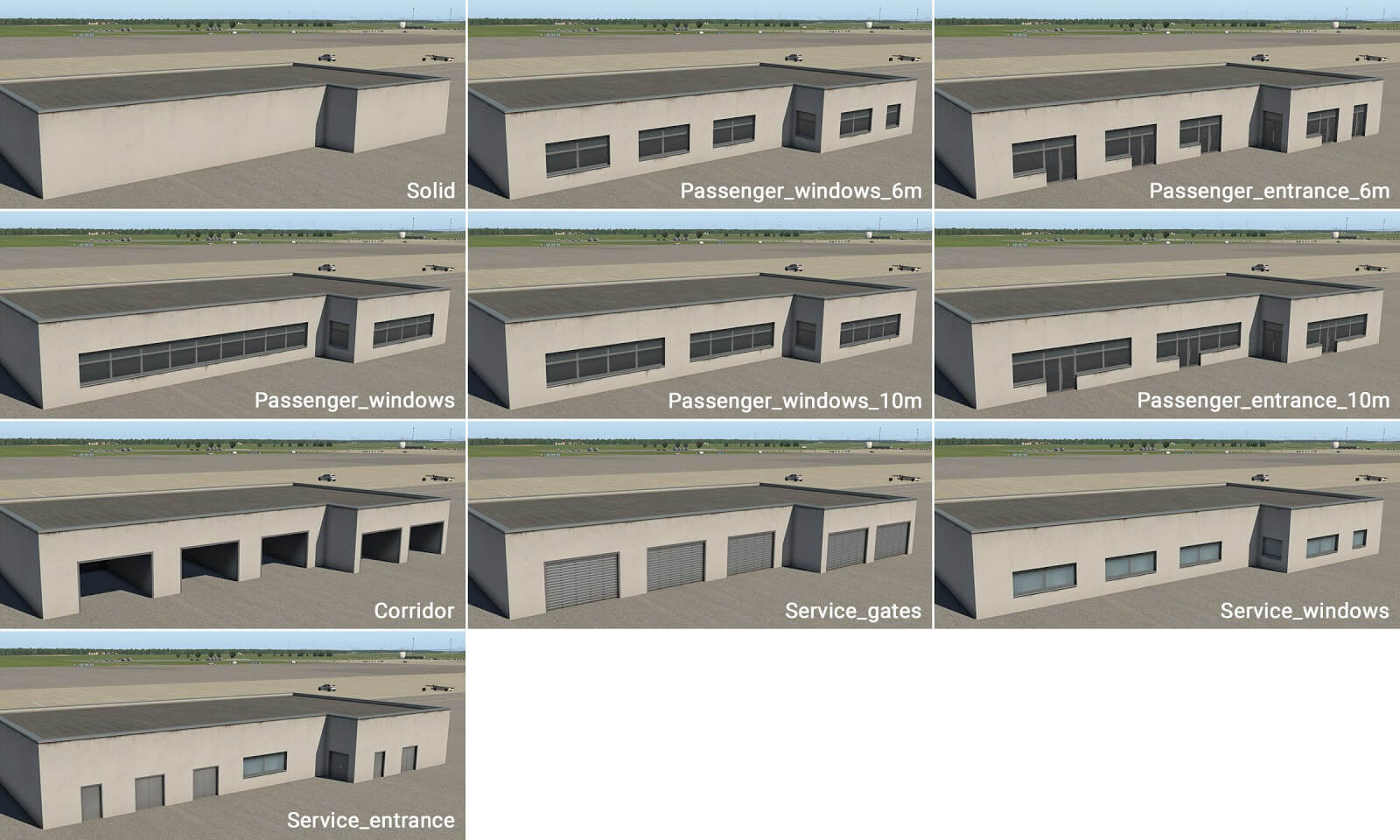
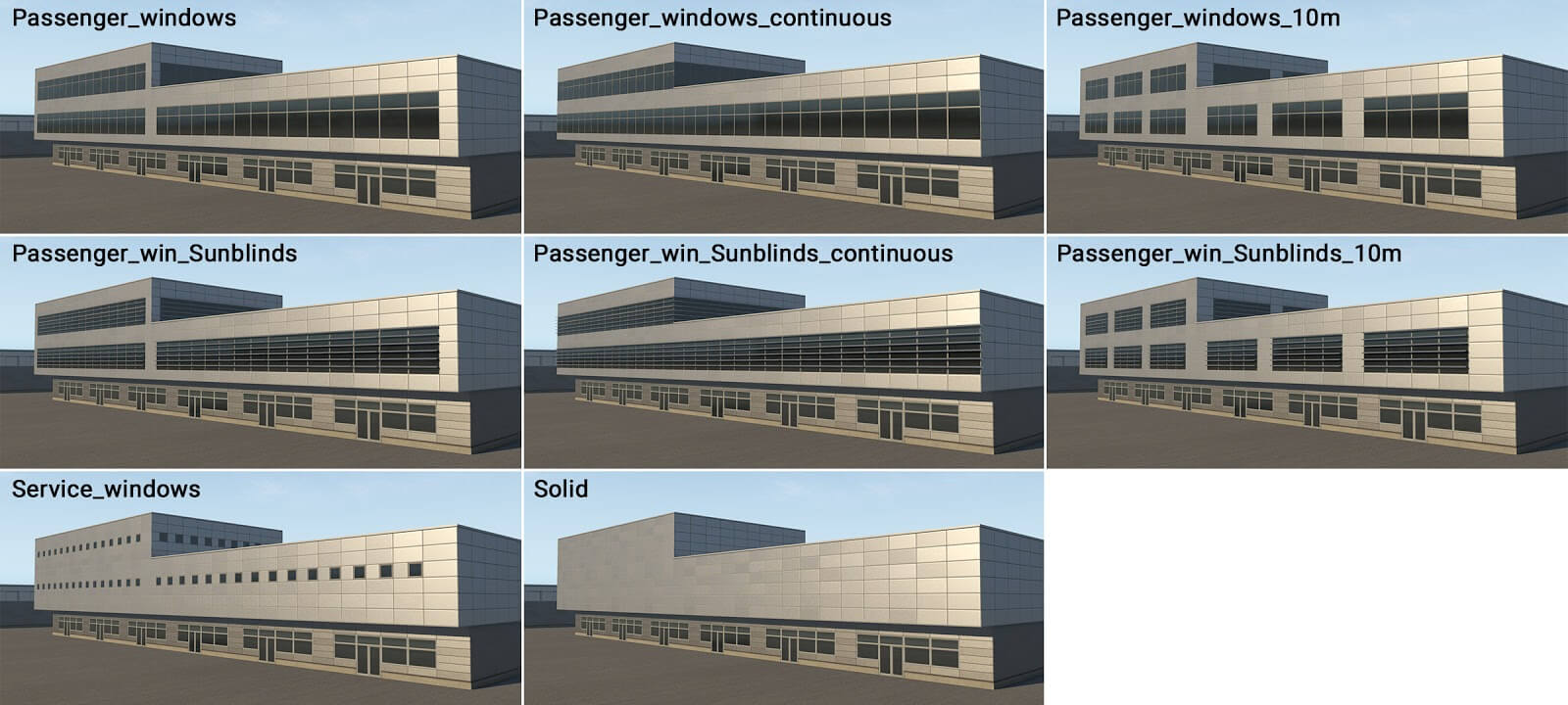
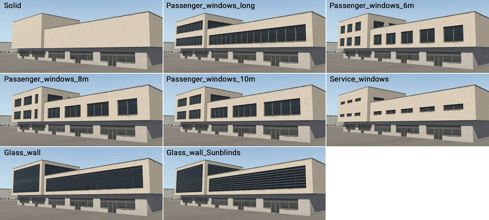
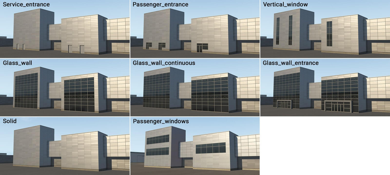
term_building_Levels_XX.fac
This is the second key component of a building. It is designed for (up to) three levels above ground. This module forms the “main” body of the terminal, and also has several types of walls (most of which have windows).
term_building_Levels_01.fac
term_building_Levels_02.fac
term_building_Levels_03.fac
term_building_Levels_04.fac
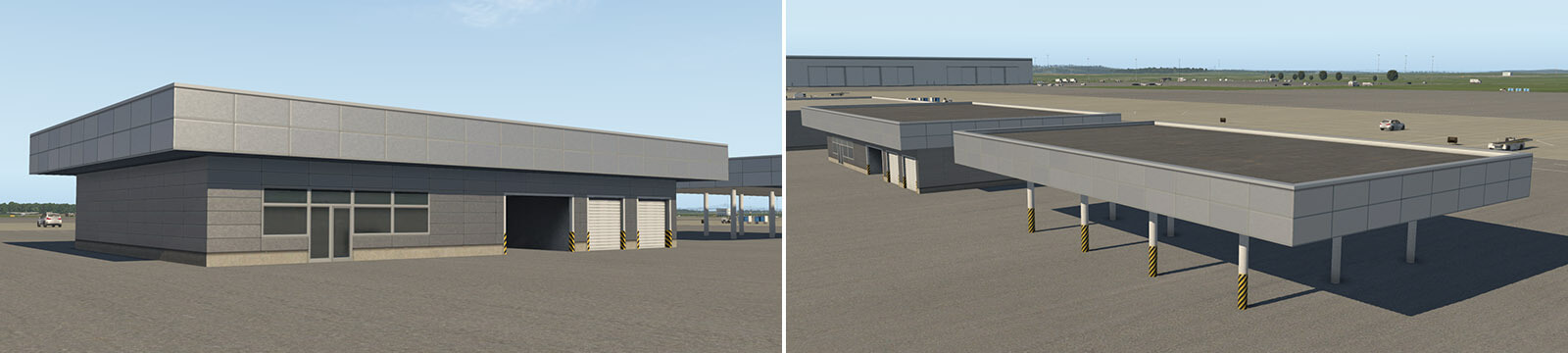
This module also has one very specific usage: When the height is set at 5 meters above ground-level, this component is rendered as a ‘slab’ (no matter which wall type is selected). This can act as a flat roof, and may be used above the ground floor, or with columns (described later). However in this case it is technically higher than a normal floor (6 meters) so artists may not place roof elements on it. Here is an example:
term_building_Tall_XX.fac
This module has various purposes: volume extensions, stair-towers and other vertical parts. It is slightly higher (by units of 1 meter) than adjacent modules, and can be inserted into other basic modules, or used as a stand-alone module.
term_building_Tall_01.fac
term_building_Tall_02.fac
term_building_Tall_03.fac
term_building_Tall_04.fac
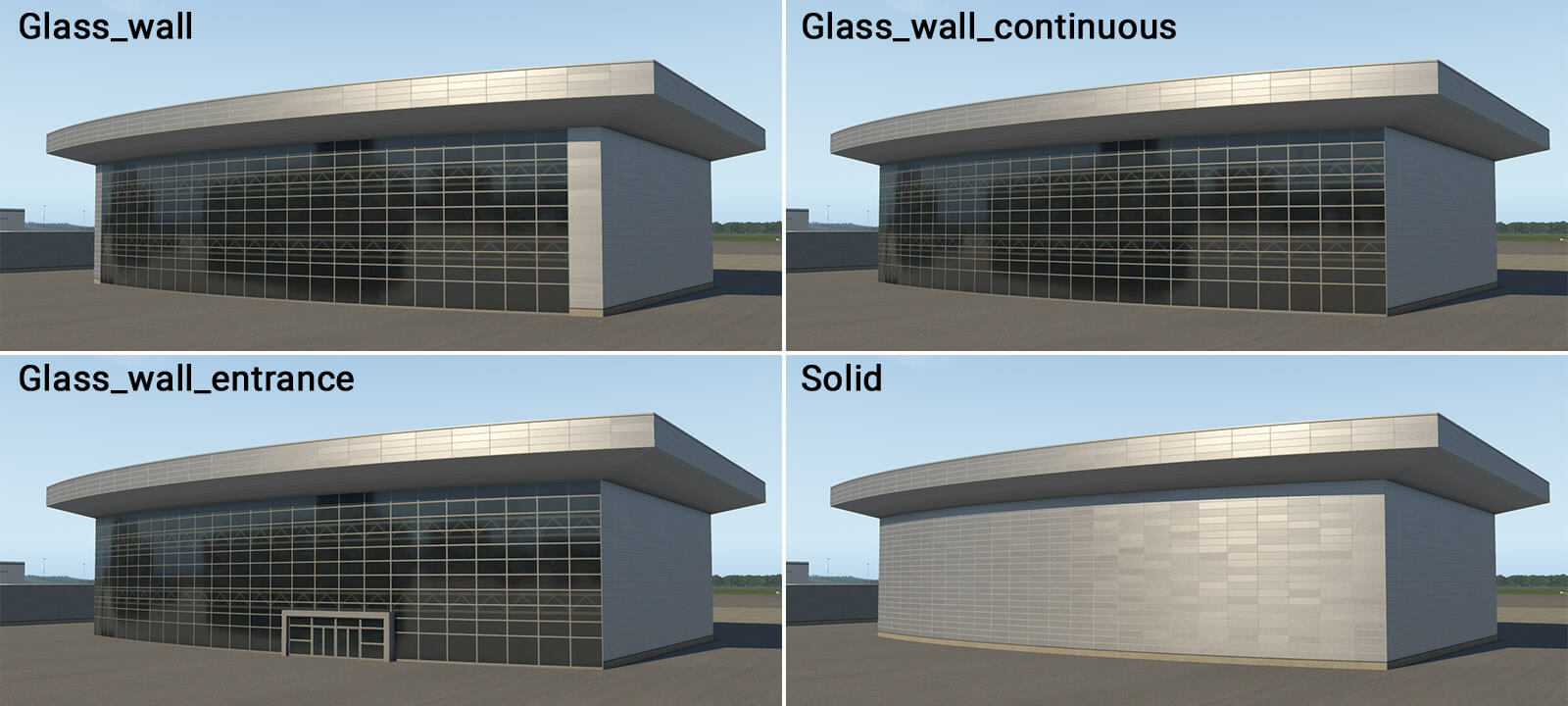
term_building_BigHall_01.fac
This is special module for the creation of large halls with glass walls. It is intended for simple shapes like rectangles, and can’t handle negative corners (concave angles).
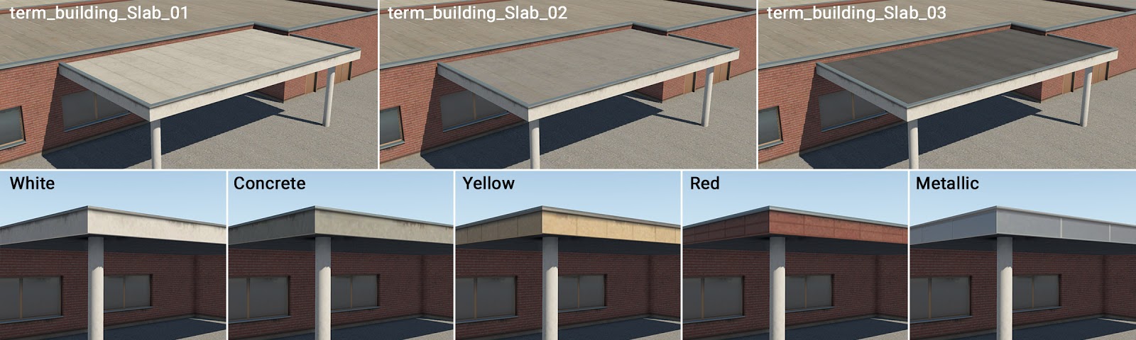
term_building_Slab_01-03.fac
This is another special module for the creation of simple slabs. It is available in three different roof colors, each with five edge-material options. It is also compatible with all roof elements, just like “_Ground” module.
term_bridge_…
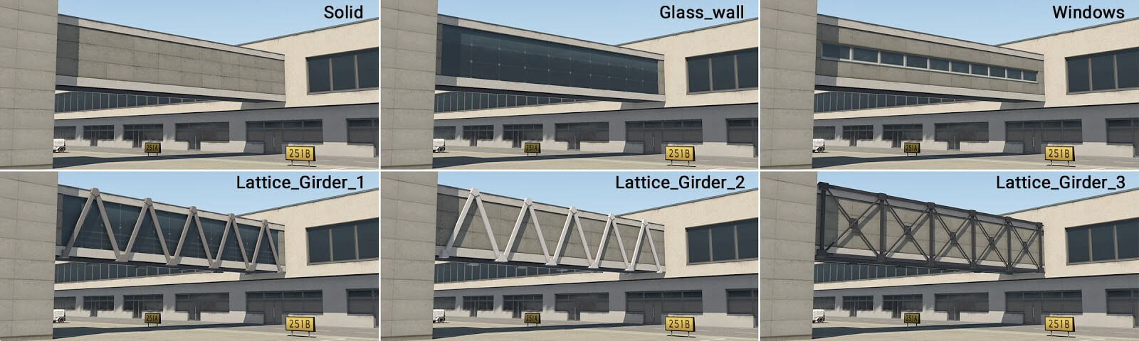
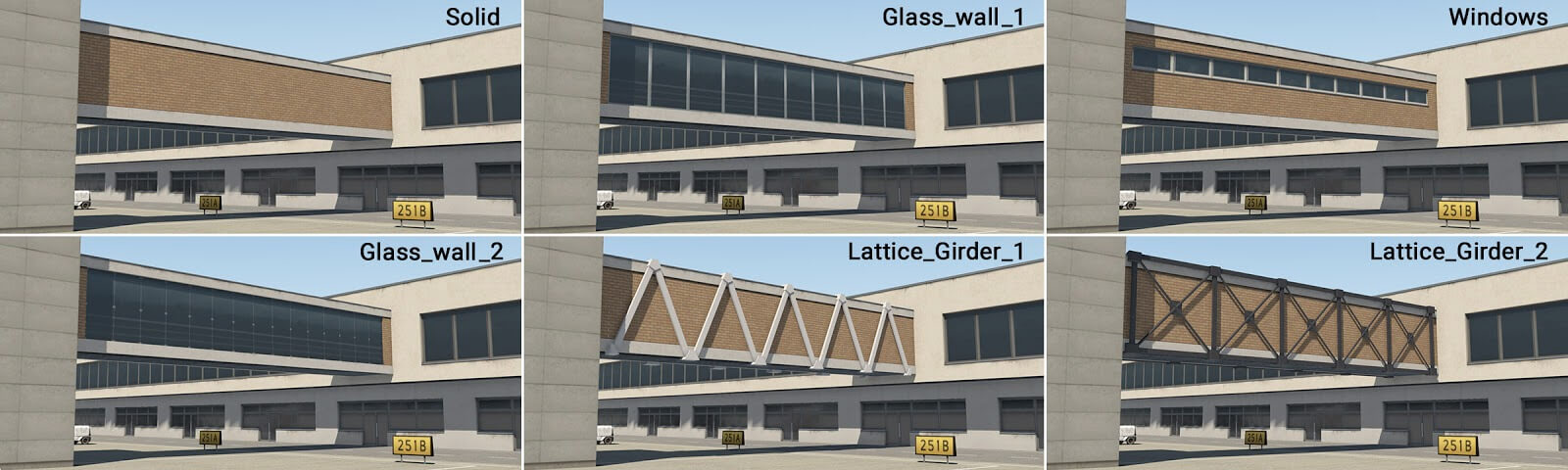
term_bridge_XX.fac
This module is used to create bridges. Technically it is similar in construction to the “_Levels” module, but makes only a single floor. If the artist needs two bridges above each other, this is achieved by duplicating the structure at different heights above ground.
term_bridge_01.fac
term_bridge_02.fac
term_bridge_03.fac
term_bridge_04.fac
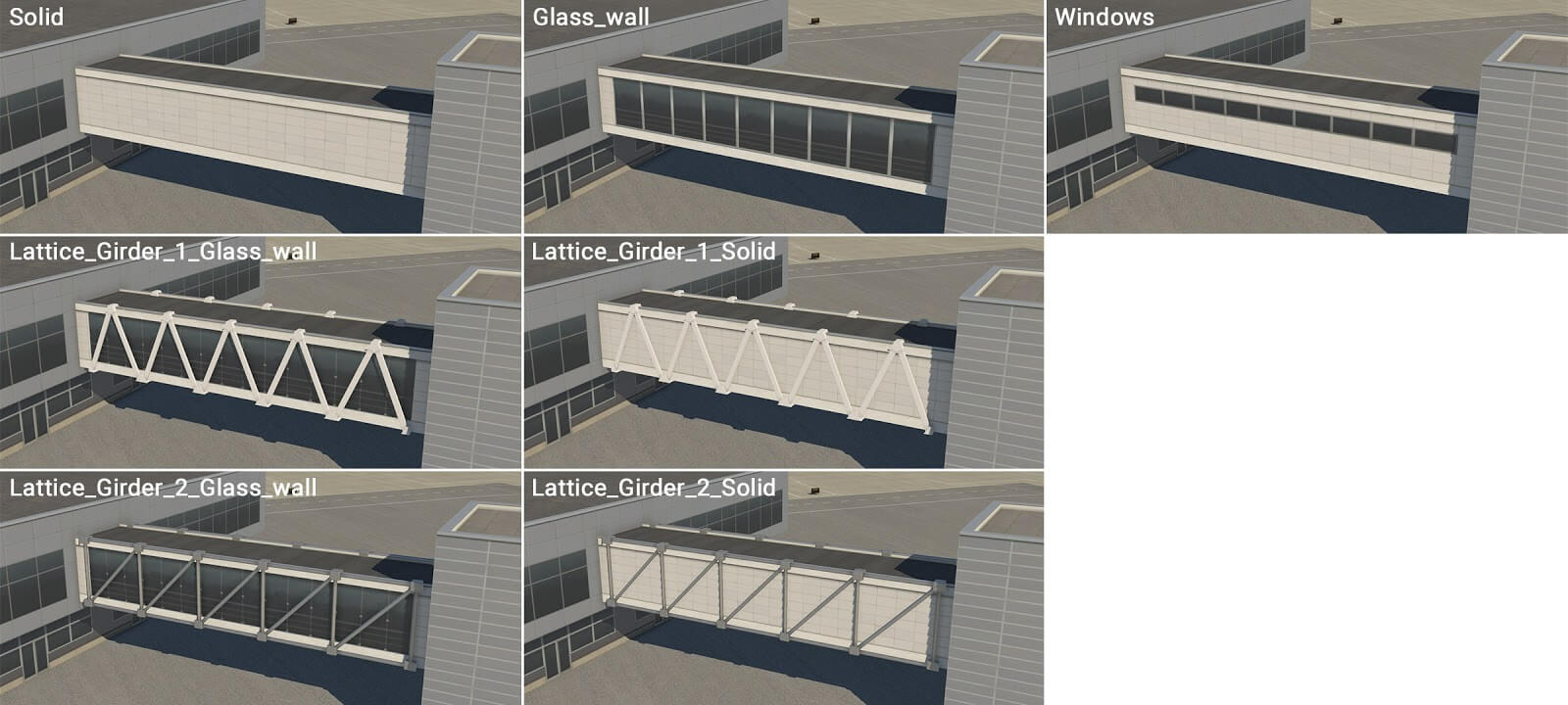
term_bridge_joint_XX.fac
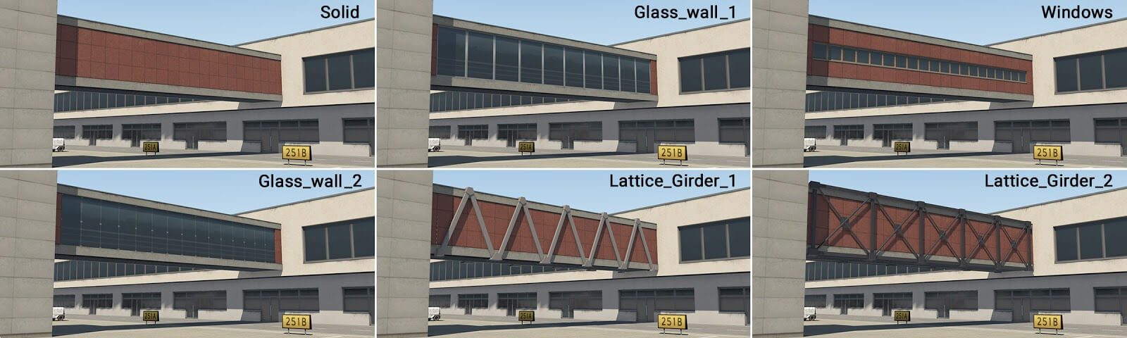
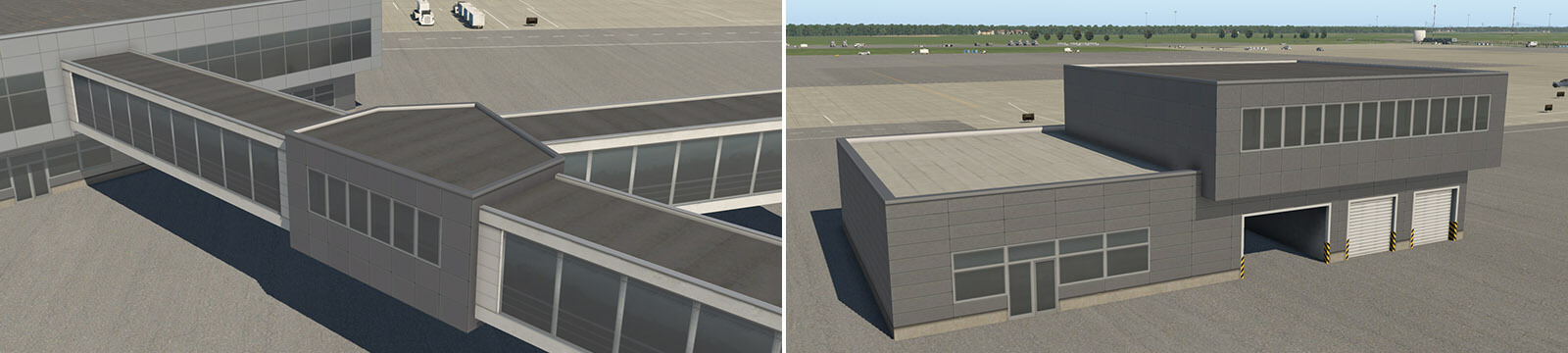
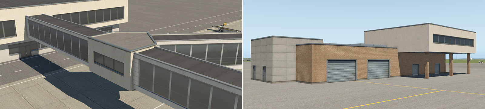
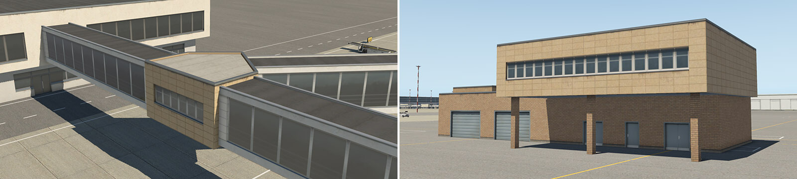
This module is similar to term_bridge_XX.fac, but with a more substantial appearance, supporting just two wall-types – solid, and (very simple) windows. The main usage will likely be situations where two bridge sections are joined together. However, this module may also be used as a second floor, above a ground floor structure.
term_bridge_joint_01.fac
term_bridge_joint_02.fac
term_bridge_joint_03.fac
term_bridge_joint_04.fac
term_roof_…
term_roof_level_XX.fac
This module provides for the creation of roof-superstructures. The module is 3 meters in height, and this is the exception mentioned earlier. The absolute height of this facade must therefore be 8, 13, 18, 23 or 28 meters (as opposed to 5, 10, 15, 20 and 25 meters).
term_roof_Level_01.fac
term_roof_Level_02.fac
term_roof_Level_03.fac
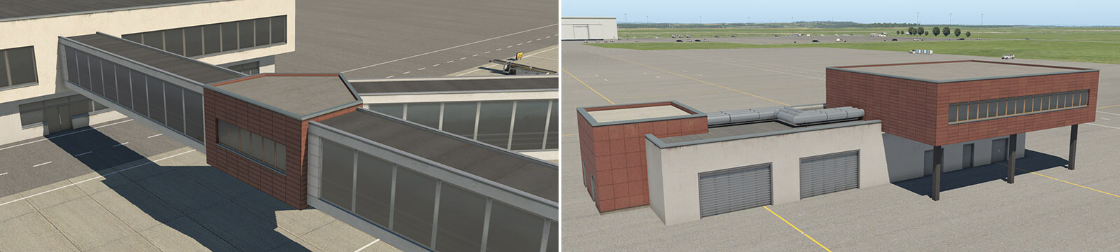
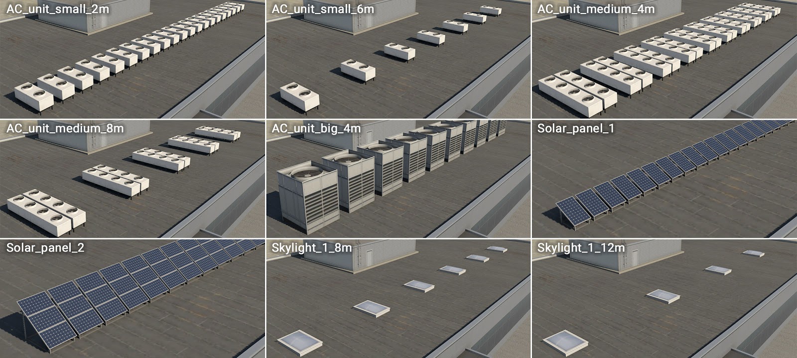
term_roof_elements_01.fac
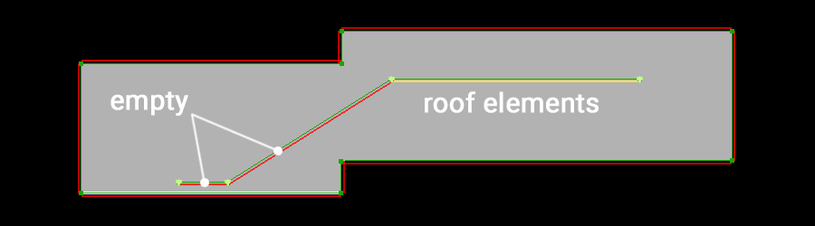
This is very special module. Technically it has invisible walls and roof, and therefore only the attached objects are visible. This module may be used to support various roof elements, like air conditioners, solar panels or small skylights. This module’s facade isn’t ‘closed’, so artists will see a chain of linear-segments in WED. Attached objects are placed at the center of these line-segments.
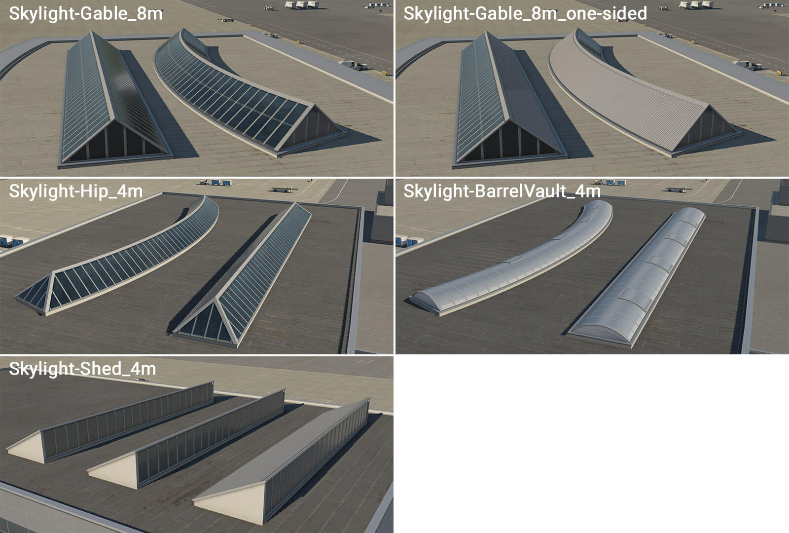
term_roof_long_skylight_01.fac
This is another specific module that forms various longitudinal skylights. This behaves like other WED linear-features, with the line (or chain of lines) itself representing the axis of the skylight.
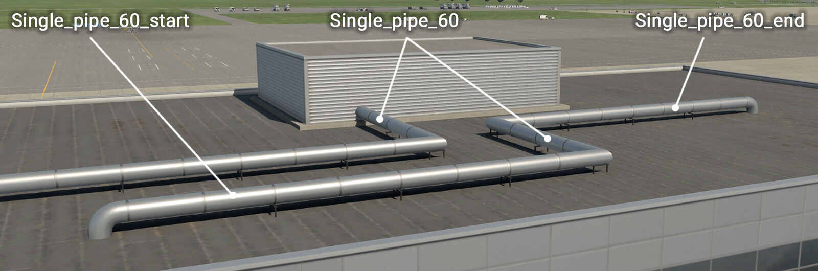
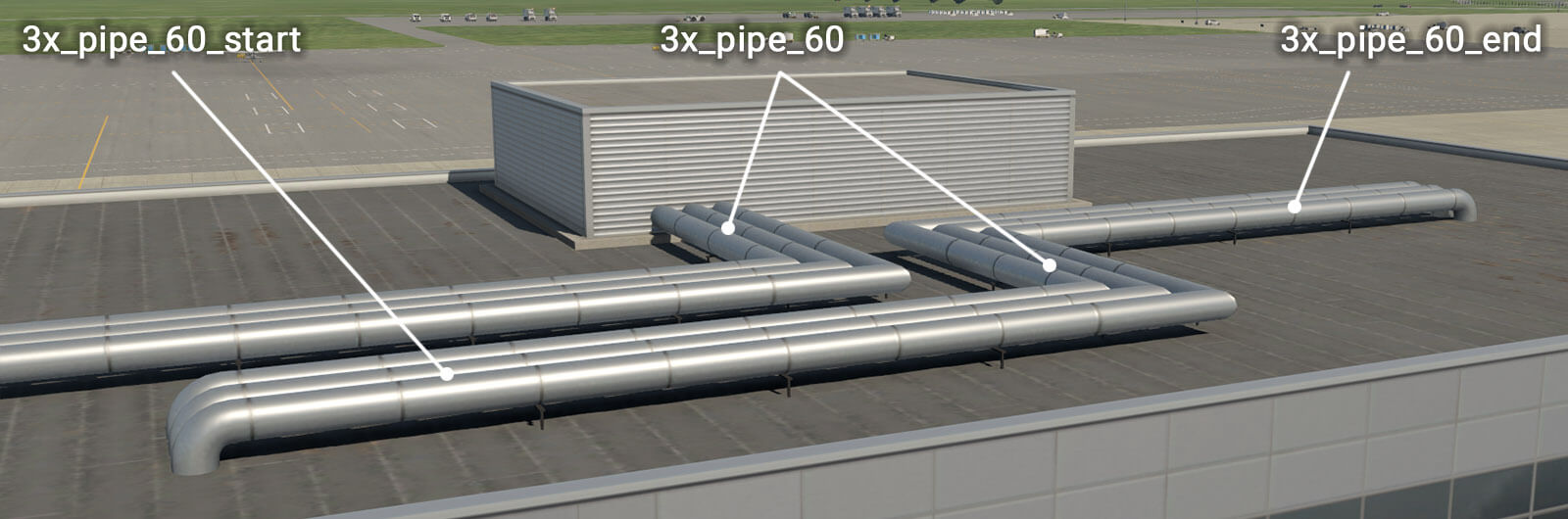
term_roof_pipes_01.fac
The same principle applies here as to the skylights module, except this module is not limited by one segment. The artist may draw any number of segments in a chain. The basic facade wall generates horizontal pipes which can be connected to another module, such as “_roof_level“. However, there are also special walls with a “_start” prefix, and “_end” suffix. This is useful when pipes project vertically from a roof. The direction of the polygonal chain in WED is important here, and this is why the artist must define start and end segments for the facade.
Other objects
There are other useful objects that can be placed manually:
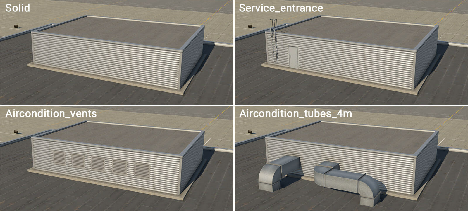
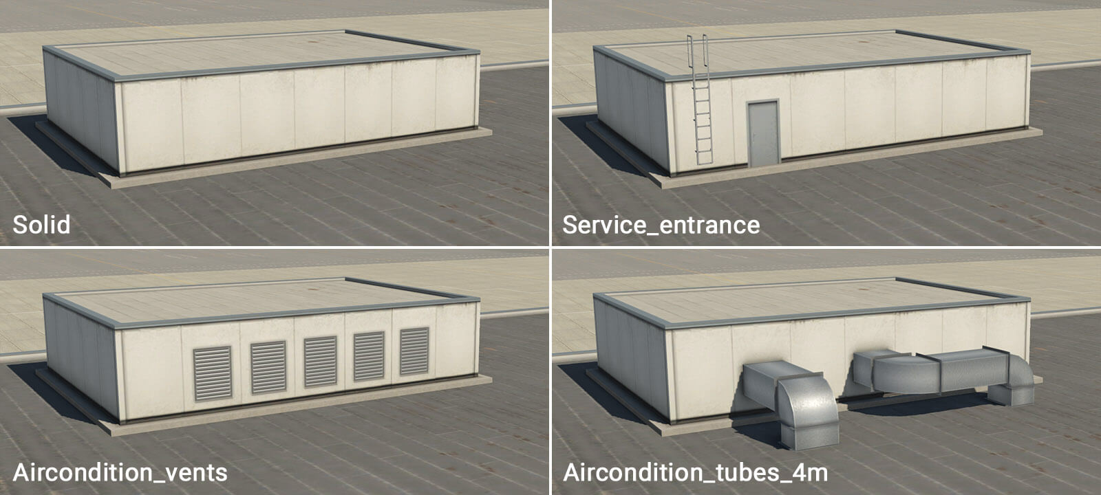
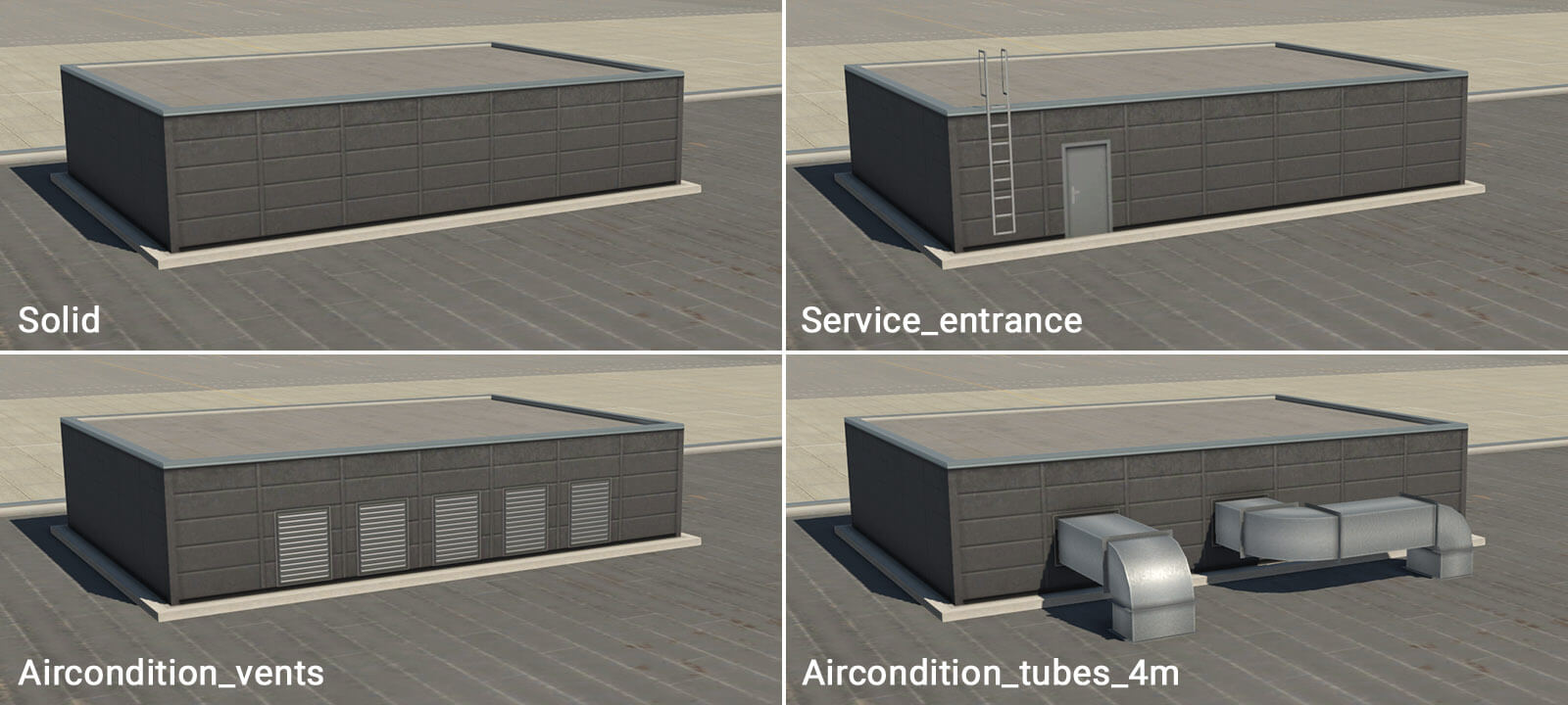
Entrances
Some facades already have walls called “_entrance” but sometimes it will be useful to place them manually. Moreover entrances are generic, and can be used with various facades as needed.
Columns
Additional important objects are columns, and separate ground-floor and upper-floor columns are available. Columns are placed manually where required, to form a plausible structure. Columns are available in two lengths – 4 and 9 meters. Shorter columns may be used under “term_building_Levels” facade and under “term_bridge” and “term_bridge_joint” modules (with a height of 10 meters at the lowest position). Higher columns can be used under bridges or joints (with a height of 15 meters at the lowest position).
Useful hints
-This Terminal Facade kit comprises basic modules of 2-meters in horizontal length. This means that a single metal panel is two meters long. There is no explicit reason to be aware of this, except that it may prove useful when positioning manually placed assets (eg entrances and columns) adjacent to the terminal modules themselves.
-All roof textures have some kind of directionality (appearing as ‘strips’). This is always perpendicular to the FIRST segment of the polygon (the white line in WED). You can rotate segments in WED by pressing Ctrl+R. This is important (especially with bridges) whereby the first segment should be oriented in the direction of the bridge axis.
-Large terminal buildings often have a very complex footprint. Don’t attempt to replicate this complex shape with just a single facade polygon. It’s much better to divide the structure into smaller logical shapes. This also helps when dealing with roof directionality, and where there are large differences in terrain elevation at the extreme ends of the building.
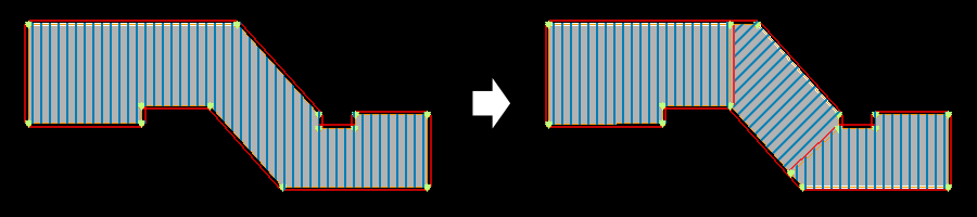
-At times, the terrain may have a significant gradient. This may cause roof elements to ‘float’ above the module below, or sink into it. This is because modules are rendered at the exact height of the center of the first polygon segment. To control for this, some roof modules have an “empty” wall. The artist may start the module chain with an “empty” segment, near the center of the first segment of the underlying module. The artist then draws the second empty segment in the desired location of the (visible) roof element, and this should render at the correct height.
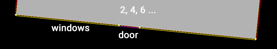
-When an artist requires doors, gates or corridors at exact locations in a long module wall, this may be accomplished by the insertion of a node, and a change in wall-type (even in straight segments). Keep in mind that basic modules are 2 meters in length, so try to use segments that are approximately 2, 4, 6 or 8 meters long. This helps avoid unwanted stretching.
-The height of one metal panel isn’t technically one meter, but actually 96 centimeters. The reason for this is related to jetways, but not important to artists when constructing the terminal modules. Likewise, the exact height of floors are actually 4.6 m, 9.4 m, 14.2 m, 19 m and 23.8 m.