World Editor Manual
Last updated:
Introduction and Setup
About This Manual
This is version 1.30 of the manual for WorldEditor. To use this manual, you can jump to a section by clicking its title in the table of contents on the side. Clicking on terms highlighted in blue like this will take you directly to the relevant text or section. To search for a specific term or set of words, press “ctrl” (“command” on a Mac) + “f” to be taken to the term anywhere in the document. For a PDF version of this manual, use an HTML to PDF converter such as pdfcrowd.com.
Introduction to Scenery Development in X‑Plane
What the Scenery System Does
Scenery in the X‑Plane simulator can include essentially everything outside the aircraft. X‑Plane is designed specifically to enable users to create and modify scenery themselves. This means that, with a little ambition, a home user with no programming experience could design, say, a realistic version of their home town. This model of My Town, USA could then be easily incorporated into the X‑Plane simulator so that upon flying from Neighboring Town, USA into My Town, the scenery seamlessly and transparently moves into the super realistic scenery. These scenery packages can be even be distributed on the Internet so that anyone using the X‑Plane desktop simulator can download and install them.
What the Scenery is Made Of
Scenery in the X‑Plane desktop simulator is made up of both scenery files (DSF files) and text files that describe the various entities in the scenery package. This includes object files for describing buildings, network files for describing road patterns, forest files for describing vegetation, and so on.
In our scenery system, the world is divided into 1 degree latitude by 1 degree longitude tiles, each one of which is defined by one file. Custom scenery is stored in packages, or folders which contain all relevant files. Objects (in the form of OBJ files) can be placed at any location. These objects are most commonly buildings, but they could be houses, airplanes, or even people—X‑Plane doesn’t know the difference. In addition to these custom objects, custom terrain textures may be used to create orthophoto-style scenery.
Available Tools
The X‑Plane scenery development kit contains the following:
- A set of open-source, cross-platform tools for creating scenery
- Specifications for all X‑Plane-specific file formats
- Documentation for the tools, including tutorials
The new scenery generation tools make extensive use of open source libraries; in order to comply with those licenses and to give back to the open source communities that make the new scenery possible, all of the new scenery tools have been released in source code as well as binaries. If you are a programmer interested in working with the scenery, we recommend working within the source code bases for these tools, as they already solve a number of problems relating to in-memory storage and processing of the new scenery.
The Scenery Creation Community & Additional Resources
The moderated yahoo mailing list, x-plane-scenery, gives scenery authors a place to discuss technical issues regarding the creation of scenery. The group home page has both a “join” button (if you have a Yahoo ID) and mailing addresses to join the group without a Yahoo ID.
X‑Plane.org has web-based forums, including a forum dedicated to scenery creation. Additional guides, tutorials, tips and tricks can also be found on the X‑Plane Developer site, including a 13 part video tutorial on airport creation.
Future Compatibility
The X‑Plane 8/9/10 scenery file formats differ from the old X‑Plane 7 formats in that they are open-ended; they can represent almost any configuration of scenery as long as a tool can create it. With X‑Plane 7, to implement new features with the scenery, the format had to change. Since X‑Plane 8, the format can represent almost anything. This means that the format will not change as we develop new scenery technology. Also, third party programmers will be able to design new scenery creation tools without being limited by our file formats, and it may even be possible to convert scenery from other flight simulators.
What Is WorldEditor, and What Can It Do?
WorldEditor (or WED) is the scenery creation and editing tool for the X‑Plane flight simulator. It is designed to be a graphical tool for editing scenery overlays. It is able to:
- create custom airports or custom scenery,
- customize a local airport using built-in airport elements,
- customize the air traffic control flow at an airport, and
- output scenery or airport data files which can be shared with the community.
WED is not used to edit base terrain meshes, the files which give shape to terrain in X‑Plane. To edit these files, use MeshTool, a command-line tool to build base meshes from raw data. WED is also not used to edit or create 3-D models of aircraft, buildings, or other objects in the world. For information on using 3-D modeling programs such as AC3D or Blender to create X‑Plane objects, see the Third-Party Development section of the X‑Plane Wiki, or download the Plane Maker manual.
Downloading and Installing WorldEditor
To use WorldEditor, do the following:
Visit the X‑Plane Developer site and download the version of WED for your operating system. Save it to a location you will be able to find it, like the Desktop. Note that at the time of this writing, WED 1.2 is final.
Extract the WED executable from the ZIP file you just downloaded and save it somewhere you will be able to find it later (you can put it in your X‑Plane directory, but this is not strictly necessary).
Launch WED by double-clicking on it.
If this is your first first time launching WorldEditor, you must point the application to your X‑Plane installation. To do this, click the Choose X‑Plane Folder button in the bottom right of the window as seen in Figure 1. In the new window that opens, navigate to your X‑Plane folder, and click Select or OK.
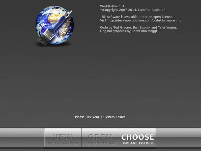
Figure 1: A first launch of WorldEditor, with all options disabled except for “Choose X‑Plane Folder”
X‑Plane Scenery Concepts
X‑Plane scenery comes in “packs.” A scenery pack is simply a self-contained folder with all elements of a scenery. These include:
- DSF files, which contain the location of scenery elements,
- apt.dat files, which contain airport taxiway and ATC shapes,
- art assets, which define how things look, and
- an optional library.txt file, which shares art assets with other scenery packs.
For more information on the contents of a scenery package, see the appendix Anatomy of the X‑Plane Scenery System.
WorldEditor creates its own file, called earth.wed.xml, in the folder that represents your scenery pack. All of your work in WED is saved in this file. You then “export” your work, which creates the final scenery in a format usable by X‑Plane. This workflow is quite similar to creating on a multi-layer Photoshop document, then saving a copy as a PNG for use outside Photoshop (emailing, posting to a website, etc.). Just like in Photoshop, the format used for editing a scenery file includes more information (and takes up more space) than the format used as output for an end-user.
WED’s own files have the advantage of letting WED save scenery information that isn’t normally present in a scenery package: hierarchy information, object names, and window positions. However, it has a few major impacts on your work:
You must “build” your scenery pack (which exports all of your work to the X‑Plane file formats) before you will see anything in X‑Plane. Doing a normal “save” in WED won’t create real X‑Plane scenery. To export a scenery pack, open the File menu and click Export Scenery Pack, or press Ctrl+B on the keyboard (Command+B on a Mac). In addition, as of version 1.3, you can export directly to the Airport Scenery Gateway. We discuss this more in the section Exporting the Scenery.
Building scenery does a “save-as” to your scenery pack with WED’s latest work—this can overwrite and destroy existing scenery if you already have a package in your Custom Scenery folder with the same name (e.g., if you have previously exported this scenery package).
Because WED only opens earth.wed.xml files, if you have created scenery packs in other programs like Overlay Editor, or if you want to open scenery packs for which you don’t have the earth.wed.xml file, that scenery must be imported before you can edit them. See the section Synchronizing with Other Editors for details on how to do this.
You must set an export target. Basically the export target sets the oldest version of X‑Plane that can use the output scenery pack (though you also have the option of setting the Global Airport Database as your target.) When the export target is set older, the relevant new features in WED are then not allowed. For example, if you set an export target of version 9.70 of X‑Plane, then you will see an error exporting ATC data because v9 of X‑Plane can’t accept ATC data. The Validate command, which you can access either through the file menu, or by pressing Shift-Ctrl-V on the keyboard (Shift-Command-V on a Mac) validates the WED file based on the current export target.
Using the WorldEditor Interface
The WorldEditor interface has the following features (where numbers correspond to those in Figure 2):
- Library pane
- Library preview pane
- Toolbar
- Tool defaults settings
- Map pane
- Hierarchy pane
- Editing tabs
- Scenery package list (seen in Figure 3)
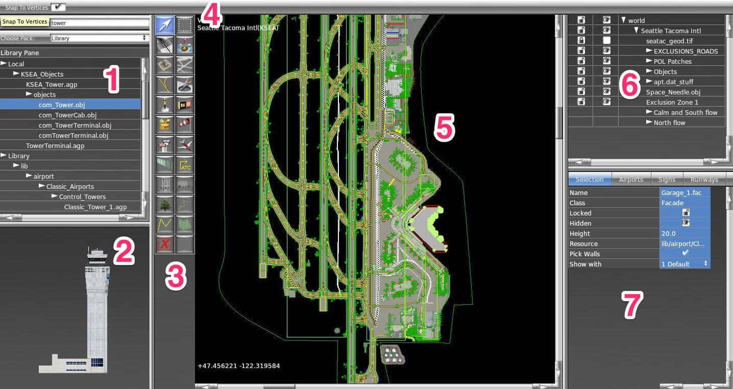
Figure 2: A typical WorldEditor window, whose components are numbered to correspond with the preceding list
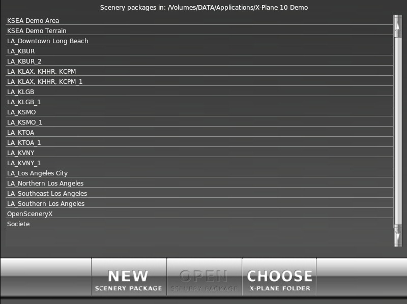
Figure 3: The scenery package list, visible when launching WED
The Scenery Package List
The scenery package list, shown in Figure 3 above, is the window visible when you first launch WED. By clicking a package name from this list, then clicking the Open Scenery Package button, you can open an existing scenery package. Alternatively, you can use the New Scenery Package button to create a new custom scenery pack.
The Map Pane
The map pane, numbered 5 in Figure 2 above, takes up the largest portion of the window by default. This is the pane that gives a bird’s-eye view of the scenery package as it stands. By mousing over the map pane and scrolling with your mouse, you can zoom in or out (note that the zoom will center around wherever your mouse is located—if you place it in the bottom right and scroll up, you will zoom in toward the bottom right of the window). If you ever lose your place in this view, you can click View from the menu and select Zoom World (to zoom out to where you can see the whole planet) or Zoom Package (to fit the view to the scenery package itself).
In this pane, you can visually add, move, and remove elements from the scenery package. The effect of clicking on an element in the map pane depends on what tool is selected in the toolbar.
The Toolbar
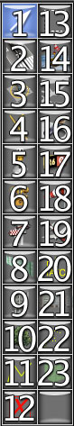
Figure 4: The tools in the toolbar, numbered in correspondance with the list to the left
The toolbar, numbered 3 in Figure 2 above and seen in Figure 4 to the right, selects the “tool” currently in use. Different tools are able to modify different types of things in the map pane. These are as follows (moving top-to-bottom, left-to-right as in Figure 4):
- Vertex tool

- Used to select and manipulate vertices or any other type of “point” (such as runway endpoints, points in a facade, 3-D objects, object headings, etc.). You can either click the point directly, or click and drag to create a box within which all points will be selected. Depending on the point’s type, holding Alt when you click may change the tool’s behavior (e.g., an Alt+click on a point in a facade allows you to create a curve from that point).
- This tool is similar to the marquee tool (both are for manipulating existing objects), but importantly different: the vertex tool if for points, while the marquee tool is for whole entities. Generally, it is a good idea to use the vertex tool to manipulate individual points and entities, and use the marquee tool to move, rotate, and scale selected items.
- Shortcut key: v
- Vertex tool
- Runway creation tool

- Used to graphically add runways, blastpads, and displaced thresholds. Click somewhere on the map to set the first endpoint of the runway, then click again to set the second endpoint.
- Shortcut key: r
- Runway creation tool
- Helipad tool

- Used to graphically create helipads.
- Shortcut key: h
- Helipad tool
- Taxiline tool

- Used to create taxiline paths for runways.
- Shortcut key: l
- Taxiline tool
- Light fixture tool

- Used to place light fixtures such as PAPI/VASI or wigwags.
- Shortcut key: f
- Light fixture tool
- Airport beacon tool

- Used to place rotating airport beacons.
- Shortcut key: e
- Airport beacon tool
- Tower viewpoint tool

- Used to set control tower viewpoints (the point from which users in X‑Plane will see their aircraft when they select the Tower Viewpoint from the View menu).
- Shortcut key: a
- Tower viewpoint tool
- Boundary tool

- Used to add fencing (via Bezier polygons) around airports.
- Shortcut key: b
- Boundary tool
- Object tool

- Used to visually place an object (a
.objfile or.agpscene file) of the type currently selected in the library pane (numbered 1 in Figure 2 and described below). For more information on objects, see the section Adding Objects and Auto-Generating Scenes later in this manual.
- Object tool
- Forest tool

- Used to draw forested regions, which may be filled with trees in X‑Plane depending on the user’s forest density settings. The type of trees that will be used depends on the
.forfile resource you specify.
- Forest tool
- Line tool

- Used to draw miscellaneous lines, such as sidewalks, using Bezier curves.
- Line tool
- Exclusion tool

- Used to draw “exclusion zones,” which are lat-lon rectangles that prevent elements of lower-priority tiles (e.g., X‑Plane’s autogenerated cities or forests) from being loaded in the area. For example, if an overlay tile contained placements for custom buildings for Manhattan, the author would also create an exclusion zone around Manhattan that would prevent the default buildings (that ship with X‑Plane) from appearing there.
- Exclusion tool
- Marquee tool

- Used to drag a rectangle to select an entity (i.e., all the points that make it up), or to click on an entity to select it.
- Shortcut key: m
- Marquee tool
- Sealane tool

- Used to create sealanes with buoys.
- Shortcut key: s
- Sealane tool
- Taxiway tool

- Used to create taxiways via closed Bezier paths.
- Shortcut key: t
- Taxiway tool
- Hole tool

- Used to create holes through which grass (or possibly other pavement) is visible through Bezier taxiways.
- Shortcut key: k
- Hole tool
- Sign tool

- Used to place runway signs.
- Shortcut key: g
- Sign tool
- Windsock tool

- Used to add windsocks.
- Shortcut key: w
- Windsock tool
- Ramp start tool

- Used to place starting points for aircraft.
- Shortcut key: o
- Ramp start tool
- Taxi route tool

- Used to define a route commanded of a taxiing aircraft by air traffic control.
- Taxi route tool
- Facade tool

- Used to draw facade boundaries (from
.facfiles) using Bezier curves. For more information on facades, see the section Adding Facades later in this manual.
- Facade tool
- String tool

- Used to place object strings (a number of otherwise standard
.objfiles along a line, defined for use here in a.strfile).
- String tool
- Polygon tool

- Used for draw miscellaneous polygons (from
.polfiles—often simple textures).
- Polygon tool
For more detail on the tools described above, see the chapter Editing Using the Map Tools.
The Tool Defaults Pane
Numbered 4 in Figure 2, the tool defaults pane changes the settings for the currently selected tool. The available settings vary by the tool. For instance, the vertex tool’s only option is whether or not to snap to vertices (that is, to “jump” to existing points when dragging some vertex). The runway tool, on the other hand, can specify the runway’s surface and shoulder material (concrete, grass, snow, etc.), the roughness of the runway, the presence of centerline lights, and so on. For many tools, you can change the default resource by selecting that tool, then clicking an asset in the library pane (described below) that is usable by that tool.
Before using any tool, set up the preferences first and you won’t have to edit later. When you change the defaults for a tool, WED will remember those changes so that the next time you use the tool, it will be set up the same way. This saves time when drawing many similar types of things.
The Library Pane
The library pane, numbered 1 in Figure 2, displays art assets currently available for inclusion in the scenery. Here, you can browse through the files in the X‑Plane library using their virtual paths. (For our purposes, a full understanding of the library system is not required, but for further reading, see the appendix About the X‑Plane Library System.) Selecting an asset will also select an appropriate tool—for instance, if you select a .obj file, the object tool will become active, and if you select a .for file, the forest tool will become active.
If you are looking for a specific asset, you can search the library using the “Filter” & “Choose Pack” boxes at the top of the pane. Click the “Choose Pack” box to display a drop down list of available library packs, and select the pack you’d like to search within. Next type a search term in the “filter” box to see all available objects that include that term within the pack. For instance, if you were looking for a specific ATC tower, you might type “control_tower,” with the airport scenery pack selected. The lbirary pane would show the Classic_Tower_1 object, among others.
The Library Preview Pane
The library preview pane, numbered 2 in Figure 2, shows an accurate, real-time preview of some (but not all) art assets. When you select a .pol file in the library pane, the pane will be filled with the texture defined by that polygon asset. When you select a .obj or .agp file in the library pane, a 3-D preview of the object or scene will appear in the preview pane. By clicking and dragging this preview, you can change your perspective, and you can zoom in using the scroll wheel on your mouse.
The Hierarchy Pane
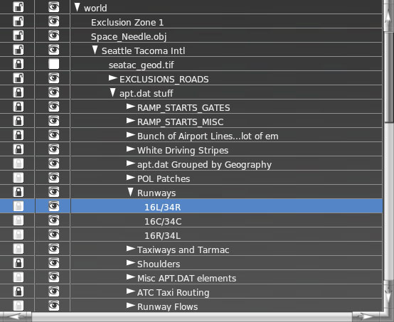
Figure 5: The hierarchy pane in WED
The hierarchy pane, numbered 6 in Figure 2 and shown enlarged in Figure 5, shows every element currently in the scenery package.
Using this pane, you can select an element or group by clicking on it. This will highlight that element in both the hierarchy and map panes. By double-clicking on an entity in the hierarchy, you can rename it.
By clicking and dragging an entity in this pane, you can change the order in which objects are drawn: objects and groups higher in the hierarchy will be drawn on top of those lower in the hierarchy whenever they overlap. For instance, in Figure 5, the “Runways” group is higher than the “Taxiways and Tarmac” group, so all elements within “Runways” will be drawn over elements contained in “Taxiways and Tarmac” if they happen to overlap.
To place one or more entities in a group, select them and press Ctrl+G on the keyboard (Command+G on Macs), or select Group from the Edit menu. To ungroup elements (that is, remove a group, leaving all entities the group previously contained at the same “level” as the group was), select a group label and press Ctrl+Shift+G (Command+Shift+G on Macs), or select Ungroup from the Edit menu.
By clicking the lock icon, you can lock an element or group to prevent further visual editing. Note that is applies only to editing within the map pane; changing the element’s properties in the editing tabs (beneath the hierarchy pane, described below) is still possible. Note also that this property applies recursively: if a group in which an element resides is locked, that element will also be locked.
Next to the lock icon is an icon that looks like an eye. This toggles the visibility of an element or group. Invisible elements will not be exported for use in X‑Plane, and will of course not be visible in the map pane.
To delete entities, select them in the hierarchy and press the Backspace or Delete key on the keyboard, or select Clear from the Edit menu.
The Editing Tabs and the Attributes Pane
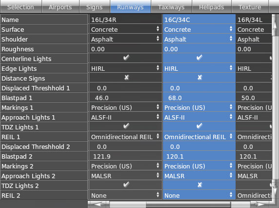
Figure 6: The editing pane in WED
The attributes pane, numbered 7 in Figure 2 and seen in Figure 6, contains a number of editing tabs, which allow for editing of elements based on their type. The first tab, labeled Selection, shows in full detail whatever scenery element is currently selected. Because of this, it changes the properties displayed in order to match the currently selected element.
The Airports tab collects together all airports in the scenery package and allows you to set general information about the airport (its field elevation, ICAO identifier, and so on), and it also allows modification of the communication channels (e.g., UNICOM, ground, or tower) associated with the airport.
The Signs tab (more appropriately labeled “Lights, Signs, and Beacons”) collects together all lights (PAPI, VASI, and wigwags), taxi signs, and beacons. You can change the type of each of these objects, and (depending on what category the element falls under) the size and angle.
The tab labeled Runways (seen in Figure 6) allows for easy access to all runway elements. All available properties of the runways can be changed from here, including the material that makes up their surface, the presence of lights, the size of a blastpad, and so on.
The Taxiways tab provides similar (but more limited) functionality for taxiways. The only editable properties of taxiways are their surface type, roughness, and texture heading (the distance, in degrees, that the texture is twisted, which may be useful for adding variation in the appearance of the taxiways).
The Helipads tab allows editing of all helipads in the scenery package. Features that can be changed include surface type, markings present, and roughness.
Creating Airports and Overlay Scenery
This tutorial steps through the creation of an airport from scratch, including runways, taxiways, air traffic control frequencies, and more. It also discusses adding orthophotos and objects to the scenery. Finally, it details exporting the package for use in X‑Plane.
Alternatively, see WorldEditor in action by watching the 13 WED tutorials on YouTube that show how to create a simple airport.
Note: Before beginning, make sure you are familiar with the basics of the WED interface, discussed in the section Using the WorldEditor Interface above.
Creating a New Package
If you have not installed WorldEditor yet, do so according to the section Downloading and Installing WorldEditor above.
To begin, we will create a new scenery package in WorldEditor. Launch WED and click the New Scenery Package button, as seen in the image below.
Figure 7: Clicking the New Scenery Package button from the WorldEditor launch window
Click on the new airport in the list and type a name for it (this name is unimportant except as an identifier for your own use). With the name entered, click the Open Scenery Package button. After a moment, the WED drafting window will appear, showing a new, empty scenery package.
Now is a good time to save your work, and to get into the habit of saving often!
Setting Up the Basic Airport Information
We will now set up the airport that X‑Plane will use. A scenery package does not need to be associated with an airport, but it is generally the case that people create scenery packages around some airport.
You have two options regarding the airport data used in your package: you can either use a default airport (and modify it if necessary), or create a new one from scratch. The airport data included with X‑Plane by default is generally of high quality, even in cases where only the main runways are included, so it is most common to import the existing data.
Importing Airport Data
To import data files saved on your computer, open the File menu and click Import apt.dat. A dialog will appear asking you to select the apt.dat file you wish to import from. Because WED 1.2 allows you to selectively import from an apt.dat file (rather than having to import all airport data in the file, which may contain thousands of airports!), most users will want to simply navigate to X‑Plane 10/Resources/default scenery/default apt dat/Earth nav data/ and select the apt.dat file found there.
Having selected that file, WED will ask which airports within the file to actually import. Type the ICAO identifier of your airport in the text box labeled Filter (found at the top of the dialog box), click your airport to select it (or hold Control/Command and click multiple airports to select them all), and click Import. At this point, all existing data on your airport is present in your project.
Creating an Airport From Scratch
If you choose to create an airport from scratch rather than importing one from existing airport data, open the Airport menu and click Create Airport. A new group will appear in the hierarchy paned labeled “unnamed entity.” Click twice on this name in order to rename it to match your airport’s name.
With the newly created airport selected, we can enter some basic information about it in the editing pane (beneath the hierarchy pane). Using the Airnav database, you can find the airport’s elevation, ICAO identifier, and so on. (Note that, by default, the elevation is in feet above mean sea level. You can change these measurements to meters by clicking the Meters option in the View menu.)
Figure 8: Setting the field elevation, ATC presence, and ICAO identifier for an example airport
Setting the Default Airport for Editing
An important concept in WED is the idea of the “current airport.” The current airport is the one named in the upper left of the map pane, as illustrated in Figure 9. The current airport is the airport with which all new scenery elements (runways, objects, etc.) will be associated by default. Thus, if you have 3 airports in your scenery package and you draw a new runway, that runway will appear within the hierarchy of your current airport. Note, however, that it is the hierarchy pane which ultimately determines what airport a scenery element will belong to. If you create an entity at the wrong airport, you can always drag it in the hierarchy pane so that it belongs to the right airport.
The current airport can be determined by going down the following list:
The airport that was selected in the hierarchy pane when you last clicked Edit Airport [airport name] in the Edit menu (or pressed Ctrl+Shift+E on Windows or Command+Shift+E on Mac) is the current airport.
If you have not clicked Edit Airport, the airport that was most recently created or imported is the current airport.
- If you imported an
apt.datfile with multiple airports in it, the first airport in the file is the current airport.
- If you imported an
If there are no airports in the scenery package, there is no current airport.
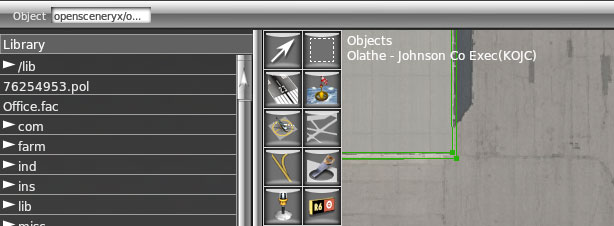
Figure 9: The current airport listed in the upper left of the map pane (in this case, KOJC/Olathe-Johnson County Executive)
Adding an Orthophoto Guide
When drawing runways, adding lighting, and so on (all discussed in the rest of this chapter), it may be helpful to have a real-world photo to guide you. To add orthophotos to your scenery (those real-world aerial photographs which overlay the terrain in X‑Plane, as used in scenery packages like those of RealScenery), you must first download some high quality orthophotos of the area.
For scenery in the US, it’s easy to obtain public domain orthophotos that may be used freely in our scenery; you can download them from the USGS Seamless Server. Outside the US, it may be more difficult-—copyrights on most imagery like this will prevent you from distributing the images with your scenery.
For help using the Seamless server, see the appendix Using the USGS Seamless Server.
From here on, we will assume that you have either downloaded orthophotos from the Seamless server, or that you have similar files from some other resource. The advantage to using the Seamless server is that you can download GeoTiff image files that have their geographic coordinates embedded in the files themselves.
Inserting and Tuning the Unmodified Images
The image files we downloaded from the USGS Seamless server are much too high resolution to use as-is in X‑Plane (at over 80 MB a piece, it would be far too RAM-intensive to load the whole thing when the simulator needed only a little slice). However, we can import our GeoTIFFs directly into WED in order to use them as guides (rather than as output files for X‑Plane). To do this, open the View menu and select the Pick Overlay Image… option.
Select the GeoTIFF files that you downloaded previously. Assuming the coordinate information in the files is correct, WED will automatically place the images where they should be.
Use the Marquee tool to select the newly inserted images, then give them a meaningful name in the hierarchy pane.
If your image did not include coordinate information, and you need to fine-tune the placement of your images, use the vertex tool to highlight the corners of you images. With a corner selected, you can use the Selection tab (in the bottom right of the window, when it is not hidden off the right side of the screen) to tune its latitude or longitude coordinates, along with its other properties. Alternatively, you could select your image’s corners and drag them to move them. This is, for obvious reasons, not nearly as accurate as putting in the exact coordinates that you want for the image.
With the image’s position perfected, you should be able to zoom in on your runways and see the X‑Plane runway aligned (nearly) perfectly with the runway in the photo.
You may want to group all your overlay orthophotos. To do so, select them all by holding down the Ctrl key (Windows) or Command key (Mac) and clicking the orthophotos in turn. Open the Edit menu and click Group.
Finally, to make sure that your overlay images don’t hide other parts of the runway, select the group containing all overlay images, open the Edit menu again, and select Move Last.
Adding and Modifying Runways or Sealanes
To add a runway, simply select the runway tool (numbered 2 in Figure 4), then click twice in the map pane to visually set the two endpoints of the runway. For the sake of consistency, click first on the northern or western end (depending on the runway’s orientation) and clicking second on the southern or eastern end. Note that for now, this does not have to be very precise—we’ll clean it up momentarily to make it pin-point accurate. (Note that sealanes are added identically to runways, but they use the sealane tool rather than the runway tool.)
After your second mouse click, the green drawing line will turn into an orange outline, and the runway will appear in the object hierarchy pane, with a long list of attributes below it.
After having placed the runway roughly where it belongs, use the Airnav database or another reference to manually specify the exact endpoints of the runway, as well as its other properties. With the runway selected (either because you just drew it or because you used the marquee tool and clicked on it), click the Selection tab (found among the editing tabs, described above). You should begin by setting the “Latitude 1” and “Longitude 1” attributes—these are the coordinates of the first end you drew previously, which should have been the northern or western end of the runway. Then, input the “Latitude 2” and “Longitude 2” coordinates. (Note that the Latitude/Longitude Center, Heading, and Length attributes will all be calculated automatically from these.)
Beyond these attributes, the order in which you input the data does not matter. At the very least, you should specify the runway width, the surface, and, of course, the name.
Some important attributes whose significance may not be obvious are:
- Roughness: this specifies how rough the runway is (and how much it bumps the plane around) when taxiing. This is on a scale from 0.0 to 1.0. A runway in good condition should have a roughness of about 0.25.
- Displaced Threshold 1 and 2: these specify how far from the end of the runway an aircraft is allowed to touch down, measured in feet or meters depending on your settings in the View menu. By default, the threshold is the end of the runway, so this is set to 0.0.
- Shoulder: this sets the surface type of the runway shoulder, which is a small section of pavement beyond the runway found mostly in large airports.
- Edge lights: runway edge lights are classified by the intensity of the light they produce. They can be High Intensity Runway Lights (HIRL), Medium Intensity Runway Lights (MIRL), or Low Intensity Runway Lights (LIRL), or the runway may have no edge lights at all.
- Markings 1 and 2: these specify the type of markings on each end of runway. Read more about these on Wikipedia.
- Blast pad 1 and 2: these specify the length (in either meters or feet) of the blast pad. A blast pad is an area of pavement at the end of the runway constructed to keep dirt and grass from being blown around in the jet blast created by a large aircraft taking off.
- Approach lights 1 and 2: many configurations exist for a runway’s Approach Lighting System (ALS). You can read about them on Wikipedia.
- REIL 1 and 2: the Runway End Identifier Lights.
- TDZ lights 1 and 2: the Touch Down Zone lights.
Having finished modifying a runway visually, you may want to lock it (as described in the section on The Hierarchy Pane above).
If a runway has been modeled using an OBJ or some other specific technique that replaces X‑Plane’s runway, a transparent surface can be selected from the drop down menu in the editing pane. This will allow users to get all of the menu items and approach lighting associated with a real runway, while still being able to set the surface physics and graphics themselves (using a draped polygon, with its physics specified in its .pol file).
Adding and Modifying Taxiways
The taxiway tool is used to draw taxiways and other pavement (including aprons, parking lots, and so on) using Bezier polygons. Before beginning, it is important to ensure that, when drawing these polygons, there is only one enclosed area per polygon—that is, make sure that the outline does not cross over itself at any point.
With this in mind, select the taxiway tool from the toolbar and create a rough outline of a section of pavement. At this point, you should not be making the shapes especially detailed—use a small number of nodes, with the intention of cleaning the shape up later. If at any point you need to delete/remove a single vertex, you can use the vertex tool to select that vertex and hit the delete key. The vertex will be deleted and a straight line will be drawn between the two remaining vertices on either side of the deleted vertex.
Perhaps the easiest way to handle the airport’s taxiways is to outline all the taxiways and other pavement in your object, then use the hole tool to cut out all the area that was selected which isn’t pavement. This will not work if you need markings on your (true) taxiways, though—in that case, you’ll need separate entities for each taxiway.
For instance, on the left in Figure 10, the taxiway has just been drawn—it covers a lot of area that it shouldn’t. Then, on the right, holes have been cut in it so that it doesn’t cover the grassy areas around it. It still isn’t pretty, but we’ll clean it up soon to more closely match the real taxiways.
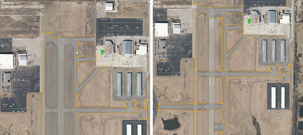
Figure 10: The rough outlined taxiways, before and after cutting holes in them (left and right, respectively)
Smoothing the Curves
Now that we have a very basic outline of our pavement drawn, we need to modify it to follow the contours of the actual airport’s curves. We’ll do this by turning the node near a corner into a curving node in the Bezier path, which will cause the line connected to it to curve around it. To convert a plain node to a curving one, hold down the Alt key and drag the mouse away from the point. After you let go of both the mouse and the Alt key, you can click and drag the outside arrows to further tune the curve.
You may need place an extra node between two points for the purpose of creating this curving node. To split the line connecting two points and place a node between them, highlight the points using the vertex tool, open the Edit menu, and click Split. Alternatively, you can highlight the points and press Ctrl+E in Windows, or Command+E on a Mac.
Repeat this process for each curve around the pavement.
For information on switching between the different types of nodes, see the chapter Bezier Path Tools.
Creating Markings, Signs and Lighting
Runway Lines and Markings
Now we will add markings to our runways, taxiways, and other pavement. Markings come in two varieties: perimeter markings (found around the outline of taxiways), and overlay markings (like taxilines, ILS, and hold short markings). The latter are essentially stand-alone lines, so they may also be useful for coping with complicated taxiway layouts
Note that whenever you select a tool that supports markings (e.g., the taxiway and taxiline tools), you can set that tool’s default markings (using the tool defaults bar at the top of the window). When you select a default marking in this pull-down menu, that marking will be applied to that tool until you change it. So if you were going to draw taxilines, you would select the taxiline tool, set the Markings drop-down to “Double Solid Yellow (Black),” then begin drawing the shape.
You can, however, draw the shape first and add the markings later. This is easily accomplished by selecting an entity (like a taxiway) with either the vertex tool or the marquee tool, then going to the attributes pane and setting the Line Attributes, Light Attributes, or both. When you do this, the markings will be applied to the entire shape. This is generally not what is desired, though, and you’ll need to remove the markings from some of the segments for taxiway intersections and the like.
To remove the markings from one section of the taxiway, select a single node using the vertex tool. Then, in the attributes pane, set its Line Attributes to none. The line connecting this node to whichever node was drawn after it will no longer have that attribute. For instance, if you selected Node 9 and set its Line Attributes to none, the line connecting it to Node 10 would have no markings.
Creating Runway Signs
To create a runway sign, select the sign tool from the toolbar. Click where you would like to place it, then drag your mouse around that point to orient it in the direction it needs to go. Note that the arrow coming out of the sign indicates its heading. To move a runway sign, use the marquee tool to click and drag it. To change its heading, drag it with the vertex tool.
For more information on these signs, and for examples of the text used, see the appendix on defining taxi signs or the X‑Plane/FlightGear Sign Specification page.
Creating Windsocks, Light Fixtures, and Airport Beacons
Windsocks, light fixtures, and airport beacons are all placed on the airport like runway signs (described above)—click to place them, and, in the case of the light fixtures, drag the cursor to change their orientation. You can use the marquee tool to change their position, and, in the case of light fixtures, you can use the vertex tool to change their heading.
Adding and Modifying Helipads
To create a helipad, simply select the helipad tool, then click and drag in the map pane to both set the pad’s location and its heading. After placing a helipad, you can set the helipad’s name, surface type, marking type, size, and so on using the attributes pane (either the selection tab or the helipads tab, depending on your preferred workflow).
Creating Airport Boundaries
Airport boundaries define the edges of the area considered an airport. These are used primarily when new global terrain is generated—they enable our scenery generation algorithms to flatten the appropriate airport terrain, and to apply appropriate land use textures. The elevation of the airport area is pre-processed to remove bumps and radar spikes (flattened), and the terrain type is set to airport grass.
Guidelines for drawing the airport boundary:
- The airport boundary should match a visual boundary between cleared airport area and surrounding terrain.
- The airport boundary should include any airport-related buildings, so that the elevation near terminals is well controlled.
- The airport boundary does not need to be very detailed—the boundary is slightly blended in the DSF file. Figure 11 shows a possible boundary for BWI. Note that the forest areas are probably on the property of the airport legally, but are not part of the airport boundary in the diagram so that the trees are not replaced with grass when the airport is built.
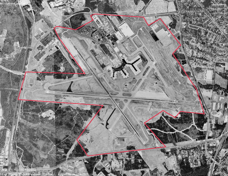
Figure 11: An example of determining an boundary
To draw an airport boundary, select the boundary tool and click at each corner around the airport. This is the area that will be flattened in X‑Plane when the rendering options are set to do so. When drawing the outline, be sure to go in one direction—either all clockwise or all counter-clockwise. When you have placed the last corner, press the Enter key to commit the points to the boundary. At this point, the boundary will appear in the object hierarchy pane; you can then name it there.
If your points aren’t in the places you would like, you can use the vertex tool to click the points and drag them.
Adding Objects and Auto-Generating Scenes
For the purpose of this tutorial, we will assume the objects to be used are already created and saved as .obj files, or composed into .agp scene files. You might use X‑Plane’s built-in objects, or any of the huge number of objects included in the OpenSceneryX package, all of which is available for free. If you download OpenSceneryX, be sure to select both the regular download and the Developer Pack.
With OpenSceneryX installed, it should appear in the library browser after restarting WED.
To add an object to your scenery, first find it in the library browser (the pane on the right side of the screen). Selecting an object there will also select the Object tool from the toolbar. Having selected the object, click in the map pane wherever the object should go, or right click and drag your mouse around to both place the object and set its heading. If you want to change the object’s heading after placing it, use the vertex tool, and if you want to move the object itself, use the marquee tool to drag it around.
For each object, you can choose at what object density (set in X‑Plane’s rendering options) that object will be visible. In the object’s “show with” field (visible in the attributes pane), you can choose to always have X‑Plane draw the object (by selecting “default”) or have X‑Plane only draw the object at the highest level of object density (by selecting “too many”), or somewhere in between.
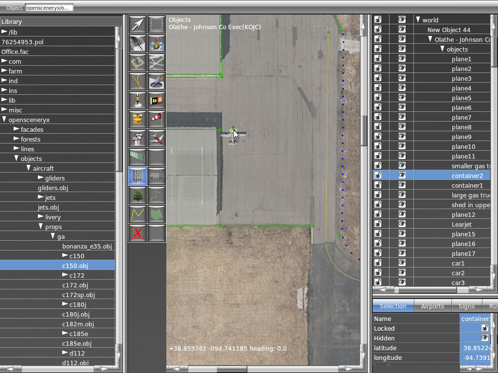
Figure 12: Adding an OpenSceneryX object to a scenery package
Note that in many cases, your drawn objects don’t have to match the objects in the orthophoto, due to the fact that X‑Plane will draw concrete pads where they would be in real life, and these pads will go on top of the orthophoto.
Drawing Object Strings and Line Markings
Object strings and line markings are drawn by default as open Bezier paths. To draw one, either select the object string tool or line tool, or select the resource you would like to draw from the library pane (possibly by typing str or lin in the library pane’s Filter box). Then, click in the map pane to place each vertex of the line. To change a string or line into a closed Bezier path (a ring), select the string in the hierarchy pane and check the box labeled “closed.”
Drawing Draped Polygons
To add a draped polygon (a surface that covers the X‑Plane terrain and takes its shape) to your scenery, first either select the polygon tool or find the resource you would like to use in the library pane (perhaps by typing pol in the library pane’s Filter). Then, click in the map pane to draw the polygon as a Bezier path.
Adding Facades
A facade in WED is essentially an image wrapped around a polygon at a specified height. This is used to build a simple building quickly and easily. Users specify only the shape of the building at its base, its height, and the .fac file to use.
To draw a building facade, select the facade tool from the toolbar (or select a .fac file from the library browser).
Use the facade tool to trace the outline of the scenery element you would like to draw. You can modify the points later using the vertex tool—remember that holding Alt and clicking on a point with the vertex tool will change it to a point of curvature in the Bezier path. After the facade is outlined, give it a name and change its height in the attribute pane as needed.
Drawing Forests
Overlay scenery created in WorldEditor can specify forested regions with a high degree of specificity. Using the forest tool, you can draw the outline of the forested region (using only plain nodes, with straight line segments). After a forest is drawn, you can set the following properties for it:
- Density, set as a ratio (where 0.0 is bare and 1.0 is full density),
- Resource, specifying what
.forfile will be used to fill the forseted region (and thus how the flora will appear in X‑Plane), and - Fill mode, specifying whether the forested region will be filled with flora (in “area” mode), lined with flora (in “linear” mode), or set only at the vertices you have drawn (in “point” mode).
Creating Airport Traffic Flow Information
An airport traffic flow defines a particular configuration of runways. Most large airports will have several “flows” depending on weather or time conditions, or type of aircraft, so WED allows you to create more than one flow as well.
An ATC traffic flow starts with an ATC flow item, which defines the flow’s name, its visibility/ceiling requirements, and its pattern runway. It can also specify the following rules:
- Zero or more runway uses, which define how various runways are to be used. Note that a runway can be used more than once, so a flow could have runway 4L for arrivals for turboprops as well as 4L for departures for props. If no runway uses are provided, X‑Plane’s artificial intelligence ATC will pick a runway.
- Zero or more time rules that define a set of times when the flow may be used. If no time rules are provided, the flow can be used at any time.
- Zero or more wind rules that define the wind limitations on the flow. If any wind rule meets the current weather, the flow can be used, so you can define a wide angle range at low wind speed and a narrow angle range at high wind speed.
To create a traffic flow, select your airport in the hierarchy pane, open the Airport menu, and click Create Airport Flow. Then, after selecting that flow in the hierarchy pane, open the Airport menu again and select Create Runway Use Rule, Create Runway Time Rule, or Create Runway Wind Rule. These rules specify under what conditions the runway should be used. X‑Plane will try to use the rules in order (from top to bottom), so be sure to order multiple flows from most specific to least. It also a good idea to have a generic, catch-all flow that can be used in all conditions in case the condiiton-specific flows overlook a possible scenario.
Note that the taxi routes (detailed below) generated by X‑Plane’s artificial intelligence are not part of the flow—-these routes do not change with flow.
For a step-by-step walkthrough of creating traffic flows, see the four part video tutorial on the X‑Plane YouTube channel.
Specifying ATC Taxi Networks
Taxi networks provide guidelines on how to get from one part of an airport to another. Every time X‑Plane starts it auto-generates taxi networks for airports, but these tend to have problems and are not very precise. Specifying a taxi network in World Editor will keep the AI controlled aircraft moving in a reasonable manner around an airport, instead of going through buildings or off the pavement. They also contain important data such as taxiway names and hold information.
To create taxiway routings for the AI aircraft, use the taxi routes tool and click to trace the path the aircraft should take. To do this efficiently, you may want to preset the properties of the taxi route tool using the tool defaults bar at the top of the window; then, you can draw all departure paths together, all paths for a specific runway together, and so on. If you do not set the properties that way, or need to change them later, you can select the taxiway(s) in the hierarchy pane, and then make your changes in the attributes pane below it. Note that there are additional fields in the attributes pane, such as latitude and longitude, that should not be edited.
The Departure, Arrival and ILS fields set up hold short parameters. The slop field indicates how close your point must be to another taxiway section in order to snap to it. Larger numbers allow the paths to snap together from farther away. The other preset fields are self-explanatory.
Check for degenerate edges, double nodes, and crossing edges before exporting an airport with a taxi network. These are found under the Select menu and will show any applicable errors in the attributes pane.
For additional tips and tricks, a five part video tutorial is also available on the X‑Plane YouTube channel.
Exporting the Scenery
When you have finished customizing the airport, open the File menu and select Validate. This command will check the WED file for errors based on the current export target. You can change the export target by selecting Target X‑Plane Version from under the File menu. Remember that selecting a version older than 10.0 might disable newer features, such as ATC data. If no errors are present, select Export Scenery Pack from the File menu. The new scenery will be visible the next time you load the area in X‑Plane.
All the files that the scenery package depends on are should be its folder (or referenced in the X‑Plane library, as would be the case when using OpenSceneryX objects). To share the scenery pack with a friend (or with the world via the Internet), just zip up your package folder (located in X‑Plane’s Custom Scenery folder). Instruct the other user(s) to unzip the folder into their Custom Scenery folder, after which the scenery will appear in X‑Plane on their computer as it does on yours. Beware, however, that external resources, such as scenery elements bundled with OpenSceneryX will not appear for other users unless they have those same resources installed. Thus, if you use OpenSceneryX in your scenery, be sure to tell your users to install it as well.
Airport Scenery Gateway
Alternatively, starting with WED 1.3, you also have the option to upload your files directly to the new Airport Scenery Gateway. This is a community-driven effort to collect airport data into a global airport database and will be a collection of all airport layouts authored by the X‑Plane community over the years. Submissions to the gateway are shared with all X‑Plane users as well as captured by Laminar Research periodically for inclusion in future releases of X‑Plane. Note: Third-party (such as OpenSceneryX) scenery elements are not compatible with the Scenery Gateway.
To upload a scenery package to the gateway:
Register for free as a new artist on the Gateway to establish your Gateway login credentials. 
Ensure that all buildings and other 3D objects are inside the folder in the WED hierarchy that represents the airport (just like runways must be).
Set the “Target X‑Plane Version” in the File menu to “Airport Scenery Gateway.”
Select File->Validate to run a validation pass on your airport. Any errors that would prevent Gateway upload will be located.
Select the airport you want to upload in the hierarchy. (Note that you can only upload one airport at a time.)
Select File > Export to Airport Scenery Gateway.
Input your username, password, and text description.
Click “Upload.”
To track your airport’s progress on the Gateway:
Log in to the Gateway. Artists must be logged in to see submissions until they have been accepted or approved by a moderator.
Click on the “Airport Scenery” menu option.
Search for your airport using the ICAO code.
Select the airport from the search results grid to view all submissions that exist for this airport.
Confirm that your submission currently has a status of “Uploaded.” This means the airport has been received by the Gateway but has not yet been acknowledged by the moderator. The moderator’s primary responsibility is to ensure the airport looks sensible, and no objects block the taxi routes, ramps, or runways. As multiple submissions appear for a given airport, the moderator will gradually raise the bar to determine the “Recommended” submission.
- Check back periodically to follow the progress of your airport submission on the Gateway. Airports may have the following status:
- Uploaded (Not yet acknowledged by the moderator.)
- Accepted (This airport submission has been acknowledged by the moderator, but not yet evaluated.)
- Approved (This airport submission has been approved as suitable for inclusion in a future release of X‑Plane. “Approved” submissions may be downloaded from the Gateway by X‑Plane users. However, if there are multiple approved submissions for the same airport, only the “Recommended” submission is a candidate to appear in a future release of X‑Plane.)
- Recommended (This airport submission has been recommended for inclusion in a future release of X‑Plane. Airport submissions that are “Recommended” at the moment of capture into the next release of X‑Plane will appear.)
- See Comments (This airport submission could not be approved by the moderator. The reason for this can be viewed by clicking the moderator comment button that applies to this submission.)
For more information, to register as an artist, or to download existing files, check out the Airport Scenery Gateway.
Editing Using the Map Tools
Tools used in WorldEditor can be categorized as follows:
- Selection Tools
- Marquee tool
- Vertex tool
- Entity Creation Tools
- Point Tools
- Directional Point Tools
- Helipad tool
- Taxi sign tool
- Light fixture tool
- Ramp start tool
- Object tool
- Non-Directional Point Tools
- Tower viewpoint tool
- Airport beacon tool
- Windsock tool
- Directional Point Tools
- Linear Tools
- Runway tool
- Sealane tool
- Exclusion tool
- Taxi routes tool
- Bezier Path Tools
- Taxiway tool
- Hole tool
- Taxiline tool
- Boundary tool
- Facade tool
- Forest tool
- String tool
- Line tool
- Polygon tool
- Point Tools
Selection Tools
When working with WED, you will be doing lots of selecting. There are two tools used for selecting entities, the vertex and marquee tools. Both of these tools can select entities by two means:
- By single-clicking on an entity, or
- By clicking and dragging a rectangle around an entity.
Selecting things with the marquee tool will result in a bounding box onscreen, which can then be manipulated (i.e., scaled), moved, and rotated using modifier keys in combination with cursor movements. For instance, holding down the Alt/Option key with some items selected with the marquee tool will allow you to scale and rotate the object. Selecting things with the vertex tool will allow you to edit entities on a point level—that is, you can move vertices and bezier handles.
There is some overlap in these tools depending on what you are selecting and what you want to do. For instance, you can use the vertex tool to select one end of a runway and move it, but you may also select that same end of a runway using the marquee tool. In a similar manner, you can select a single vertex of a taxiway with the marquee tool and move it, but not edit it’s shape via bezier handles (for that, you would have to use the vertex tool). A good rule of thumb is that you use the marquee tool to move, rotate, and scale selected items, and you use the vertex tool to manipulate individual points and entities.
Entity Creation Tools
With the exception of the selection tools, all tools in WED are used to create objects from points, lines, and bezier paths. With this in mind, we will consider the tools by type.
Point Tools
Directional Point Tools
Directional point tools include the following:
- Helipad tool
- Taxi sign tool
- Light fixture tool
- Ramp start tool
- Object tool
A directional point tool will allow you to place an entity and set its direction by clicking and dragging when placing the entity. If a single click with no dragging is used to place a directional entity, the entity will be placed with a heading of 0.00 degrees. The heading can be changed by either
- Selecting the entity and typing a numerical heading in the attributes pane, or 2.)
- Using the marquee or vertex tool to select and graphically rotate the entity by holding down the option key and clicking and dragging one of the corners of the bounding box.
Note that the helipad tool is not a “pure” point tool, as helipads can be resized and stretched. However, stretching a helipad to a non-square shape is not recommended, as it will result in a distorted texture in X‑Plane.
Non-Directional Point Tools
Non-directional point tools include the following:
- Tower viewpoint tool
- Airport beacon tool
- Windsock tool
Non-directional entites are simply placed by clicking in the map window where you want the entity to be. Each type of entity has its own set of unique attributes viewable and modifiable in the attributes pane.
Linear Tools
Linear tools include the following:
- Runway tool
- Sealane tool
- Exclusion tool
- Taxi route tool
A linear tool is defined by two endpoints, though the scenery entities created may later be scaled and rotated as though they were defined as a box. Placement of runways and sealanes can be accomplished with either
- two single mouse clicks, one for each end of the entity, or
- a single mouse click to establish one end and then clicking and dragging the second end graphically.
If you click and drag for the first point of a runway or sealane, a little crosshair cursor will appear which can then move around for exact placement of the first point. Releasing the mouse button will then allow you to click for the second point as usual.
Exclusion zones are drawn somewhat differently: simply click once and drag in a direction in order to draw an exclusion “box.” Use the vertex or marquee tools to fine-tune the size of this box.
You cannot click and drag with the taxi routes tool; you must click to place the first point, then click again each time to place the next segment. Press enter when the line is complete to stop adding points. To approximate curves with this tool, use multiple short segments. AI aircraft will automatically smooth any sharp angles or crudly drawn taxi routes in the simulator. Similarly to the Bezier path tools described below, a new point can be added to a taxi route by selecting the vertext tool, then Alt (Option on a Mac) clicking on the path.
Bezier Path Tools
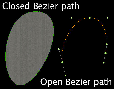
Figure 13: Open and closed bezier paths
Bezier path tools include the following:
- Taxiway tool
- Hole tool
- Taxiline tool
- Boundary tool
- Facade tool
- Forest tool
- String tool
- Line tool
- Polygon tool
Bezier tools are used to create freeform shapes. These shapes are commonly called Bezier curves or Bezier paths.
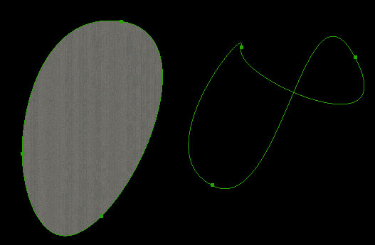
Figure 14: A normal Bezier path (filled, on the left) compared to a Bezier path crossing over itself (unfilled, on the right)
Drawing Bezier shapes may seem a bit foreign for the uninitiated, but with practice, it can become second-nature. There are some important concepts to know in order to successfully work with Bezier shapes. The first is that a Bezier shape may be open or closed. Figure 13 shows an example of open and closed Bezier paths. In WED, open Bezier paths are used only for the taxiline, taxi route, line, and string tools. Closed Bezier paths are used for the taxiway, hole, boundary, facade, forest, and polygon tools.
A closed bezier path is also called a “ring.” It is important to note that a closed Bezier path may not cross over on itself. Figure 14 shows two closed Bezier paths. You’ll notice that the path that crosses over itself has no fill (it is not solid), indicating a problem that will cause the entity not to render in X‑Plane.
Components of a Bezier Path
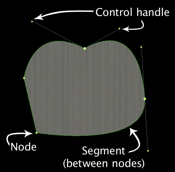
Figure 15: A node, segment, and control handles illustrated in a Bezier path
In order to learn to work with Bezier path, you need to know the pieces that make up a Bezier path. Figure 15 shows the primary parts of a Bezier path. The most fundamental part of the path is the node, represended as a round dot or triangle, depending on the node’s type. Attached to nodes are control handles, which are small triangles at the end of a line. A node can have 0, 1, or 2 control handles. The path between two nodes is called a segment. The location of two connected nodes’ control handles determines the shape of the segment between them. For instance, two nodes that each have no control handles will have a straight segment between them. All segments together compost the bezier path.
A node can have a few different configurations, as follows:
- Plain nodes have no control handles and are primarily used for sharp corners; the segments on both sides of a plain node will be straight. These nodes are represented by an upside-down triangle.
- Single-handle nodes have a control handle on one side of the node. The segment on one side of the node will be straight and the segment on the other side will be curved.
- Normal nodes have two control handles which are exactly opposite one another. Moving or extending one control handle causes the other to change correspondingly. This node is commonly used in the middle of a curve.
- Split (or “broken”) nodes have two control handles, but each handle can be moved or extended independently, thus changing the curve on either side of the node in different ways.
Creating Shapes
With the knowledge of the four node types, the next step is to string those nodes and control handles together in such a way as to create the shapes you want. A bezier path is created by selecting a Bezier tool clicking to outline your shape; a node will be added for each click (or click-and-drag) operation. A Bezier path may have as many nodes as needed to create the shape.
There are two ways to “complete” a shape (i.e., tell WED you are finished adding nodes)—either double-click when creating the final node, or change to another tool, in which case the last node you added will be the last point. Once the shape has been completed, you can edit it with the vertex tool.
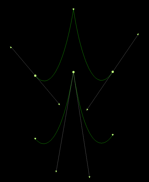
Figure 16: Different configurations of Bezier nodes resulting in the same shape
It is very common when drawing Bezier paths to work with all the node types. There is no one particular way to draw a path. Figure 16 illustrates that two similar shapes can be drawn with completely different types of nodes. With a little practice, you’ll soon get the feel for how you want to create your shapes.
When drawing curves, it is extremely common to convert between node types while in the middle of drawing a path. When in the process of drawing a path, you may only create plain nodes (by single-clicking) or normal nodes (by clicking and dragging). You must place either of these two types of nodes first, (optionally) convert them to a different node type, then continue drawing the path. Note that you cannot convert a node to a single-handle node while in the process of drawing the path. Once the path has been completed, however, you may convert between all types.
To convert from one type of node to another, use the modifier keys Shift, Ctrl (Command on Macs), and Alt keys in combination with single clicking or clicking and dragging. Figure 17 lists the keystroke combinations to convert between the node types.
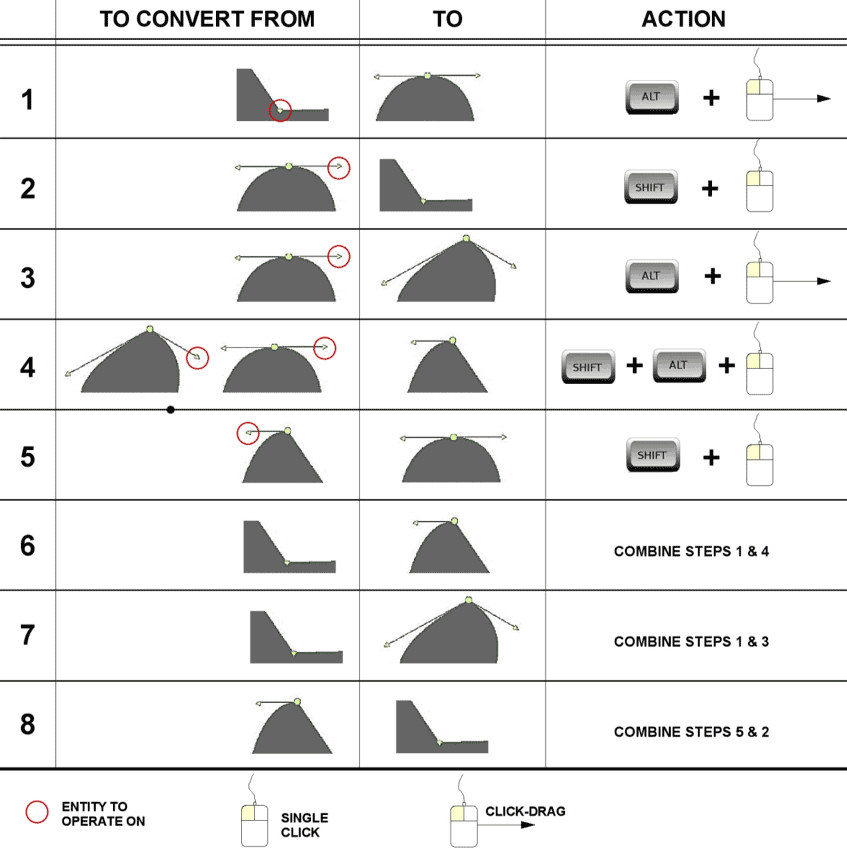
Figure 17: Chart for converting between Bezier node types in WED
Adding Nodes
Once a closed Bezier path has been drawn, you may want to add new nodes to the existing shape. To do this, use the vertex tool and select the two nodes on either side of the point where you would like to add a node. With the two nodes selected, open the Edit menu and click Split, or press Ctrl+E on Windows or Command+E on Macs. A new node will be created in the middle of the selected nodes.
Cutting Holes in Bezier Shapes
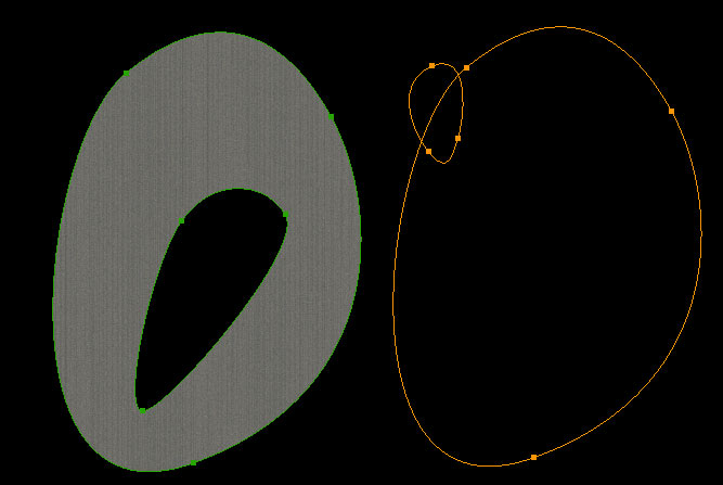
Figure 18: A comparison of a properly drawn hole (which is contained entirely within its parent shape) and an improperly drawn one (which crosses the boundary of its parent shape)
The hole tool is a Bezier type tool and is used to create holes inside of existing Bezier shapes. The most important thing to keep in mind when using the hole tool is that the Bezier hole must be entirely contained within its parent shape. Figure 18 show an example of this, where moving the hole outside of its parent entity will cause the shapes to lose their fill texture. A hole must be associated with another shape—this is done by selecting the parent shape (e.g., by using the marquee tool) before using the hole tool. You may select a shape using either the vertex tool or marquee tool. When the shape is outlined in orange, you may use the hole tool.
Since the hole is attached to a parent shape, moving the parent shape will move the hole also. However, you may select the hole with the marquee tool and move it withing its parent shape to relocate it, or select it with the vertex tool to reshape the hole.
Transforming and Rotating Shapes
After having created a shape, you can manipulate it: you can stretch it, scale it, or rotate it. To do so, use the marquee tool and select the entity. When you do so, a bounding box appears around the entity. By clicking and dragging one of the box’s nodes, you can stretch the shape. By holding down the Alt key, you can cause the bounding box’s nodes to become rotation nodes; by clicking and dragging a node, you can rotate the shape.
Texturing the Shape
Once a shape is created, you can specify what kind of surface the shape has. The shape’s texture has two properties: type and direction. The type of texture is specified in the attributes pane using the pull-down menu for the Surface property. Typical surfaces are asphalt, grass, dirt, water, and so on. The texture’s heading can be set using the Heading field in the attributes pane. To adjust the texture heading graphically, select the shape using the vertex tool, then hold down the Shift key and click and drag within the shape. As you drag the mouse, the texture will update in real time and you can align the texture as you like.
Advanced Topics
Synchronizing with Other Editors
In order to work with data from another program, you should do a one-time import of the files from that program, then work in WED only until you export your file for use in X‑Plane. You can export the scenery (by opening the File menu and clicking Export Scenery Pack) as many times as you like, but you must re-import files from other programs any time you modify them. Note that WED will not monitor your files for duplicates, so you might unintentionally import a copy of a file you already have (such as a DSF).
Note also that WorldEditor 1.2 will not automatically import projects from WED 1.1. You can, however, import your project manually.
Improving Performance of WorldEditor
If you have performance issues with WED, you can turn off the visual preview of objects. To do so, open the View menu and click Toggle Preview.
Recovering from a Crash
Starting with version 1.3, in the event that WED crashes, users can easily recover their work from a back up file that is automatically generated after every save. First, in the Custom Scenery folder, naviagate to the folder for the scenery that caused the crash. Inside the folder will be two .xml files: “earth.wed.bak.xml” and “earth.wed.xml.” Delete file “earth.wed.xml,” then rename the other file to “earth.wed.xml.” Upon restart, the scenery file will be restored to the last saved version from before the crash.
Menu Reference
The File Menu
| Menu item | Description |
|---|---|
| New Package | Creates a new package in the package list |
| Open Package | Opens the selected package for editing |
| Change X-System Folder | Changes which X-System folder WED is editing |
| Close | Closes the current scenery pack |
| Save | Saves the current sessions |
| Revert to Saved | Reloads the package from disk, going back to an old version. Note that you can undo a revert-to-saved. |
| Validate | Checks a scenery pack for errors and problems. |
| Target X‑Plane Version | Sets the oldest version of X‑Plane that can use the scenery pack. Note that older versions may not be able to use newer WED features. |
| Import apt.dat | Imports an apt.dat file. This brings up a list of airports in the apt.dat file to select from. Note that the default apt.dat is located in X‑Plane 10/Resources/default scenery/default apt dat/Earth nav data/. You will have the option of only importing some of the airports contained in the file. Hold Ctrl and click (Command+click on Macs) to select multiple airports, then hit the Import button. |
| Import DSF | Imports a DSF file from disk. |
| Import Orthophoto | Imports selected file from disk |
| Export apt.dat | Exports only apt.dat data into a single apt.dat file. |
| Export Scenery Pack | Exports the entire scenery pack, DSFs and apt.dats into your scenery pack, so you can fly it in X‑Plane. |
| Export to Airport Scenery Gateway | Automatically exports and uploads the selected scenery pack to the Gateway |
| Exit (Windows/Linux only) | Quits WED. |
The Edit Menu
| Menu item | Description |
|---|---|
| Undo, Redo | WED supports multiple levels of undo/redo for map items. Undo/redo is not available for text editing; instead, simply finish the text edit and then undo. |
| Cut, Copy, Paste | Only available for text editing. |
| Clear | Deletes the selection |
| Duplicate | Duplicates the selection. Note that this works for hierarchy items, so you can duplicate whole groups of items in the hierarchy pane. |
| Group, Ungroup | These group the selection in the hierarchy pane, or break apart any group that is selected. |
| Split | Introduces split points into any side of a polygon or line whose end-points are selected. |
| Merge | Merges two selected ATC network nodes into a single node, connecting the incoming routes of both. |
| Reverse | Reverses the winding direction of a polygon. Note that if a polygon is right-side out and is reversed, it will be inside-out and stop rendering. |
| Rotate | Rotates the order of sides on a polygon, which can change the position of facade sides and markings. |
| Crop Unselected | Deletes every unselected element from the WED project. Parents and children of the selected elements in the hierarchy are kept. |
| Move First, Move Up, Move Down, Move Last | Change the ordering of the selected object in the hierarchy pane (e.g., selecting move first will cause the selected element to be highest in whatever group it is in). |
The View Menu
| Menu item | Description |
|---|---|
| Zoom World | Zooms out to see the entire world. |
| Zoom Package | Zooms to show only the contents of the currently open package. |
| Zoom Selection | Zooms in to see the selected items filling the map pane. |
| Feet/Meters | Changes the height/length units in the property editor. |
| Show Line Markings | Shows a simple color preview of taxiway and line markings for apt.dat files. |
| Show Vertices | Shows each vertex as a small dot. |
| Pavement Transparency | Selects a level of transparency for all apt.dat pavement. |
| Object Density | Shows a preview of the objects that a user would see at a given object density (set in the Rendering Options window in X‑Plane). |
| Pick Overlay Image | Creates a new overlay image from disk for reference purposes. |
| Toggle World Map | Turns the low-resolution background world map on or off. When checked, the background map is enabled. |
| Toggle Preview | Toggles semi-realistic preview of objects, AGPs, pavement, and .pol files. When checked, these previews are enabled. |
| Restore Frames | Resets the frames of the WED editing window to their default position. |
Select Menu
| Menu item | Description |
|---|---|
| Select All, Select None | Select every object in the package or none of them. |
| Select Parent/Select Children | Select the parent or children of the current selection in the hierarchy. |
| Select Polygon | Given a selected vertex, selects the polygon that contains it. |
| Select Vertices | Given a selected polygon, selects its vertices. |
| Select Degenerate Edges | Selects ATC edges of zero length (i.e., edges between two points that are on top of one another). These are good edges to delete. |
| Select Double Nodes | Selects any ATC nodes that overlap each other. These are good nodes to merge. |
| Select Crossing Edges | Selects ATC edges that cross each other. These edges should be split. |
| Select Local Objects/Library Objects/Laminar Library Objects/Third Party Library Objects/Missing Objects | Selects objects meeting the criteria |
Airport Menu
| Menu item | Description |
|---|---|
| Create Airport | Creates a new airport within the package. |
| Create ATC frequency | Creates a new ATC frequency for the current airport. |
| Create Airport Flow | Creates a new, empty airport flow for the current airport. |
| Create Runway Use | Adds a runway use rule to the selected flow. |
| Create Runway Time Rule | Adds a new time rule limitation to the current flow. |
| Create Runway Wind Rule | Adds a new wind rule limitation to the current flow. |
| Edit Airport [airport] | Changes the current airport to the selected one. |
Property Reference
The following is a list of object types with descriptions of the properties associated with them. Note that all objects have an additional Name property, which generally simply identifies them in the hierarchy.
| Property name | Description |
|---|---|
| Airport Beacon | |
| Type | The type of airport beacon at this airport. |
| Airport Boundary | |
| Lines | The pavement line markings attached to this boundary, set on a per-point basis. |
| Lights | The lights attached to this boundary, set on a per-point basis. |
| Airport Lines | |
| Lines | The pavement line markings attached to this line, which may be set either at the level of a line or its points. |
| Lights | The airport lights attached to this line, which may be set either at the level of a line or its points. |
| Airport Sign | |
| Style | Currently only “default” is supported. |
| Height | Height of the sign, defined as one of several preset sizes. |
| Name | Interpreted as a sign code for these entities. See the apt.dat 850 or 1000 file specification for the meaning of the sign codes, or see the appendix on defining taxi signs for more help. |
| ATC Flow (X‑Plane 10 only) | |
| ICAO | The METAR ICAO code of the airport whose weather determines the use of this flow. For smaller airports, their flow may be dictated by a nearer larger airport, so this ICAO may not be the ICAO of the airport that contains the flow! |
| Minimum ceiling | The minimum ceiling in feet/meters at which this flow can be used. |
| Minimum visibility | The minimum visibility in sm at which this flow can be used. |
| Pattern direction | Defines whether the airport uses left or right traffic. |
| Pattern runway | The runway to be used for pattern operations. |
| ATC Frequency | |
| Type | The type of frequency (e.g. ground, delivery, etc.) |
| Frequency | The actual frequency, in MHz. |
| ATC Runway Use (X‑Plane 10 only) | |
| Runway | The runway to use |
| Traffic type | A set of aircraft categories (e.g., prop, jet) that can operate on the runway. |
| Operations | The type of operation (e.g. departure, landing) that can operate on the runway. |
| Departure heading min/max | Defines the range of headings ATC can give the aircraft on takeoff from this runway. |
| Initial heading min/max | This defines the range of headings that the first waypoint for the departure can still be in to receive this runway. |
| ATC Time Rule (X‑Plane 10 only) | |
| Start time | The earliest time this flow can be used, in Greenwich mean time (GMT), or Zulu time. |
| End time | The latest time this flow can be used, in Greenwich mean time (GMT), or Zulu time. |
| ATC Wind Rule (X‑Plane 10 only) | |
| ICAO | The ICAO of the airport whose wind is being measured. Like ceilings, the airport whose weather determines flow may not be the same as the airport you are currently working with; small airports must often do what big airports dictate. |
Draped Orthophoto .pol |
|
| Heading low/high | The range of wind direction for which this rule is in effect |
| Speed (knots) | The maximum wind speed for which this rule is in effect |
| Resource | The file name of the .pol file that defines the texture for the draped orthophoto |
| Exclusion Zone | |
| Exclusion flags | These define what types of 3-D entities are excluded below this rectangle. The OBJ exclusion excludes objects and autogenerated X‑Plane 10 elements. |
| Facade | |
| Resource | The file name of the .fac file that defines the look of this facade. |
| Show level | The minimum rendering settings at which this object is guaranteed to appear. By picking higher rendering settings in this popup, you allow X‑Plane to drop your facade when the user’s rendering settings are low. If you pick a low rendering setting, your facade will always appear. |
| Pick walls | Check this box to define the wall types on a per-node basis (available in X‑Plane 10 only). |
| Forest Placement | |
| Resource | The name of the .for file that defines the look of this forest. |
| Density | The vegetation density in this forest stand as a ratio, where 0.0 is none and 1.0 is maximum density. |
| Fill mode | Defines whether the forest has trees filling the area, around the edges, or just at corners |
| Helipad | |
| Surface | The appearance of the surface of the pad, such as concrete or asphalt. |
| Markings | Markings on the helipad itself. |
| Shoulder | The type of shoulder around the helipad. |
| Roughness | A ratio of roughness, currently ignored by X‑Plane. |
| Edge lights | The type of lights around the edge of the pad. |
| Light Fixture | |
| Type | The type of lighting fixture. Non-operational fixtures like apron lights can be placed as library elements. |
| Angle | The glide slope that shows correct descent for PAPIs and VASIs. |
| Line Placement | |
| Resource | The path to the .lin file that defines the look of this line. |
| Closed | When checked, WED will automatically close the line to make a loop. |
| Object Placement | |
| Resource | The path to the .obj or .agp file that defines the look of this object placement. |
| Show level | The minimum rendering settings at which this object is guaranteed to appear. By picking higher rendering settings in this popup, you allow X‑Plane to not display your object when the user’s rendering settings are low. If you pick a low rendering setting, your facade will always appear. |
| Has custom MSL height | Check this to specify the vertical position of the object explicitly (available in X‑Plane 10 only). |
| MSL height | When “Has Custom MSL Height” is checked, this is the height above mean sea level at which the reference point of the object is located (available in X‑Plane 10 only). |
| Polygon Placement | |
| Resource | The path to the .pol file that defines the look of this draped polygon. |
| Heading | The heading, in degrees, to which the draped polygon’s texture is rotated. |
| Ramp Position | |
| Ramp type | The type of parking spot (available in X‑Plane 10 only). |
| Equipment | Selects all airplane classes that can legally park at this spot (available in X‑Plane 10 only). |
| Runway | |
| Surface | The material the runway itself is built out of. |
| Shoulder | The material the shoulder of the runway is built out of, if there is one. |
| Roughness | A ratio for how bumpy the runway is (currently ignored by X‑Plane). |
| Center lights | A check box to enable centerline lights on the runway. |
| Edge lights | The type of edge lights. Note that X‑Plane does not vary brightness between MIRL, HIRL and LIRL. |
| Distance signs | Check this box to have X‑Plane generate distance remaining signs every 1000 feet. |
| Displaced threshold (at each end) | The number of meters to displace the landing theshhold from the end of the runway. |
| Blast pad (at each end) | The number of meters of blast pad next to the runway. |
| Markings (at each end) | The touch down markings for this end of the runway. |
| Approach lights (at each end) | The type of approach lights for this end of the runway. |
| TDZ lights (at each end) | Check this to enable touch down zone lights on this end of the runway. |
| REIL lights (at each end) | The type of runway end identifier lights—pick unidirectional, omnidirectional, or none. |
| Sealane | |
| Buoys | Check this to have X‑Plane generate buoys along the sealane. |
| String Placement | |
| Resource | The path to the .str file that defines the look of this object string. |
| Spacing | The distance between object placements in meters. |
| Closed | Check this to make a closed loop rather than an open line. |
| Taxi Route | |
| One way | Check this if traffic on this route should only flow in one direction. Be careful with this property, as it puts pressure on ATC to make circuitous routes. |
| Runway | Check this if the ATC taxi route is on a runway. |
| Departures | A set of all runways that this route intersects with for the purpose of departures. This can include an intersection between the route and the airspace after the departure end of the runway. |
| Arrivals | A set of all runways that this route intersects with for the purpose of arrivals. This can include an intersection of the route with the airspace before the touchdown zone or after the departure end. |
| ILS precision area | A set of all runways whose ILS precision areas intersects this route. |
| Taxiway | |
| Surface | The material that makes up the surface of this taxiway. |
| Roughness | A ratio for how bumpy the runway is (currently ignored by X‑Plane). |
| Heading | The direction of the “grain” of the surface, in true degrees. |
| Lines | The pavement line markings attached to this line—may be set on the line itself or on its points. |
| Lights | The airport lights attached to this line—may be set on the line itself or on its points. |
| Tower Viewpoint | |
| Height | The viewpoint’s height above the ground when using the tower view in X‑Plane. Note that this simply controls where the camera is placed in tower view mode—it does not create a control tower. Place a control tower object using a library object. |
| Windsock | |
| Lit | Check this to make the windsock be lit at night. |
Appendix: Anatomy of the X‑Plane Scenery System
This is a broad overview of the architecture of X‑Plane’s scenery system. It provides a road map for authors on how the various components fit together.
Scenery Packages
In X‑Plane, all scenery content comes in a scenery package. A scenery package is a folder with a predefined file organization.
Custom scenery is typically distributed as a single scenery package. A scenery package can contain art assets for the library, tiles, airport data, or any combination of the above.
Scenery packages are installed in the “Custom Scenery” folder. Scenery packages have a priority order, defined by their file name alphabetically; X‑Plane also stores the default “global scenery” in packages (stored in the Global Scenery folder) and the sim’s built-in art assets are stored in packages in Resources/default scenery/. All third party scenery should be packaged and installed in the “Custom Scenery” folder.
See the Scenery Package Organization article on the X‑Plane Wiki for further reading on package files, or see the “Expanding X‑Plane” section of the X‑Plane 10 manual for information on how to download and install a custom scenery package.
Components of a Scenery Package
A scenery package is simply a folder that contains scenery. Within that package may be many files, including:
- Art assets, which are textures, meshes, or other definitions used to visualize scenery.
- Tiles, which define what sorts of things are on a small portion of the Earth.
- A library file, which forms a “master list” of all art assets for use in all scenery packages.
- An airport data file, which defines the layout of one or more airports.
Scenery Tiles (DSF)
X‑Plane divides the planet into thousands of 1x1 degree “tiles,” which are “cut” along latitude and longitude lines. For a given area of the earth, tile files are loaded to build the local contents of the planet. There are two kinds of tiles: base mesh and overlay.
X‑Plane normally maps a 3x2 tile region (3 east-west, 2 north-south) to provide about 200x200 km of loaded scenery at any one time.
There are two kinds of tile formats: DSF (distribution scenery format) is the current tile format, supported in X‑Plane 8, 9, and 10. ENV (environment file) is the legacy tile format supported in X‑Plane 6 and 7 (and supported but deprecated in versions 8 and 9). The rest of this article will refer only to DSFs. Any new scenery you create should use DSFs.
Tiles are named by the latitude and longitude of their southwest corner. They live in a folder that defines a 10x10 block of tiles, defined by its southwest corner, and that folder in turn lives in a per-planet folder, which lives in your custom scenery package. For example, consider the following hierarchy:
- X‑Plane Install/
- Custom Scenery/
- My Awesome Boston Scenery/
- Earth nav data/
- +40–080/
- +42–071.dsf
- +42–072.dsf
- +40–080/
- Earth nav data/
- My Awesome Boston Scenery/
- Custom Scenery/
“My Awesome Boston Scenery” is the name of the package. Note that there can be no sub-folders introduced in this particular layout—layout of DSF tiles is fixed.
DSFs are binary files. As such, they contain the coordinate and location data for a tile but not the art assets. For example, in an orthophoto scenery package—that is, scenery where the ground texture is taken from a real photo—the shape of the mesh (the elevations) will be in the DSF, but the image of the orthophoto will be in separate art asset files.
Tile files can contain:
- Base mesh triangles (base mesh tiles only).
- Beach placements, defined by 3-d polygonal outlines of the land-water polygon (base mesh tiles only).
- Road grids, defined as a connected set of line segments with road type information.
- Model placements, defined as points and rotations.
- Facades (that is, buildings extruded from a footprint), defined as a polygonal footprint + height.
- Forests of trees, defined as a polygonal footprint + density information.
- Draped polygons, defined by polygon, for overlaying orthophotos or other repeating textures, like pavement.
- Draped painted lines, defined by a polygon path, typically used for custom taxiway lines, etc.
- Strings of objects, defined by a path, often used for adding a series of runway lights.
In all cases, the DSF file contains the coordinate location information and a reference to an art asset file that is stored separately.
Base Mesh Tiles
For any given tile, only one tile file can provide the base mesh, or ground. The base mesh is a textured triangle mesh used to model mountains, water, land, etc. Base mesh tiles can also contain all of the components of overlay files if desired.
For further reading, see the DSF File Specification and DSF Usage by X‑Plane articles on the X‑Plane Developer Site.
Overlay Tiles
A tile file can be marked as an overlay—in this case, its contents are superimposed over other tile files. Overlay files cannot contain any base mesh information. An overlay file is often used to add additional details. For example, an overlay tile could add the buildings of an airport.
Overlay tiles are loaded in priority order. An overlay can contain “exclusion zones,” which are lat-lon rectangles that prevent elements of lower-priority tiles from being loaded. For example, if an overlay tile contained placements for custom buildings for Manhattan, the author would also create an exclusion zone around Manhattan that would prevent the default buildings (that ship with X‑Plane) from appearing there.
For further reading, see the About Overlays article on the X‑Plane Wiki.
Art Assets and the Library
All art assets are stored in scenery packages, but never directly inside a DSF. Typically an art asset is built from a combination of text files and image files. X‑Plane supports DDS, PNG, and BMP; BMP is not recommended. DDS is the preferred format for scenery use. The text files often contain information on how to use the texture and other useful properties. For example, the “.net” file format, which defines a road network, indicates the shape of roads to be built, the physical properties of the roads (e.g., how bumpy they are), how to map the texture to the roads, and where to place cars on those roads.
A quick cheat sheet to art asset file types:
.ter– A terrain definition; the file lists physical properties, scaling information, and texture files..obj– OBJect—that is, a 3-d model/mesh. This is not the same format as an Alias/Wavefront OBJ files..fac– Facade definition; the file describes how to extrude a building from a footprint using a texture..for– Forest definition; the file describes how to build trees from a texture for placement within a polyogn..bch– Beach definition; the file describes how to tile a beach from a texture..net– Road network definition; the file describes how to build 3-d roads and place traffic for several road types from several textures..pol– Draped polygon; describes how to texture a polygon that is “draped” over the existing mesh using a texture..str– Object string; describes how to place a number of OBJ files along a line..lin– Line; describes how to paint a line along the mesh.
Note that .pol (draped polygons) can be used in an overlay, while .ter (base mesh terrain) can only be used in base meshes. Base mesh performance is significantly faster than draped polygons; draped polygons should only be used to customize small areas of the world, like an airport surface area. These files are not appropriate for large-scale orthophoto scenery!
Art asset “primary” files (e.g. OBJ, FAC, etc) can be in any location within a scenery package—they are defined by relative paths. So you can organize your art assets as desired. The dependent (“secondary”) files like DDS textures should be in the same folder as the art asset. An example:
- X‑Plane Install/
- Custom Scenery/
- My Awesome Boston Scenery/
- Earth nav data/
- +40–080/
- +42–071.dsf (references kbos/hangar.obj)
- +42–072.dsf (references bos/fenway.obj)
- kbos
- hangar.obj (references hangar.dds)
- hangar.dds
- bos
- fenway.obj (references fenway.dds)
- fenway.dds
- +40–080/
- Earth nav data/
- My Awesome Boston Scenery/
- Custom Scenery/
In this layout, the .obj files can be moved anywhere within My Awesome Boston Scenery as long as the relative paths in the DSF are adjusted.
Objects
OBJ files are the main way to get 3-d models into X‑Plane. They are used for both scenery models (e.g. buildings) and the 3-d visualization of airplanes. An OBJ is a text file, but typically they are edited using a 3-d editor like AC3D or Blender and exported. Objects can be animated, and have a number of specialized features that can be used only in airplanes.
For further reading, see the OBJ Overview on the X‑Plane Wiki, or the OBJ8 Specification article on the X‑Plane Developer site.
Polygons
The polygon definitions in a DSF can sometimes have holes and sometimes they can be bezier curves; what is allowed depends on the art asset type. For example, bezier curves are allowed for draped polygons but not facades; holes are allowed for forests but not facades.
For further reading, see the DSF Usage by X‑Plane article.
Road Networks
Road networks may be specified in overlay files, but they require MSL elevation (that is, their altitude is predefined). The lack of on-the-fly elevation adjustment for overlay road networks is a problem for making add-on road packs; fixing this limitation is an area of ongoing development.
For further reading, see the NET File Specification article on the X‑Plane Wiki.
Library
The library provides a way to locate art assets by a virtual file system, rather than by the physical file system. The library allows one scenery package to “publish” an art asset (by providing it with a virtual file name in the library) and another scenery pack to use that art asset (by referring to it by its virtual file path).
The library system is useful for a few reasons:
- It hides the actual layout of art assets from third parties, breaking a dependency. Laminar Research can (and does) rebuild our art assets periodically; this does not affect third parties because we map our assets to the legacy virtual paths.
- It allows scenery packages to share art resources independently.
- It allows scenery packages to augment or replace or customize the art assets that ship with X‑Plane.
- It allows a many-to-many relationship between art assets and usage. For example, we map many car .obj files to one virtual path, allowing for a variety of traffic. We map a particular building to both legacy and current virtual paths, so that we can provide legacy art asset support without having to duplicate the files on disk.
Note that image files are not shared via the library system; instead the text file that references them is shared.
Art assets do not have to be placed into the library system—a package can simply access them by relative file paths. Or, a package can put its art assets into the library and then reference them by virtual path, allowing for customization by other packages.
Art assets are placed in the library by putting a file called “library.txt” into the root of your package, like this:
- X‑Plane Install/
- Custom Scenery/
- My Awesome Buildings/
- library.txt (maps houses/house1.obj to lib/g8/buildings/60_30.obj and houses/house2.obj to lib/g8/buildings/60_30.obj)
- houses
- house1.obj (references house.dds)
- house2.obj (references house.dds)
- house.dds
- My Awesome Buildings/
- Custom Scenery/
Note that in this case, another scenery package that references houses/house1.obj will not use these files. That is because scenery packages can only use each other’s art assets via virtual path. A scenery pack that references “lib/g8/buildings/60_30.obj” (a virtual path) might end up with either house1.obj or house2.obj.
Library files let you specify the replacement semantics for art assets–that is, a library file can provide additional variants of an art asset or replace the art asset completely. Libraries can specify what tiles (in latitude/longitude) can use the art asset for ‘regionalization’.
For further reading, see the articles Airport Customization Tutorial, Using the Library System, The X‑Plane Library System, Library File Format Specification, and Tutorial on Customizing X‑Plane’s Default Scenery Artwork on the X‑Plane Wiki.
Airport Data
The data that describes the layout of an airport are stored in apt.dat files. Robin Peel maintains the file format and the master database of airports that form the “default” scenery for X‑Plane.
There is one apt.dat file per package per planet, like this:
- X‑Plane Install/
- Custom Scenery/
- My Awesome Boston Scenery/
- Earth nav data/
- apt.dat
- Earth nav data/
- My Awesome Boston Scenery/
- Custom Scenery/
The apt.dat file can contain one or more airports; each one fully replaces the previous airport’s definition. (That is, you cannot simply add a runway to the existing KBOS, you must fully re-specify KBOS).
You do not need to provide tiles for the airports you cover, or vice versa.
Airport data does not affect the terrain type below the airport; airports in the default scenery that X‑Plane ships have grass underneath them because the base mesh creation process added the grass. If you add a new airport, you may need to include an overlay tile with .pol placements that drape new terrain over the old; X‑Plane’s art assets for airport grass are all exported into the library for this purpose.
For further reading, see Robin Peel’s X‑Plane Airport & Navigation Data home page.
Airport vs. DSF Overlays
Airport definitions do not use any specific art assets; the file format models airport data and lets X‑Plane use built-in art assets to draw.
However, all of the types of drawing that are possible in an airport (pavement, lines, lights) can be created using DSF overlay data. The intention is for authors who want to truly customize the look of their airport to use DSF overlays.
.polfiles have the same functionality as taxiway and runway pavement..linfiles have the same functionality as taxiway lines..strfiles have the same functionality as taxiway lights..objfiles are actually used to build the lights that are placed in an airport–each runway light is actually an OBJ!
Some of X‑Plane’s art assets for airports are available via the library.
For further reading, see the Advanced Airport Customization article on the X‑Plane Wiki.
Types of Custom Scenery
Here are some examples of scenery add-ons:
- A customized airport. The package contains OBJs for the various buildings, an apt.dat file with a new layout, and an overlay DSF placing the objects.
- A new base mesh. The package contains a base mesh DSF and .ter files for the orthophotos. Because of the amount of data required to create a base mesh, this is for advanced scenery authors only.
- Regionalized Buildings. The package contains only OBJ files for customized buildings and a library.txt file to place them in the library.
Appendix: About the X‑Plane Library System
Since Version 8, X‑Plane has employed a library system to locate the bitmaps, models, and other graphic resources it depends on. You can use the library system to replace virtually any part of the artwork for the global scenery.
Libraries and Scenery Packages
Any X‑Plane scenery package can be a library. To be a library, a scenery package must have a text file called library.txt directly inside it. This text file contains a list of all of the resources the library shares with X‑Plane.
X‑Plane scenery packages can be in either the Custom Scenery folder or the Default Scenery folder. The Custom Scenery folder is for add-on scenery packages that are installed by the user; the Default Scenery folder is for the scenery packages that come from Laminar Research and are installed with the simulator.
Note: The X‑Plane updater/installer will sometimes upgrade the default scenery packages that come with the sim. It will not alter custom scenery packages. For this reason, all add-ons should be placed in the Custom Scenery folder!
The library.txt file maps a file path for a resource inside the package to a virtual path that scenery can use. File paths are the actual locations of the objects on disk. Virtual paths are used by the DSFs that need artwork.
How X‑Plane Locates Objects, Terrain, and other Graphic Resources
As X‑Plane loads scenery, it must locate each object, terrain definition, etc. First X‑Plane looks in each scenery package, in alphabetical order, first in custom scenery, then in the default scenery folder. If X‑Plane finds a virtual path in a library.txt file in a package, it uses the object or terrain in that package located by the file path that is associated with it.
If X‑Plane cannot find the object as a virtual path in any library, it then looks in the scenery package the DSF is located in for an actual file. A few things to note about this:
- X‑Plane will only look in a scenery package other than the one a DSF lives in for files in the library.txt. It does not actually look at the files in the package, only the library.txt file. So if you do not include a library.txt file, no other package will use your objects/terrains, etc.
- X‑Plane matches virtual paths, not real file paths, when looking up files in the library. This means you can name your customized artwork anything you want—you only need to match virtual paths.
- Because you can map any virtual path to any file path in your library.txt file, you can use one object or terrain for many virtual path entries without having to duplicate the actual files.
- You can also map one virtual path to multiple file paths. For objects, X‑Plane will randomly pick one of the objects, to provide more variation.
Customizing Objects
You can customize the objects used in the global scenery. The virtual paths for the objects in the global scenery are named by their size and the terrain they are used with. The size can be thought of as a maximum limit as you make objects; this is how much space the scenery-creation tools reserved for each object.
There are two separate sets of objects for the global scenery—one for the US and one for the rest of the world. Because the US has much higher road density, the US objects are all relatively small. World objects are much larger.
The global scenery objects are not meant to be one building each. For example, a 200x30 meter object in the US can be 7 houses next to each other, a shopping mall with a parking lot, or one large building.
Customizing Terrain Textures
You can customize the terrain textures used in X‑Plane. This is done by providing new “terrain info” (.ter) files. If you do not provide .ter files, X‑Plane will not use your textures. X‑Plane loads your .ter files and from there will pick a PNG in your package. If you override a .ter file, you must provide all of the textures for that .ter file in your package.
Night lighting is not automatic for scenery; you must provide a TEXTURE_LIT line in your .ter file to enable night lighting. The lit texture may have any name; we recommend using the _LIT suffix for clarity, but any name will work.
Someday X‑Plane may feature seasonal textures; when this happens, the TEXTURE_LIT command will allow one .ter with multiple daytime seasonal textures to share a single night lighting map.
Customizing Roads
X‑Plane uses exactly one road definition (a .net file) for all roads in a given DSF. One .net file may define many road types, so subtypes within the road file are used to create variety. This means you must include all of the textures and objects for your entire set of roads.
Customizing Beaches
All default beaches in X‑Plane exist in one image file and are referenced via one .bch file. So you must provide all beach definitions if you are going to provide any. Only one beach definition (a .bch file) may be used per DSF. Subtypes within the beach are used to create variety.
Appendix: Using the USGS Seamless Server
This section describes how to use the United States Geological Survey’s server to download orthophotos for use in airport scenery. This data is available for the US only.
To begin, go to http://viewer.nationalmap.gov/viewer/, as seen in Figure 19.
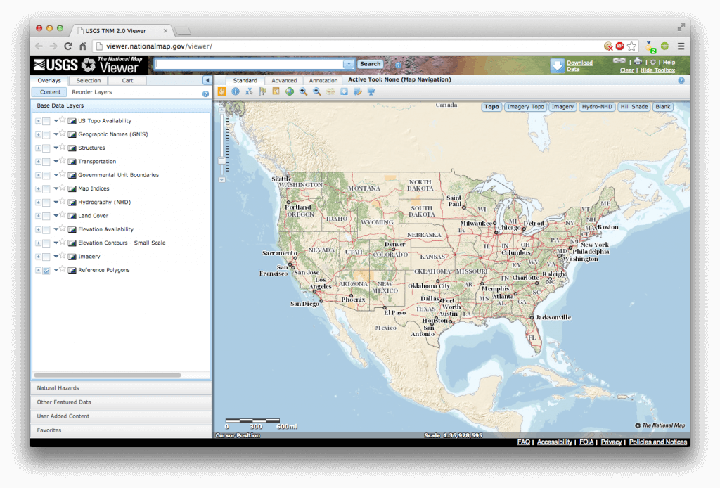
Figure 19: The USGS National Viewer Start Page
In the search bar at the top of the page, search for your desired location, as seen in Figure 20.
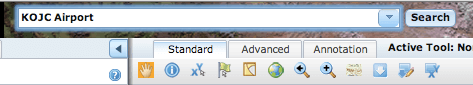
Figure 20: Searching for our example airport (“KOJC Airport”).
After searching, you should see your airport in the viewing area. To make this easier, be sure to select the “Imagery” view option in the upper right hand corner of the viewing area, as shown in Figure 21.
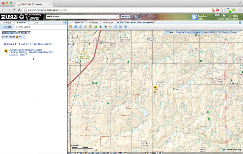
Figure 21: Selecting the Imagery viewing style
After zooming a bit and using the map navigation tool (the hand in your toolbar) you should be able to see your airport. Our example airport, KOJC, is clearly visible in Figure 22.
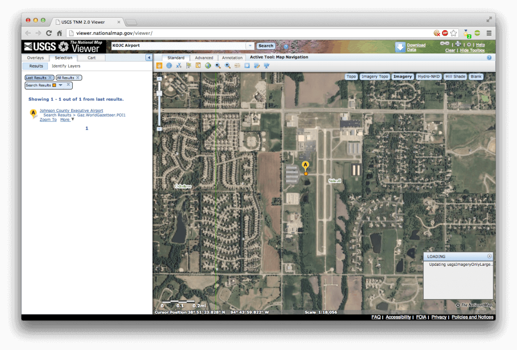
Figure 22: Zoomed to the KOJC airport
Select the “Download Data” button from the top-right portion of the page, as shown in Figure 23.
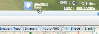
Figure 23: Selecting the Download Data tool
From here you will see a small window pop up with your download option. Click on the first option to “draw and download by bounding box.”, then click and drag to select the whole of your airport, as in Figure 24. It’s better to err on the side of downloading too much than downloading too little.
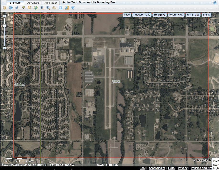
Figure 24: Selecting the download area
After selecting your download area, you will see a new box pop up with the options for available data to download, as shown in Figure 25. Be sure to check “orthoimagery” along with any other data you wish to download.
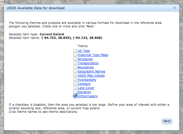
Figure 25: Selecting your desired data
Click next, and in the new window, select the source of your data, as shown in Figure 26. Here we’ve selected third option. Though better resolution does exist, we selected this for its file type - it’s a GeoTIFF file - and it has the most recent date. GeoTIFFs are image files that have their geographic coordinates embedded in the files themselves.
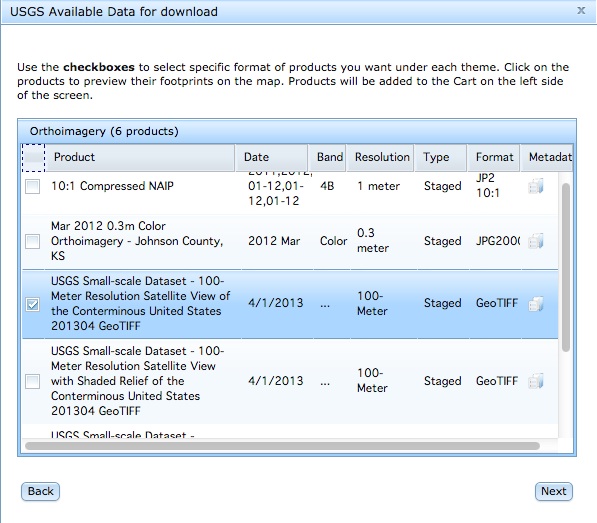
Figure 26: Selecting your data source
After selecting next, you will be taken to your “cart” on the left of the viewing area (don’t worry - it’s free). You can download your file immediately from the Preview box located just below the Selected Items box. You can also download the files by selecting “checkout,” where you will be prompted for your email address. It took us less than 10 minutes to receive the email - it will contain links to download the data you selected as .zip files. Depending on the size of the data area, it may be broken into multiple links to ease the downloading time for each file.
Appendix: Defining Taxi Signs
After laying out a series of taxiways and aprons and providing them with markings, an airport layout can be completed by providing taxi signs which identify the different taxiways and runways as well as provide directions and warnings for pilots.
Creating a taxi sign in WED generally involves two stages. First, the sign is placed in the map pane wherever it should go. After that, the sign’s Name parameter is changed to define what the sign actually says. X‑Plane generally takes care of the visual depiction of the sign (making sure the sign conforms to real-world taxi sign standards), so you simply decide where it goes and what it says.
The sign specification used by X‑Plane is shared by the FAA, and it is largely in line with other aviation authorities worldwide. Scenery artists may find it helpful to review “ICAO Recommended Airport Signs, Runway and Taxiway Markings,” which outlines how real-world taxi signs are positioned and designed.
A taxi sign is simply a directional point entity, which means it is placed and rotated just like other directional point entities. To place a new sign, select the taxi sign tool from the toolbar, then click in the map pane wherever the sign should be located. The new sign is represented as a rectangular icon with an arrow emerging from one side to indicate its heading—the front of the sign (the side that will display the content) is the side with the arrow emerging from it. Note that you can rotate the sign as you create it by clicking and dragging, or you can change its heading later using the vertex tool.
Having placed a sign, you need to define its content. This is done using a single line of text, placed in the sign’s Name field in the attributes pane. The text uses a simple language to indicate the color of the lettering and the background for each component of the sign, and to insert special symbols like arrows.
Taxi Sign Syntax
There are often many different ways a taxi sign name string could be written in WED and display the same end result. However, there are some basic rules and guidelines all names strings follow. The taxi sign syntax is the grammar of the spec; what is allowed or not allowed for any reason. The basic rules of a taxi sign name string are:
- No white space is allowed (spaces, newlines, tabs, etc). Use “_” to indicate a space.
- Only supported ASCII printable characters may be used (see the Unsupported Characters table below for a list of exceptions).
- No incomplete or invalid curly brace pairs are allowed.
- Every sign name must start with a color instruction.
To find out if there are any errors in your taxi sign name’s syntax, use the Validate option under the File menu. A small box will pop up and identify which characters in the string are affected, then highlight the affected line in blue when closed. Be sure to click off of the line after making any changes, or re-validating may not register the change, and show the same errors.
Glyphs
Glyphs are unique marks that represent a specific meaning. Letters, icons, symbols are all glyphs. For the purposes of creating name strings for taxi signs in World Editor, there are two groups of glyphs: single glyphs and multi-glyphs.
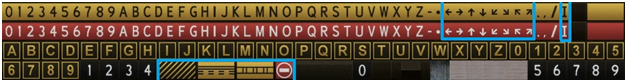
Figure 27: A chart showing all the available sign glyphs
Single glyphs are a single character, such as the letters of the alphabet, the numbers 0–9, -, *, ., and /. They do not have to be inside curly brace pairs. Single glyphs will appear on the sign as themselves, i.e. use an “A” in a name string to render “A” on a sign in X‑Plane. The only exception to this is the asterisk (*)– it will render as a bullet or dot.
Mulit-glyphs, on the other hand, can only be described using more than one symbol, and must be inside a pair of curly braces. Multi-glyphs create arrows or roman numerals, as well as special signs such as hazard and no-entry, as highlighted in blue in Figure 27 above. The following table describes the established multi-symbol glyphs and what X‑Plane will produce.
| Multi-Symbol Glyph (use inside { & } ) | X‑Plane Rendering |
|---|---|
| ^u | Up Arrow |
| ^d | Down Arrow |
| ^l | Left Arrow |
| ^r | Right Arrow |
| ^lu | Left Up Arrow |
| ^ru | Right Up Arrow |
| ^ld | Left Down Arrow |
| ^rd | Right Down Arrow |
| r1 | Roman Numeral I |
| r2 | Roman Numeral II |
| r3 | Roman Numeral III |
| no-entry | no-entry sign (white circle with horizontal bar on red background) |
| critical | ILS Critical Area Boundary sign |
| safety | Runway Safety Area |
| hazard | Taxiway Ending Marker |
| comma | The multi-glyph version of “,”. Allows commas inside curly braces. |
Curly Brace Pairs
Curly braces, { and }, are separators that make up the structure and “clauses” of the name string. Every taxi sign will use at least one pair because they are used to specify color instructions. Curly braces also surround the characters that make up a multi-glyph. There are three guidelines to keep in mind when using curly braces.
Every curly brace must have a partner. If either a right or left curly brace is missing, the sign will not be valid. For example, neither “{@Y,F” or “@Y,F}” will work as a sign name because they are both missing one of their braces. Curly braces must always have something inside them. A blank brace set, such as the one in the middle of “{@Y,F}{}{@R,T}” will cause the entire name string to not work. Finally, curly braces cannot be used in nesting situations. “{@Y,F}{@R,T{@L,1}}” would fail because {@L,1} is inside the curly brace pair for {@R,T}.
Commas have a special function when used inside curly braces–they serve as a separator for different elements of the sign name string. In the example “{@Y,F}{@R,T}” from above (with the invalid empty curly brace pair removed, of course), the commas are serving as separators of the color instruction (@Y or @R) from the text to be displayed (F & T). This example could have just as easily been written “{@Y}F{@R}T” to avoid using commas, and would obtain the exact same rendering result in X‑Plane.
Instructions
Taxi sign instructions tell X‑Plane what color the sign text will be, or to switch the text to the back side. All instructions start with “@” and must be inside a curly brace pair. All signs will start with a color instruction, then include another instruction as needed to change the color or side. The table below lists what the instruction glyph is, its resulting appearance, and what other glyphs can be used in conjunction with it.
| Instruction Glyph (use after @) | Yields | Can be used with |
|---|---|---|
| Y | “Direction, Destination, Boundary” (black on yellow) | all valid glyphs |
| R | "Mandatory Instruction” (white on red with black outline) | all valid glyphs |
| L | “Location” (yellow text and frame on black) | only alphabet & numbers |
| B | “Runway Distance Remaining” (white on black) | only numbers |
| @ | Changes sides | Switches the sign drawing from the front to the back (only allowed once per sign) |
Switching Sign Sides
Signs in X‑Plane are single-sided by default, unless the instruction “@@” is added to the name string. This merely moves X‑Plane’s taxi sign builder to the opposite side, and nothing else is affected. All glyphs following {@@} will be displayed on the back side. Note there can be only one side switch instruction per sign, for example, “{@Y}FRONT{@@}BACK{@@}FRONT” is an invalid name string.
Sign Framing
A sign “frame” refers to the separating lines that can appear between parts of a sign. Changing the sign color automatically creates a frame. Use the “|” or “pipe bar” character, found underneath the backspace key on most keyboards, to force a frame in between glyphs of the same color. See “{@Y}BOOK|CASE” on the left and “{@Y}BOOKCASE” on the right of the example below:
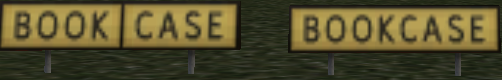
Figure 28: Using a pipe bar to frame letters of the same color
To manually insert a pipe bar, it must have the same color glyph next to it on the left and right side. For example, the name string {@Y}BOOK|{@R}CASE is invalid because to the left of the pipe bar is a yellow left arrow, and to the right is a red R. In this scenario, X‑Plane would automatically frame the two different colors, so including the pipe bar in the string is redundant.
Only use the pipe bar with glyphs that are color instructions (@Y,@R, and @L). @B is not affected by the pipe bar and as such a sign like “{@B}123” and “{@B}1|2|3” will both appear as the same image on a sign. In addition, do not put pipe bars next to each other, or at the beginning or end of a name string.
Unsupported Characters
The following table lists the characters are not supported for any reason, and will cause an error if included in a taxi sign name string.
| Unsupported | Characters | |
|---|---|---|
| ! | " | # |
| $ | % | & |
| ’ | ( | ) |
| + | : | ; |
| \ | < | = |
| > | ? | ~ |
| b | g | j |
| k | q | v |
| w | x |
Note: Taxi sign name strings are case-sensitive; therefore, B is a valid glyph but b is not.
Troubleshooting Name String Errors
The syntax used in creating taxi sign names is quite complex, which means it’s easy to make an error in the name string. Validating your airport will go a long way towards finding errors, but even this has limitations. For example, if a name string has multiple errors, they may not be revealed all at the same time, or it could incorrectly diagnose the error.
One common error message is that a character is not supported. Remember that the syntax is case sensitive, and using the wrong case may cause this error. Be alert for characters that may look alike in the name string font, for example, lowercase “L,” capital “I,” and pipe bars.
Make sure every curly brace ({ and }) is used in a pair, and only one pair, to resolve another common error message. Check that instructions and multiglyphs listed in the tables above are in curly brace pairs.
Color error messages are also common. Check that instructions have “@” at the beginning and that they are being used with their supported characters. Also ensure that instructions are always to the left of the characters that should display in that color, i.e. “{@B}123{@L}MORE” instead of “{@B}123MORE{@L}”.
If all else fails, remember there is a Scenery Development Forum at X‑Plane.org that may be able to provide help.
Table of Examples
| Name attribute and description | WED map pane | X‑Plane rendering |
|---|---|---|
Name: Taxiway identification (“You are entering taxiway A”) |
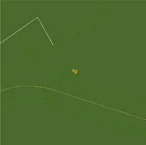 |
 |
Name: Taxiway direction (“Turn left ahead for taxiway C”) |
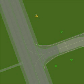 |
 |
Name: Runway direction sign (“Turn right to get to runway 17/35”) |
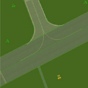 |
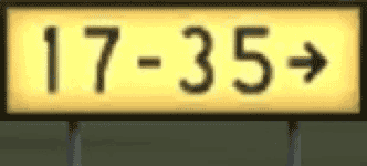 |
Name: Runway distance remaining (“1000 meters left until the end of the runway”) |
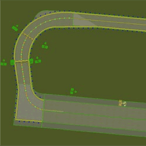 |
 |
Name: Runway hold mandatory (“Runway 11/29 ahead. Hold here for clearance to enter or cross.”) |
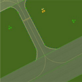 |
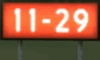 |
Name: Combined taxiway ID and runway ILS hold mandatory (“You are on taxiway B7. Runway 10 is ahead. Hold here for clearance to enter during ILS Category II or III operations.”) |
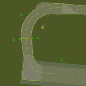 |
 |
Name: Combined taxiway ID and direction for complex junctions (“You are on taxiway C. Turn slightly left ahead for taxiway B, go straight for taxiway C, or turn right for taxiway F.”) |
 |
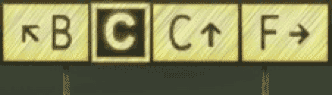 |
Name: Verbose direction sign (“Turn right ahead for the west apron”) |
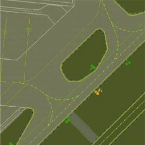 |
 |
Name: Combined taxiway ID and runway mandatory, with taxiway ID and direction on reverse side (Front: “You are on taxiway P2. Runway 16/34 ahead. Hold here for clearance to enter or cross.” Rear: “You are on taxiway P2. Turn left for taxiway P2 ahead.”) |
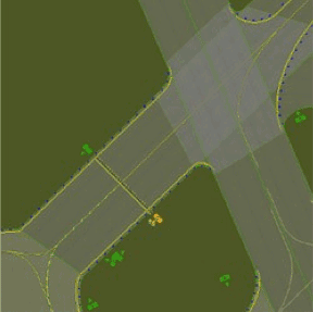 |
Front: Rear: 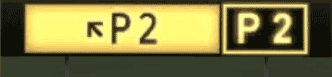 |