Intro
This tutorial will walk through the creation of an airport from scratch, including runways, taxiways, air traffic control frequencies, and more. It is related closely to the tutorial on airport customization; that document does not deal with modifying the airport data itself, and this one doesn’t deal with the terrain or objects placed on an airport.
Note that X-Plane’s official airport data is updated frequently, so you may want to check the Airport Scenery Gateway to see if there is an existing copy of the airport you’re building. For our tutorial, we’ll create data anew for Johnson County Executive Airport (KOJC), the same airport used in the Airport Customization tutorial.
This tutorial assumes you have installed the latest version of World Editor, selected an airport to work on, created a new scenery package, and familiarized yourself with the World Editor interface, all per the Airport Customization tutorial.
Remember to save often!
Getting Started
We begin with a new, empty scenery package. Before we can start laying down runways, we must first create a new airport. Open the airport menu and click Create Airport.
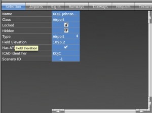
Click on the “unnamed entity” and give it a name–for our example, we’ll use “KOJC Johnson County Executive.”
Now we need the airport’s elevation. (Note that, by default, this is in feet above mean sea level. You can change these measurements to meters by clicking the Meters option in the View menu.) Using the Airnav database, we can see that KOJC has an elevation of 1096 feet above mean sea level.
After inputting the elevation, uncheck the “Has ATC” box if necessary (by default, WED assumes the airport does have ATC). Then, type in the ICAO identifier–in our case, KOJC.
Drawing the Main Runway
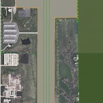
Now let’s draw the main runway. Using the Airnav database, we found that our example airport has its northern end at 38.8532228333 N, 94.7375677167 W, and its southern end at 38.8419830833 N, 94.737600583 W. We can use these coordinates, together with the mouse pointer coordinates at the bottom of the scenery editing pane, to zoom in on our airport.
Note that you may need to convert between degrees-minutes-seconds of arc to decimal degrees. In doing so, remember that there are 60 minutes of arc to a degree, and 60 seconds of arc to a minute, or use an online converter tool such as this one from the FCC.
Note also that you can place an orthophoto guide according to the Airport Customization tutorial to help visually check your scenery.
Now we will draw our runway. Select the Runway tool from the toolbar. Click once on one end of the runway, then again on the other end. For the sake of consistency, we recommend clicking first on the northern or western end (depending on the runway’s orientation) and clicking second on the southern or eastern end. Note that, for now, this does not have to be very precise–we’ll clean it up momentarily to make it pin-point accurate.
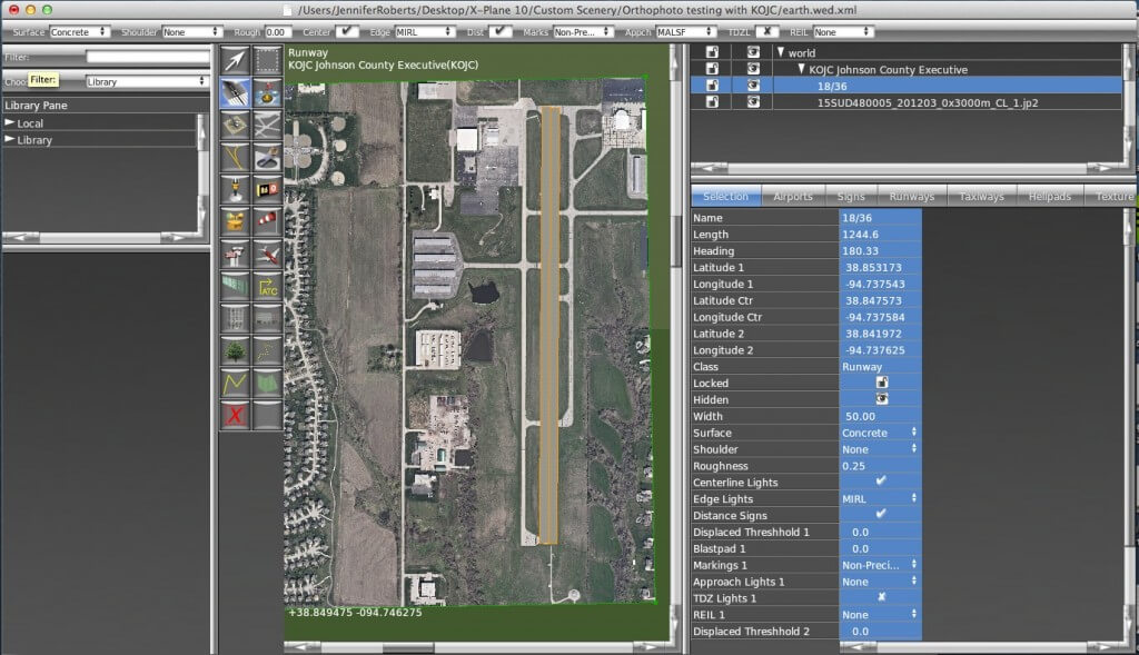
After your second mouse click, the green drawing line will turn into an orange outline, and the runway will appear in the object hierarchy pane, with a long list of attributes below it. Using data from Airnav (or another source if you prefer), you will need to input all the airport’s attributes. You should begin with the “Latitude 1” and “Longitude 1”–these are the coordinates of the first end you drew previously, which should have been the northern or western end of the runway. Then, input the “Latitude 2” and “Longitude 2” coordinates. (Note that the Latitude/Longitude Center, the Heading, and the Length attributes will all be calculated automatically from these.)
Beyond these attributes, the order in which you input the data does not matter. At the very least, you should specify the runway width, the surface, and, of course, the name.
Note that, for all attributes with “1” and “2” variants, the “1” end is the end you clicked first when drawing.
Some important attributes whose significance may not be obvious are:
- Roughness: this specifies how rough the runway is (and how much it bumps the plane around) when taxiing. This is on a scale from 0.0 to 1.0. A runway in good condition should have a roughness of about 0.25.
- Displaced Threshold 1 and 2: these specify how far from the end of the runway an aircraft is allowed to touch down, measured in feet or meters depending on your settings in the View menu. By default, the threshold is the end of the runway, so this is set to 0.0.
- Shoulder: this sets the surface type of the runway shoulder, which is a small section of pavement beyond the runway found mostly in large airports.
- Edge lights: runway edge lights are classified by the intensity of the light they produce. They can be HighIntensity Runway Lights (HIRL), Medium Intensity Runway Lights (MIRL), or Low Intensity Runway Lights (LIRL), or the runway may have no edge lights at all.
- Markings 1 and 2: these specify the type of markings on each end of runway. Read more about these on Wikipedia.
- Blast pad 1 and 2: these specify the length (in either meters or feet) of the blast pad. A blast pad is an area of pavement at the end of the runway constructed to keep dirt and grass from being blown around in the jet blast created by a large aircraft taking off.
- Approach lights 1 and 2: many configurations exist for a runway’s Approach Lighting System (ALS). You can read about them here.
- REIL 1 and 2: the Runway End Identifier Lights.
- TDZ lights 1 and 2: the Touch Down Zone lights.
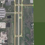
Our finished runway for KOJC looks like this:
Repeat these steps for the creation of any other runways. You may want to lock the runways (by clicking the lock symbol next to them) in order to prevent accidental editing later.
Creating the Airport Boundary
After creating your runways, select the Boundary tool (labeled with an image of a fence) from the toolbar. Click at each corner around the airport to draw the boundary. This is the area that will be flattened in X-Plane when the rendering options are set to do so.
Be sure to go in one direction–either all clockwise or all counter-clockwise. When you have placed the last corner, press the Enter key to commit the points to the boundary. At this point, the boundary will appear in the object hierarchy pane; you can then name it there.
If your points aren’t in the places you would like, you can use the vertex tool to click the points and drag them.
Setting the Tower Viewpoint
Select the Tower Viewpoint tool from the toolbar, and click where the air traffic control tower sits (as seen in the image below).
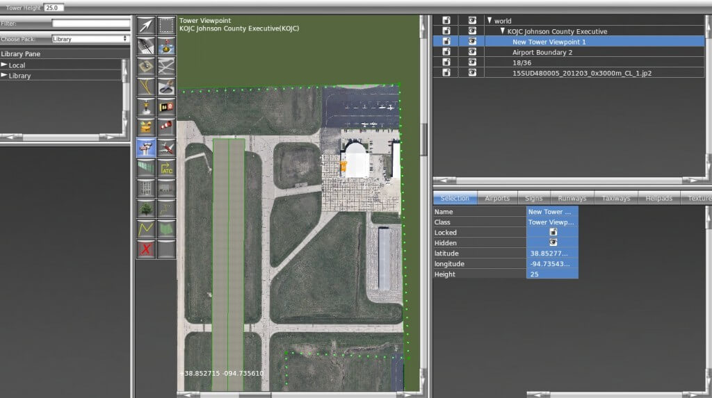
If there is no physical tower, as is the case in many smaller airports, set this to the main terminal. If this viewpoint is not set, selecting the tower view in X-Plane will put the view right on the runway.
After setting the viewpoint, be sure to set the Height attribute.
Creating Communication Frequencies
After creating your runways, highlight your airport in the Hierarchy pane by clicking on it. Open the Airport menu and click Create ATC Frequency.
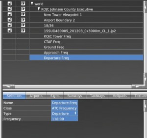
An “unnamed entity” will appear in the object hierarchy pane. Name this one something like “[Airport] Tower Freq,” and set its attributes properly (once again, this information can be found in the Airnav database). For instance, we found that KOJC’s tower uses frequency 126.0, so we set its attributes accordingly.
Repeat this for all the communication frequencies present in your airport, using the Type attribute to specify which frequency it is. In our example airport, we have 5 different radio frequencies to set up, using the Type attributes CTAF, Tower, Ground, Approach, and Departure. In the following image, we have set the KOJC Departure Freq to Departure type and are setting its frequency at 118.9.
It may be helpful for the sake of organization to group these communication frequencies together. To do so, highlight the frequencies you want by clicking them while holding down the Ctrl key in Windows or Command key in OS X. With them all selected, go to the Edit menu and click Group.
Name this new group, and we’re ready to move on.
Drawing Taxiways and Other Pavement
Now let’s draw your taxiway(s) and other pavement (aprons, parking lots, etc.). We will use the Taxiway tool to do all this–X-Plane doesn’t care that a layer of asphalt might actually be a parking lot.
Note: when drawing these polygons, make sure there is only one enclosed area per polygon–that is, make sure that the outline does not cross over itself at any point.
With this in mind, select the Taxiway tool from the toolbar and click around the outside of your paved areas. At this point, you should not be making the shapes look pretty–use a small number of nodes, with the intention of cleaning the shape up later. Note especially that you do not need to pay special attention to curves–soon we will create bezier curves to follow the contours of the pavement, but don’t worry about it now.
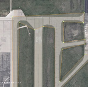
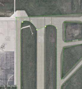
The best way to do this is to outline all the taxiways and other pavement in your object, then use the Hole tool to cut out all the area that gets selected which isn’t pavement. When you finish drawing each item, press enter–you should have a few objects that look similar to those in the image below. This will not work if you need markings on your (true) taxiways, though–in that case, you’ll need separate objects.
If you are using an orthophoto, it will be helpful to change the transparency of the taxiway in order to see where the holes should be drawn. To do this, click the View menu and select “Pavement Transparency.” Set the taxiways to 50% transparency for a good balance.
In the image on the left below, the taxiway has just been drawn–it covers a lot of area that it shouldn’t. Then, in the image on the right, holes have been cut in it so that it doesn’t cover the grassy areas around it. It still isn’t pretty, but we’ll clean it up soon to more closely match the real taxiways.
Smoothing the Curves
Now that we have (very) basic outline of our pavement drawn, we need to modify it to follow the contours of the actual airport’s curves. We’ll do this by turning the node near a corner into a bezier node, which will cause the line connected to it to curve around it.
You may need place an extra node between two points for the purpose of creating this bezier node. To split the line connecting two points and place a node between them, highlight the points using the vertex tool, open the Edit menu, and click Split. Alternatively, you can highlight the points and press Ctrl+E in Windows, or Command+E on a Mac.
For instance, in the image below, we split the line between the node on the left and right, then used the vertex tool to drag the new node down to the pavement.
Now, to turn this into a bezier node, hold down the Alt key and drag the mouse away from the point. After you let go of both the mouse and the Alt key, you can click and drag the outside arrows to further tune the curve.
From here, you can click and drag the arrows attached to the node to further modify the curve. A completed curve will look like the above image.
For information on switching between the different types of nodes, see the World Editor manual. The section on creating shapes may be particularly helpful.
Repeat this process for each curve around the pavement.
Creating Markings and Lighting
Now we will add markings to our runways, taxiways, and other pavement. Markings come in two varieties–perimeter markings (found around the outline of taxiways), and overlay markings (like taxilines, ILS, and hold short markings).
Note that whenever you select a tool that supports markings (i.e. the taxiway and taxiline tools), you’ll notice some options appear at the top of the scenery editing pane. One of these options are markings. When you select a marking in this pull-down menu, that marking will be applied to that tool until you change it. So if you were going to draw taxilines, you’d select the taxiline tool, then set the Markings to Double Solid Yellow (Black) and begin drawing the shape.
You can, however, draw the shape first and add the markings later. This is easily accomplished by selecting the entity, with either the vertex tool or the marquee tool, then going to the attributes pane and setting the Line Attributes, Light Attributes, or both. When you do this, the markings will be applied to the entire shape. This is generally not what is desired, though, and you’ll need to remove the markings from some of the segments for taxiway intersections and the like.
To remove the markings from one section of the taxiway, select a single node using the vertex tool. Then, in the attributes pane, set its Line Attributes to none. The line connecting this node to whichever node was drawn after it will no longer have that attribute. For instance, if you selected Node 9 and set its Line Attributes to none, the line connecting it to Node 10 would have no markings.
Adding the Finishing Touches
We have just a few more things to add to the airport for it to be ready to go.
Creating Runway Signs
To create a runway sign, select the Sign tool from the toolbar. Click where you would like to place it, then drag your mouse around that point to orient it in the direction it needs to go. Note that the arrow coming out of the sign indicates its heading. To move a runway sign, use the marquee tool to click and drag it. To change its heading, drag it with the vertex tool.
For information on setting the text on the sign, and for examples of the text used, see the WED manual appendix on defining taxi signs.
Creating Windsocks, Light Fixtures, and Airport Beacons
Windsocks, light fixtures, and airport beacons are all placed on the airport like runway signs–click to place them, and, in the case of the light fixtures, drag the cursor to change their orientation. You can use the marquee tool to change their position, and, for the light fixtures, you can use the vertex tool to change their heading.
Adding ATC Flow and Taxi Networks
If you are customizing a large or busy airport, it is a good idea to specify the taxi network the airport should have, as well as the ATC flows. A taxi network you create is more likely to be realistic than the one X-Plane can automatically generate. Most large airports will also have several “flows” depending on weather or time conditions, or type of aircraft
To add an ATC flow item, select your airport in the hierarchy pane, open the Airport menu, and click Create Airport Flow. Then, after selecting that flow in the hierarchy pane, open the Airport menu again and select Create Runway Use Rule, Create Runway Time Rule, or Create Runway Wind Rule.
These rules specify under what conditions the runway should be used. X‑Plane will try to use the rules in order (from top to bottom), so be sure to order multiple flows from most specific to least. It also a good idea to have a generic, catch-all flow that can be used in all conditions in case the condition-specific flows overlook a possible scenario.
See the see the four part video tutorial for more information on airport flows.
To create taxiway routings for the AI aircraft, select the taxi routes tool. Set your properties at the top of the window, then click to trace the path aircraft should take. The Departure, Arrival and ILS fields set up hold short parameters. The slop field indicates how close your point must be to another taxiway section in order to snap to it. Larger numbers allow the paths to snap together from farther away. The other preset fields are self-explanatory.
Check for degenerate edges, double nodes, and crossing edges before exporting an airport with a taxi network. These are found under the Select menu and will show any errors in the attributes pane.
A five part video tutorial is also available.
Exporting Your apt.dat File
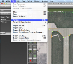
Before exporting your airport data, open the File menu and click Validate, as shown in the image below.This command will check the WED file for errors based on the current export target. You can change the export target by selecting Target X‑Plane Version from under the File menu. Remember that selecting a version older than 10.0 might disable newer features, such as ATC data.
If no errors are present, select Export Scenery Pack from the File menu. The new scenery will be visible the next time you load the area in X‑Plane.
Alternatively, with version 1.3 of WED and newer, you can upload your scenery creation directly to the Airport Scenery Gateway. See these instructions to register first.