Revision History:
         01/26/18   Updated with Joining Taxiways to Runways
         06/25/08   Updated With Taxiline Guidelines
         10/25/07   Initial Draft
Correct Formation of T Junctions
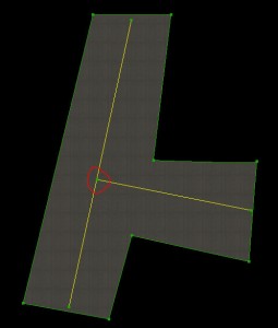
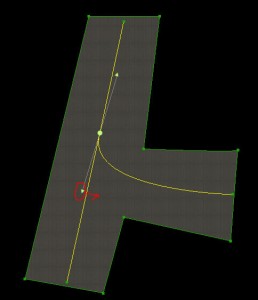
A “T” junction is any connection between lines in an airport layout where one line ends in the middle of another line. T junctions would include a T-shaped meeting of taxiway lines (shown in these examples), but the junctions formed by the edges of taxiway pavement are also T junctions and need to be formed using the same technique.
The key points are:
- Two lines in a WED layout (of any type) should always meet at their endpoints.
- One line should not end in the middle of another line.
- This means that you must split a line at the point another line intersects it.
You should not simply attempt to visually line up your layout. Consider this T junction:
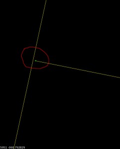
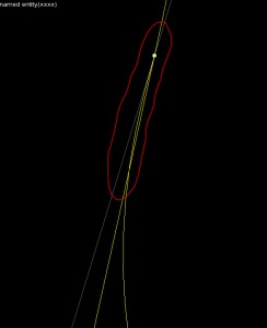
It looks correct but upon zooming it becomes clear that the taxiway line ends “near” the next line but is not actually on it. With no vertex to join to, this join can never be clean.
Junctions like this can suffer from all sorts of problems in X-Plane:
- The alignment error may look significantly worse in the sim–the only way to guarantee a good connection is to have two vertices with the exact same location.
- If one of the lines is a bezier curve, the approximation of the bezier in X-Plane may be different from WED, causing a disconnect.
- If these lines were taxiway edges, the “sliver” of a gap could cause bumps when a plane rolls over it or ugly rendering errors in the pavement.
The correct way to build a T junction is a two-step process.
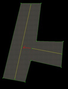
Split one of the lines so there is a vertex at the location where the two nodes will meet. :
Then drag the connecting line to that vertex. In WED you can use the “snap to vertex” option to get precise positioning of the two vertices on top of each other. :
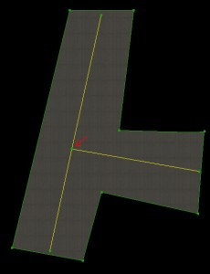
This T junction will look correct at any zoom, and will render correctly in X-Plane.
Remember: close visual alignment in WED is not good enough! You must create an extra vertex and snap the vertices together to create precisely aligned layouts.
Correct Bezier T Junctions
When a T junction is made up of a bezier curve, another issue comes into play: besides needing the end vertices to be snapped together, the bezier curve handles must not be “over-curved”. Consider this layout:
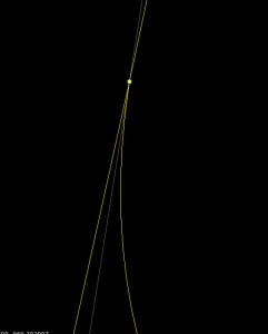
It looks okay in WED, but note that the lower control handle of the bezier curve is on the left side of the straight taxiway line (and yet the bezier curve itself is on the right side. This is a mistake in the layout! Here’s what it looks like close up:
The problem is that the bezier curve control handle (by being on the left side of the taxiway line) pulls the bezier to left a little bit too much. The result is that the bezier crosses over the centerline before joining with it. This error looks small in WED, but in X-Plane, where the taxiway lines aren’t as smooth, the error is significantly more noticeable.
In order to fix this problem, the lower bezier control handle must be on the same side of the joining line as the curve itself–in this case on the right side.
This creates a bezier curve that looks good no matter how closely it is zoomed.
The key here is to err on the side of caution: position the bezier control point on the right side of the connecting line; do not trust the preview of the curve to show if there is a problem.
Do Not Add Extra Vertices to Make Smooth Curves
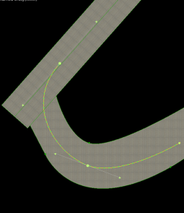
You must add vertices to make T junctions correct. However, you should use the smallest number of vertices possible to correctly describe your layout. For example: this is a bad taxiway line.
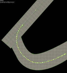
The taxiway line is bad because it uses a huge number of vertices – way more than necessary. The line should be built like this:
Use a small number of bezier curves to shape your lines. Do not add extra vertices in an attempt to make the line look smoother in X-Plane.
X-Plane uses an “error” heuristic to draw taxiway lines–basically it will add vertices to minimize the “squareness” of lines. The problem with adding vertices is that you have to add a very large number of vertices to force X-Plane to render at a higher quality. If you add a few vertices, you increase file size, download time, load time, and RAM use, and X-Plane simply adds fewer of its own points (since fewer are needed to reach the same amount of roundness). Only by adding an insane number of vertices can you markedly improve visual quality; this comes at the expense of RAM use for your layout.
Leave smoothness of lines up to X-Plane; this setting will be wired to the user interface. Some users will need lower rendering quality to use your airport on slower computers. If you add too many vertices, you simply assure that these users cannot fly to your airport at all.
Joining Taxiways to Runways
Taxiways should be drawn to the runway edge, not just to the runway shoulder edge:

Connecting the taxiway to the runway in this manner will result in correctly recessed runway edge lights and a better looking connection between the pavements. The taxiways are automatically drawn above the shoulders and below the runways. If you stop the taxiway at the shoulder edge, it often leaves a gap between the runway pavement and the taxiway.