In this tutorial, we’ll walk through the creation of an airplane–specifically, a Beechcraft A36 Bonanza–from start to finish using Plane Maker. No prior knowledge of the Plane Maker software is required, though familiarity with the X-Plane simulator itself is assumed.
You can download the example aircraft referenced throughout this tutorial here: A36.zip
Choosing an Aircraft, Researching the Design
Plane Maker can be used to model a tremendous variety of aircraft. For the purposes of this tutorial, though, we suggest choosing a straightforward design to model. Our example craft is a Beechcraft A36 Bonanza.
In the course of creating the aircraft file, you will need a good deal of information on the actual plane, including its physical dimensions, engine and propeller specifications, weight, fuel capacity, fuel tank locations, limiting and recommended airspeeds, and so on. A web search should turn up this data for most popular planes.
Beginning the Project
To begin creating the aircraft, open the Plane Maker application found in your X-Plane installation directory.
When the window appears, open the File menu by mousing over it and click New. This will create a new, very basic aircraft file. Then, open the File menu again and click Save As. We will save our example aircraft in the “BonanzaA36” folder which we created in our X-Plane installation directory, and we’ll name it “A36.”
We’ll begin by setting a few basic parameters for our aircraft in order to the avoid the warning that pops up every time you save.
Setting the Aircraft’s Details
Open the Standard menu and click Viewpoint. The most important settings here are for the aircraft’s limits (found on the left side of the window in the Default tab). With the exception of the G-limits, these will not be factored into the flight model; they may, however, be used in the airspeed indicator. These limiting velocities are not hard to find, either in the pilot’s operating handbook or on the Web.
If you can’t find official G-limit values, 4.0 is a good guess for most general aviation aircraft. At G-loads more than 50% above these values, if the appropriate settings are enabled in X-Plane, structural damage will occur–probably in the form of a wing being torn off!
Setting the Weight and Balance
Next, open the Standard menu and click Weight & Balance. In the Center of Gravity section of this window you can set three longitudinal positions for the center of gravity, along with one vertical position. The center of the longitudinal positions is the default, while the outer two are the forward and aft limits. The center of gravity can be modified within these limits in X-Plane.
Beneath the Center of Gravity box is the Weights box. The empty weight, fuel load, and maximum weight can all easily be found from the manufacturer. Set these parameters now.
Now move to the Tanks tab of this window. There are 9 different fuel tanks available, each one holding a ratio of the maximum fuel. Note that the ratios must add up to 1. For our example Bonanza, we have two fuel tanks, one in each wing, each holding 0.5 of the total fuel. Position each tank’s center of gravity using the standard longitudinal-lateral-vertical positioning relative to the reference point.
Making A Fuselage
Preparations
If you are not familiar with the basic views and controls in Plane Maker you can review them in the section “Working with the Views” found in the Plane Maker manual.
Unless you have physical access to the aircraft you’re designing, you’ll want to find scaled images of the craft to use in the design. We found front, top, and left views of our A36 Bonanza on the Beechcraft website. These will be used as background images with which to align our design.
For use with the fuselage creation, crop your top and left images down to just the fuselage, being sure that the images are the same size and are both centered on the fuselage center.
Setting the Basics
With the images ready to go, open the Standard menu and click Fuselage.
In the window that appears, we’ll set the Body Data section first.
The number of stations corresponds to the number of individual sections that Plane Maker will link together to form your aircraft body, with a maximum of 20. You’ll probably want to add 2 to the number of sections you had in mind to account for the two closed ends. In our case, we will use a total of 15 sections: 13 “real” divisions, which meet at a point at each end (adding 2 extra cross sections).
The number of radii per side is the number of points used on each side of the cross section. Unless your aircraft has a very simple shape to its body, you’ll probably want to use the maximum of 9.
The body radius setting controls the width of the cross-section views below. Keep this close to the actual max body radius for accuracy when placing your points, but err on the side of setting this too big so that all your points are visible.
Finally, the body coefficient of drag controls the amount of drag generated by the fuselage. An average fuselage will have a coefficient of drag of 0.1, while a very sleek one will have a coefficient of 0.05. We didn’t have any official data on this for our Bonanza, so we chose an approximate value of 0.075.
Setting the Length
While still in the Section tab of the Fuselage window, look directly above the cross section boxes. The parameters there set the distance of each cross section relative to the reference point. The reference point can be whatever you want. Many people use the aircraft’s nose. For our example, we’ll make it the aircraft’s center.
Note that negative numbers along the longitudinal line of the aircraft (like the parameters for the cross-section placement) indicate a position forward of the reference point; positive numbers indicate a position behind the reference point.
At this point, we will set the approximate distances from the reference point for each of our cross sections (as in the image below). The most important of these will be the first and last cross sections. Since our example aircraft’s reference point is its center, the forward-most point of our aircraft will be set at -13.50 feet, and the rear-most point will be at 13.50 feet. Taking these two together, we have a 27-foot fuselage. The aircraft’s official length is 27 feet 6 inches, but since we will build the housing of our propeller separately, this should be about perfect.
With the fuselage’s length properly set, move to the Top/Bottom tab. At the bottom of the window, click Load Top Background Bitmap and select the image of the top that you worked with in the Preparations section above. Then, click the Load Left Background Bitmap button and do the same for the side image.
At this point, since the fuselage has the correct length, we need to align its two ends with the ends of the fuselage in the background images. Use the – and = keys to zoom the 3-D models out and in, and use the arrow keys to move them around.
You will likely want to return now to the Section tab to fine-tune the distances set for your cross-sections.
Setting the Radius Points
With the distances properly set, move back to the Top/Bottom tab. There, drag the radius points evenly around the fuselage visible in each of the three sections. You will likely want to use the buttons in the top right of the window to occasionally reset the cross-sections to be vertical. Note: You will likely find the Ellipse buttons (found near the bottom of the screen) helpful. Clicking this for a given cross-section will shift its points to a best-fit ellipse. To lock a point from further automatic shifting, just double-click on it (it should turn a sold black color). This may be helpful once you have them correctly established, especially the center line of each frame in the Top/Bottom tab.
Move occasionally to the Section and Front/Back tabs to check how the cross sections look from other views. You will probably find the best workflow to be something like this:
- In the Top/Bottom tab, match the outer points to the fuselage edges in each of the three views.
- Distribute the middle points evenly between the outer ones in each of the three views.
- Move to the Section tab and modify cross sections to conform to the shape you know they should have. For instance, with our A36 Bonanza, we knew its bottom was completely flat in the middle of the plane.
- Move to the Front/Back tab to fine-tune the points that are very close together.
- Repeat as needed.
Eventually, your points should look something like this:
When you’re finished, close out of the Fuselage window and load up your background bitmaps one at a time (using the button in the bottom left of the screen). Check your fuselage against each one. (Tip: use the Background menu to select whichever view you have loaded in the background.)
Designing the Wings
Now that our fuselage is finished, let’s move on to the wings. Open the Standard menu and click Wings.
In this window, you can specify four wings, a horizontal stabilizer, and two vertical stabilizers. The wings will be mirrored on each side, as will the horizontal stabilizer, whereas the horizontal stabilizer will of course only be created once. Other than this, each of the flight surfaces here behave identically.
Note that if you need more wing sections than what is available here, the Misc Wings window (which is also found in the Standard menu) allows you to specify up to 20 additional wing sections.
Creating the Main Wing
For our example Bonanza, we’ll use three wing sections, with each section meeting the one closer to the fuselage, in order to model the single wing of the actual aircraft. Each wing section can have two different airfoils set for it (one for the root and one for the tip, which are blended together in the center), as well as different control surfaces.
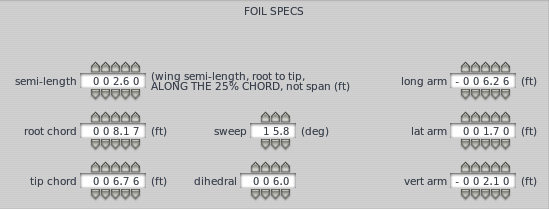
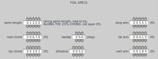
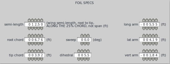
For the initial creation of each wing section, you can focus exclusively on the Foil Specs section of the window. You can enter these parameters visually if your top view scaled background image is loaded and your Plane Maker window is wide enough.
Let’s talk about these parameters a little.
The semi-length parameter sets the length of each side of the wing as measured through the center of the wing, from the root to the tip, 25% behind the leading edge.
The root and tip chord set the width of the wing at the root (closest to the fuselage) and tip (farthest from the fuselage), measured from the leading to the trailing edge of the wing.
The sweep parameter sets the angle (in degrees) that the wing is angled back.
The long, lat, and vert arm parameters set the wing’s position relative to the reference point. See the diagram to the right illustrating the longitudinal-lateral-vertical positioning system.
The dihedral parameter sets the angle (in degrees) that the wing is angled up. For instance, in the image below, each of the 3 wing sections used has a dihedral set between 5.5 and 6 degrees, causing the wings to angle slightly up.
Example Wings
The image below shows the foil specs used to create our innermost wing section in the G36 Bonanza. Note the 15.8 degree sweep, which creates a relatively sharp backward angle for the section.
This creates a wing section that looks like this:
The next image shows the foil specifications for our middle wing section, entered on the Wing 2 tab. This section is significantly longer than the base one–it has a semi-length of 12.5 feet, compared to 2.6 feet. Note also that, unlike the base wing, our mid-wing has a lateral arm specified. This moves the wing’s root out away from the body, so that it meets up with the base wing’s tip. You can have the section “snap to” the previous section by selecting Right Wing 1 from the drop down box in the top right corner of the dialog, instead of setting the wing section’s location manually using the long, lat, and vert arm boxes.
This creates a wing section that looks like this:
Click on the Wing 3 tab to finish the tip of the wing with the specs shown in the image below.
Creating the Horizontal and Vertical Stabilizers
The horizontal stabilizer is specified just like the previous wing sections; the only difference is that it will have a much higher value for its longitudinal arm than the previous wings.
The vertical stabilizer, unlike the other wing sections here, is not mirrored on each side of the aircraft. Other than this, and its default dihedral of 90 degrees (so that it sticks straight up), you can set it just like the previous wings.
Setting the Airfoils
With your wings created, close out of the Wings window. Open the Expert menu and click Airfoils. In the Airfoils window, go to the Wings tab. Here, you can set two versions of both the root and the tip airfoil for each wing section. The foils on the left are for the root side of the section, and the ones on the right are for the tip side, as seen below.
Plane Maker will interpolate between these two foils in the middle of the wing section. The top set of foils in each wing’s box specify the low Reynolds number version of the foil; the bottom set specify the high Reynolds number version.
The following two pages may be useful in determining what airfoils to use in your wing:
To set an airfoil, click the gray box to the left of it to open your X-Plane Airfoils directory folder. Select an airfoil from among the list then click the Open Airfoil button. Remember that our wing is made up of three separate sections, so you will want to choose the same “wing root airfoil” for all four boxes for Wing 1 and Wing 2. Set the boxes of Wing 3 to the “wing tip airfoil” as it functions entirely as our wing’s tip.
Setting the Control Geometry
With the wings and their associated airfoils set, it’s time to set up the control surfaces. To do this, open the Standard menu and click Control Geometry. In the window that appears, a number of possible control surfaces can be specified, from ailerons to elevators to rudders to speedbrakes to flaps. Each of these work in a similar way.
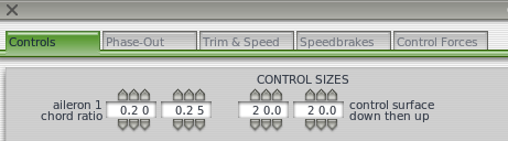
In the image above, the parameter on the far left sets the control surface’s root-side width as a percentage of the root width of whatever wing section it is placed on. Thus, if this were set at 0.50 and it were used in a wing whose root was 5 feet wide, the control surface would have a root width of 2.5 feet. To the right of the root width is the tip width, also specified as a percentage of the tip width of whatever wing it is placed on. These two parameters are the same on each of the control surfaces available. Start with an amount close to the default recommended by the mouse over text.
To the right of the size parameters are the parameters controlling how far the surface can move. This will be different for each aircraft, but again start with the defaults recommended. You may need to return to this window after your first test flight to fine-tune it.
With this knowledge, specifications for ailerons, elevators, and rudders are all fairly straightforward. At the bottom of the Control Sizes box is the control surface type setting, which modifies how effective the surfaces are in X-Plane. Surfaces which are corrugated with gaps are least effective.
In the right half of this window are the flap settings, as seen in the image to the right.
Here, you can set the root and tip width ratios like the other control surfaces. You can also specify the flap type and the aerodynamic coefficients for each flap. Plane Maker will calculate the coefficients of lift (Cl), drag (Cd), and moment (Cm) based on the size of the flap, but these may be modified manually.
Beneath the coefficients, you can set the flap deflection time, the number of detents (or stop points), and the deflection at each detent. In our example, the maximum flap deflection is 30 degrees, so that is set in the last box. The first box is 0 for no deflection, and the remaining boxes in between are spaced evenly (in our case, 10 and 20 degrees).
For our example Bonanza, we specified one aileron type, one elevator, one rudder, and two flaps. We now need to add them to our wings.
Adding the Control Surfaces to the Wings
In order to see the control surfaces once we add them, open the Special menu and click Show with Still/Moving Controls. This will make the control surfaces move as we add them, so that we’ll better be able to judge where they are.
Now, open the Wings window from the Standard menu once again.
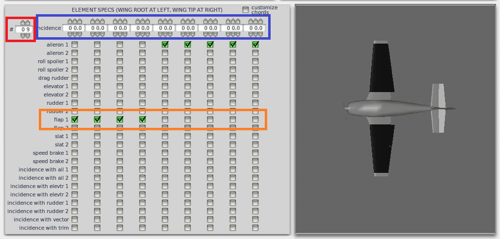
In the Element Specs box for each wing section, you can control:
- the number of pieces that this wing section will be divided into (using the parameter highlighted in red in the image above),
- the incidence, or upward angling, of each “piece” (using the parameter highlighted in blue), and
- the control surface (if any) present in each “piece” (using the parameter highlighted in orange).
For instance, in the image above, the middle section of our main wing is divided into 9 “pieces,” all with zero incidence. The first four pieces (the four closest to the fuselage) use the flap 1 control surface, and the last 5 pieces (the five farthest from the fuselage) use the aileron 1 control surface. Both of these control surfaces were specified in the Control Geometry window and were fine-tuned after seeing how they looked here.
Set your control surfaces as you need them for each wing section. Our Wing 1 had 8 sections with the flap 2 box checked for all but the first piece (where the wing would attach to the fuselage). Wing 3 does not move in our Bonanza so despite having multiple pieces, no control surface boxes are checked. The horizontal stabilizer is where the elevator boxes are checked and the vertical stabilizer has the rudder boxes checked.
Adding the Engine
With the wings and their associated control surfaces finished, it’s time to add an engine. To do this, open the Engine Specs window, found in the Standard menu.
When the window opens, it will be in the Description tab. Let’s talk about the Critical Altitude box first. If your aircraft has a turbocharged reciprocating engine or a “down-rated” jet or turboprop, use the critical altitude parameter to set the maximum altitude at which the engine can put out its maximum allowed thrust. If the engine has a Full Authority Digital Engine Control (FADEC) system, check the appropriate box. Our Bonanza has neither, however, so we will leave these alone.
In the Prop Engine Specs below, you can set the engine’s maximum allowable power. For our example A36 Bonanza, this is 300 horsepower. Beneath this control are the various engine RPM settings. Note that the top of green arc and redline parameters should probably be the same. If it is a fixed-RPM engine, these should be the RPM the engine runs at. Also, the bottom of green arc should be set to zero for fixed-RPM engines.
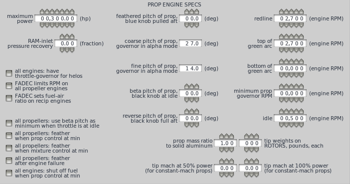
The rest of the prop engine settings are self-explanatory. Once these are set, move to the Location tab. Here, you can set the details of the engines and propellers, including how many there are, their type, location, RPM, etc. The parameters available here will vary depending on what type of engine you set. At the minimum, you will set the location in longitudinal-lateral-vertical arms for the center of thrust (which, for a propeller based craft, is just the center of the propeller).
Unless you have multiple transmissions or propellers, you can ignore the Transmission tab. Unless you have specific numbers on the engine’s specific fuel consumption or the propeller’s dimensions and angle of incidence, you can safely ignore the rest of the tabs here, too.
Creating an Engine Nacelle
If you created the aircraft fuselage like we did in the example Bonanza, you left off a few inches from the fuselage for the propeller and its housing. We’ll add this now around the propeller.
Open the Standard menu and click Engine Nacelles. In the window that appears, check the aircraft has a nacelle over this engine box, found near the top of the screen. From there, you can design the nacelle just like you did the fuselage. This time, though, the distances will be relative to the engine’s center of thrust, not the craft’s reference point. In our example Bonanza, we needed 6 station and 6 radii per side to model the propeller housing, with a body radius of 0.07 feet.
While designing the nacelle, you will likely find the Ellipse buttons (found near the bottom of the screen) helpful again. Clicking this for a given cross-section will shift its points to a best-fit ellipse. To lock a point from further automatic shifting, just double-click on it (it should turn a sold black color).
When you’re finished creating the nacelle, you should see the aircraft really beginning to take shape. All that’s left is to create the landing gear!
Creating a Landing Gear
Open the Standard menu and click Landing Gear. In this window, you can add up to ten different gears. For each gear, you must specify (listed in order from top to bottom in the window):
- its type (e.g., skids, single wheel, double wheel in a lateral line, etc.),
- its position (in longitudinal-lateral-vertical feet from the reference point),
- its latitudinal and longitudinal angles when extended and retracted (where applicable),
- its leg length,
- its tire radius and width,
- its steering ability,
- the degrees that the wheels spin when retracting,
- the distance that the strut compresses when retracting,
- the time it takes to retract or extend the gear,
- whether or not it brakes, castors or has fairing.
For our example Bonanza, we created 3 landing gears with the parameters shown below.
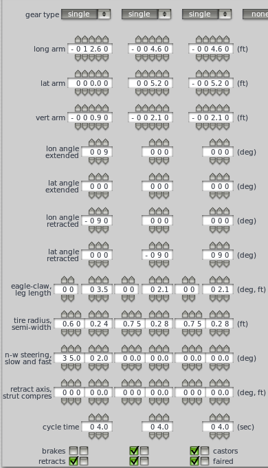
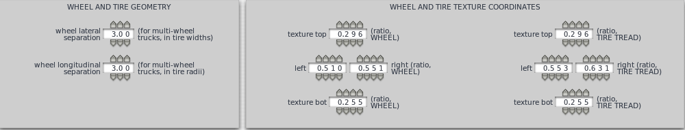
To finish the gear, you must go to the Gear Data tab and enter the specs for the wheels and tires, as shown below.
The Test Flight
At this point, you aircraft is ready to be flown in X-Plane. It won’t be pretty (we haven’t added any overlay graphics or objects), and it won’t have any instruments in its panel, but it should fly just fine. Load up X-Plane, fly the plane around a bit to see how it handles, then return to Plane Maker to tweak it as needed.
Good luck!
Further Reading
For information on creating a panel for this aircraft, see the panel creation tutorial. For information on adding a paint job to the aircraft, see the paint texturing tutorial.
The latest version of the Plane Maker manual is always available online.