This article will walk through the creation of two basic facade files. Before beginning this tutorial, be sure you’re with the facade concepts and terminology found in the Facade Overview.
Getting the images
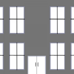
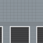
To begin, we’ll need images to use with our facade. For the purpose of the tutorial, we have two very rudimentary facades that were drawn in Photoshop. In your own facades, you can either do the same (drawing from scratch in an image editor), or you can use photos of real buildings–for instance, the buildings actually present at the airport you’re working on. Be sure that any photos you want to use are taken facing the building straight on. It will be difficult to set an image straight with any degree of realism if it was taken at an angle.
Note that your image files may be either PNG, BMP, or DDS format. The images do not have do be square. However, their dimensions in pixels must be a power of 2, as with all images used in X-Plane scenery.
Download the images for the tutorial here:
Understanding S-T coordinates
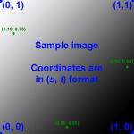
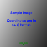
All image coordinates in X-Plane are specified in OpenGL’s S-T system. Within this system, every pixel in an image has a unique coordinate specified as a proportion of the width and height. This means that each dimension of the coordinate is between 0 and 1.
These coordinates are ordered as (s, t), which is (proportion of width, proportion of height).
The coordinate (0, 0) corresponds to the bottom left corner of the image, and the coordinate (1,1) corresponds to the upper right corner. Even if the image is not square, this is still true; the s coordinate is a proportion of whatever the width is, and the t coordinate is a proportion of whatever the height is.
Click on the images below for help in understanding this system:
Writing the facade file
The facade file itself is a text file containing information on the image and how it should be utilized in X-Plane. Let’s get started writing this file.
Create a new text document using your favorite text editor (e.g., Notepad, Emacs, Vi, etc.). Save it as FacadeNameHere.fac. In our example facades, we called them basichangar.fac and basicbuilding.fac.
Note: Except where noted, each line in the text file must be present exactly once–it may not be either omitted or repeated.
Specifying the file type
The first three lines of this text file should always be:
A
1000
FACADE
These lines tell X-Plane that it is indeed looking at a facade file.
Specifying which image(s) to use
Immediately following that is the line specifying the image resource to use. The image name should always have a path relative to the FacadeNameHere.fac file. For instance, in this example (taken from our example hangar facade), the image is in the same folder as the .fac file:
TEXTURE hangar.png
This is the recommended way to set up your folder, as it is the simplest way to do it.
If you have a so-called “lit” texture (a texture to be used at night, when the building would be lit artificially), you can use the following command immediately after the TEXTURE line:
TEXTURE_LIT ImageNameHere.png
The TEXTURE_LIT line may be omitted, as it is in our examples.
Setting the facade’s details
Following the TEXTURE command(s) is the RING line. If this is set to 1, the facade will form a closed loop, as is appropriate for buildings. When it is set to 0, it will be treated as an open loop, as is appropriate for fences.
Since both of our example facades are for buildings, we use the line:
RING 1
Next is the TWO_SIDED line. When this is set to 1, both the inside and the outside of the facade are drawn. This is appropriate if you have transparent areas in your image (for instance, in a window). When there is no alpha channel in your image, set this to 0, as is the case for both our example facades.
TWO_SIDED 0
Setting the level of detail
The level of detail command lets you specify how close to the facade the user must be for the object to be drawn. You specify both a lower and an upper limit. These distances are specified in meters. In both our example facades, we want the facade to be drawn unless the user is less than 0.1 meters away or farther than 50 kilometers away, so our files have:
LOD 0.1 50000.0
Everything following this line will be ignored unless the X-Plane user is in this range.
Note that you can use multiple levels of detail; in this case, you would have one LOD line, followed by all the other commands (ROOF, WALL, SCALE, ROOF_SLOPE, LEFT, CENTER, RIGHT, BOTTOM, MIDDLE, TOP), then another LOD line followed by the same set of commands. This would theoretically only be used to save memory. However, since facades only impact memory use in X-Plane, it would make much more sense to simplify one facade image and use it for all levels of detail–this is much more likely to save RAM than using two levels of detail.
Setting the roof texture
The ROOF command specifies coordinates in the image for use in the facade’s roof. The coordinates are an s and t pair (in that order).
The simplest roof texture is made up of a solid color. In this case, you need only specify a single ROOF command. The pixel found at that (s, t) location will be repeated across the whole roof. For instance, in our example facades, we use the pixel located at (0.1, 0.1) like this:
ROOF 0.1 0.1
If you don’t want a solid roof, you may instead use a whole portion of your image texture. In this case, you will have four instances of the ROOF command, each specifying one corner of the roof portion of the image.
For instance, if for some strange reason you wanted to use your whole image texture for the roof, you would do so like this:
ROOF 0.0 0.0
ROOF 1.0 0.0
ROOF 1.0 1.0
ROOF 0.0 1.0
Choosing a Wall Size
Each wall line has a set of constraints defining when it can be used. The first number is the minimum width, the second number is the max width. These are in meters and define the range of walls in X-Plane that this wall definition can cover.
WALL 5 100
In this example, this facade will only be shown for walls that are at least 5 meters wide, and no more than 100 meters wide.
Scale & Slope
The scale of the texture in pixels is provided directly to X-Plane via a command in the file – it is not read from the actual texture file. This command defines the scale of the albedo texture used for walls – it is the number of meters the entire texture would fill horizontally, then vertically. For our hagar file we used
SCALE 40 10
X-Plane will use this reference to scale the image up or down since we specified in the line above that this texture can be used for walls between 5-100 meters wide.
The SLOPE command indicates the number of degrees the wall should bend.
ROOF_SLOPE 0
We set the roof slope to 0 to indicate there is no angle to it–our roof is flat.
Specifying the image’s “parts”
Now we need to specify what portions of the image will be used for each part of the facade. This will include a top, middle, and bottom, as well as a left, right, and center.
The bottom, top, left, and right divisions will be included once at most in each facade wall. Center and middle can be used repeatedly to provide particularly long or tall walls.
You will need to use your image editing program to determine the s and t coordinates of each of these lines. For instance, the ruler in Photoshop can be set to display in percent width and percent height, so you can easily determine the coordinates at which your image should be divided by WED.
LEFT 0.0 0.05
CENTER 0.05 0.365
CENTER 0.365 0.673
RIGHT 0.673 .958
BOTTOM 0.0 0.785
MIDDLE 0.785 0.977
TOP 0.977 1.0
Keep in mind:
- Commands should be listed in order, e.g. all bottoms, then all middles, then all tops, then all lefts, then all centers, then all rights. (The left/center/right sequence may optionally come before the bottom/middle/top sequence, as it does in our examples.)
- All coordinates must be adjacent, e.g. each “next” tile’s left or bottom coordinate must be the same as the previous tile’s right or top coordinate – no gaps! (The first CENTER line ends with 0.365 and the next CENTER line starts with 0.365.)
- All facades should contain at least one horizontal and one vertical tile.
The completed text files
Basichangar.fac
A
800
FACADE
TEXTURE hangar.png
RING 1
TWO_SIDED 0
LOD 0.1 50000.0
  ROOF 0.1 0.1
  WALL 5 100
  SCALE 40 10
  ROOF_SLOPE 0
  LEFT 0.0 0.05
  CENTER 0.05 0.365
  CENTER 0.365 0.673
  RIGHT 0.673 .958
  BOTTOM 0.0 0.785
  MIDDLE 0.785 0.977
  TOP 0.977 1.0
Hangarwithroof.png
 A 800
 FACADE
 TEXTURE hangarwithroof.png
 RING 1
 TWO_SIDED 0
 LOD 0.1 50000.0
 ROOF 0.0 0.518
 ROOF 0.671 0.518
 ROOF 0.671 1.0
 ROOF 0.0 1.0
 WALL 15 200
   SCALE 30 15
   ROOF_SLOPE 0
   LEFT 0.0 0.049
   CENTER 0.049 0.364
   CENTER 0.364 0.671
   RIGHT 0.671 .975
   BOTTOM 0.0 0.393
   MIDDLE 0.393 0.440
   TOP 0.440 0.518
 WALL 0 15
   SCALE 30 15
   ROOF_SLOPE 0
   LEFT 0.671 0.7
   CENTER 0.7 0.8
   RIGHT 0.8 0.975
   BOTTOM 0.518 0.784
   MIDDLE 0.784 0.931
   TOP 0.931 1.0
Basicbuilding.fac
A
800
FACADE
TEXTURE buildingside.png
RING 1
TWO_SIDED 0
LOD 0.1 50000.0
  ROOF 0.1 0.1
  WALL 5 100
  SCALE 16 8
  ROOF_SLOPE 0
  LEFT 0.0 0.149
  CENTER 0.149 0.293
  CENTER 0.293 0.709
  CENTER 0.709 0.851
  RIGHT 0.851 1.0
  BOTTOM 0.0 0.426
  MIDDLE 0.426 0.915
  TOP 0.915 1.0
More Information
For additional information on facades and facade commands see the Facade File Format Specification.