
Update Sep-17, 2022:
Now done with ALPHA-testing, here is an update for BETA-TESTING on the wings:
The entire flight model is based on a new type of memory-access that is fast for the product you get, but slower and constantly self-checking for the internal builds we run for testing. We now have vectors of props, wings, and bodies… and access those vectors by accessors that hop right through to the memory for speed in the delivered sim, but do bounds-checking first to make sure no illegal accesses are even REQUESTED in our internal self-check builds. This entire new architecture, coded by me in the first month or so of the virus – when I could not even leave my house – sets us up with a platform that is flexible, fast, and bullet-proof to use. This new architecture allows for up to 16 engines and props, which is useful for the new generation of eVTOLs, many of which have more than 8 motors and props!
Now, for these wings and prop blades, we now allow THREE airfoil files per wing, not two like we used to, so you can have root, middle, and tip airfoils, which is especially useful for propellers! Well-modeled props have thick airfoil files at the root, mid airfoil files at the mid-span, and then go to a very thin foil right out at the tip to delay shock-wave formation at high speed. We now allow all the Reynolds numbers you like for each foil, so the way to get variation with Reynolds numbers is to put them in the airfoil files in Airfoil-Maker.. we don’t have multiple slots for different Reynolds numbers in Plane-Maker any more: that was always limited and awkward: It’s much better to save all your data for different Reynolds numbers for your airfoils in Airfoil-Maker, so that’s what we do now.
So everything you are about to read about is based on a new, high-speed, self-checking memory-layout that allows 16 engines and props, and 3 airfoils per flying surface.
First off: Wing sweep improvements. As air approaches a wing, it has to SPEED UP to get out of the way of the metal. It has to speed up to go around the wing! As a wing approaches the speed of sound, therefore, the air near the wing (still speeding up!) must EXCEED the speed of sound to get out of the way of the wing fast enough! In other words, the air around the wing goes supersonic even when the wing itself is still below the speed of sound. This causes shock waves, huge drag, and even loss of lift. The thicker the wing, the more the air has to accelerate to get around it, and the greater this effect. Nobody wants all this extra drag as they fly at airliner speeds (which DO approach the speed of sound) so in World War 2 the Germans came up with a way to cheat: Sweep the wing!
When the wing is swept back, the airfoil SEEMS THINNER to the air. That means that the air is in less of a rush to get out of the way: That localized supersonic flow, and shock waves and drag that result, are delayed! You can go faster before you run into these shock waves. But here’s the thing: You can only cheat so much! No matter how swept the wing is, once your airplane is going Mach 1.00, you have fully supersonic flow over every bit of that wing: You can’t escape supersonic flow with wing sweep! Wing sweep only makes the wing seem THINNER, letting the air accelerate LESS get around it, letting you get CLOSER to Mach 1.0 before you see supersonic flow over the wing! The thinnest, most highly-swept wing in the world will not AVOID supersonic flow, it will just let you get much CLOSER to Mach 1.0 before you get supersonic flow, and drag. X-Plane 12 now understands all of this, and invokes transonic drag at the right time based on wing-sweep, and transitions to fully supersonic flow by the time the aircraft Mach Number hits 1.0. It’s a nice interpolation from the subsonic to supersonic flow models as the flow goes from transonic to fully sonic on the wing! Back in X-Plane 11, the simulator delayed supersonic flow based on wing sweep until some value PAST Mach 1.0, which was erroneous! Forget that! So here is what version 11 did wrong: X-Plane 11 simply imagined that the effective airflow over the wing was multiplied by the cosine of the wing sweep. In other words, X-Plane 11 though that if you had wing sweep, that meant that you got out of challenging the air head-on, and it reduced the effective airspeed over the wing since the wing was getting out of a direct confrontation with the air by sliding through it sideways. This was so close, but not as good as it could have been. To REALLY get it right, we need to understand that as you approach Mach 1, we do NOT imply REDUCE THE SPEED over the wing by the cosine of the wing sweep: Instead, we are making the AIRFOIL THINNER by the cosine of the wing sweep. Mach-1 flow hitting the wing is still Mach-1 flow over the wing! Wing sweep only makes the wing appear thinner to the arriving airflow.. it does not actually reduce the speed over the wing. This is really subtle, but matters a lot for transonic drag (drag from the formation of shock waves as we APPROACH Mach 1), so we will see more accurate formation of shock waves and resulting rise in transonic drag in X-Plane 12 than we did in version 11: Make sure your wing sweep is entered correctly, make sure you airfoil thickness is entered correctly in Plane-Maker, and expect drag rise as you approach Mach 1. Thinner, more-swept airfoils will be called for, the closer you get to Mach 1. The real Citation X (and the simulated Citation X in X-Plane, of course) are perfect examples of how important these two factors are in approaching Mach 1: The wing of that airplane is very very thin and very highly swept.
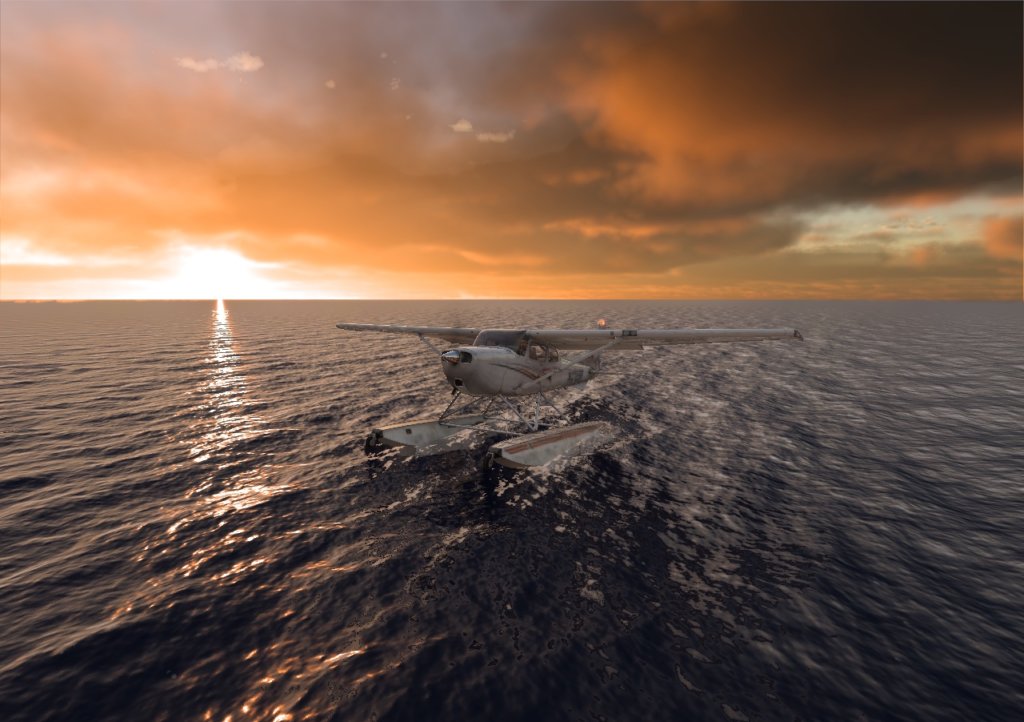
Now done with ALPHA-testing, here is an update for BETA-TESTING on the floatplane dynamics:
I’ve been working with Bridger Aerospace to get their fire-fighting seaplanes simulated, and the result is really incredible.
It took about FIFTY different alpha builds, each one with further-refined water dynamics, but we finally have the parasite drag, wave drag, plowing, step-taxiing, running on the step, wave interaction, and even drag from the scoops on the firefighters that grab water all simulated properly for Bridger to train their next generation of pilots! So the float-plane dynamics in X-Plane 12 are now professional-grade, for people that fly float-planes to put out fires for a living!
In addition to the dynamics of the floats themselves, we have better rendered wake, wind and wave correlation, and even docking with hard docks!
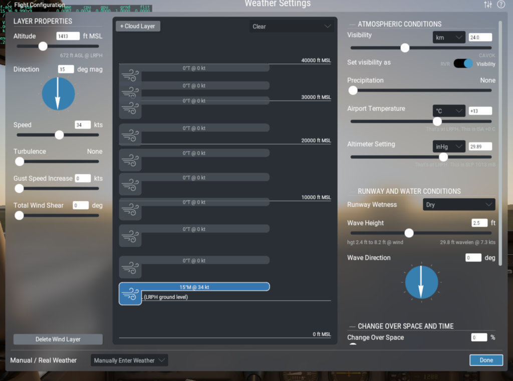
One subtlety is the new wave height paradigm:
Enter the wind and stuff, and look at the wave height slider: You see the range of heights as a little tip at the bottom, so you can drag the wave height slider accordingly for the conditions you want to fly…
Then, at right you see the little tip on the wavelength and speed that results from the height entered
We are doing first-principles with wave length and speed, and they match up with your chart pretty close, so I think we are good there
For real-weather, the wave height is auto-set to the SHELTERED case, based on the lowest-alt winds
So I think that has us where we want to be, with plenty of little notes there in the UI to show us what is going on… and give instructors the ability to set conditions as desired.. with the notes on the defaults available to them of course
Whew!
OK I like this paradigm a lot: Total flexibility, with super-easy normal-case references available at-a-glance.
Now done with ALPHA-testing, here is an update for BETA-TESTING on the tire rolling coefficient of friction data:
Observe these charts:

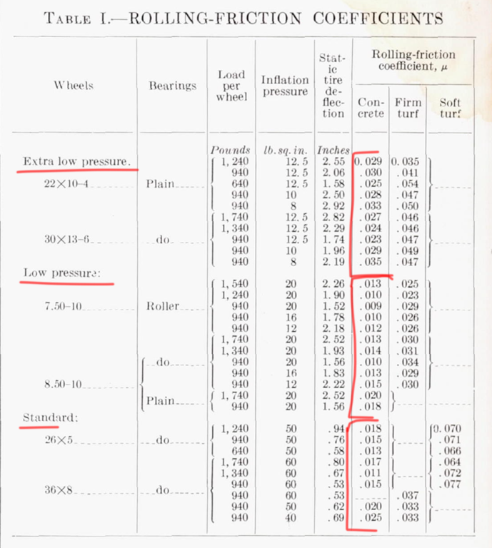 As you see above, rolling coeffs go from about 0.006 to 0.01 for high-pressure tires,
and 0.01 to 0.02 for more medium pressure tires.
So your planes should probably use 0.008 for the airliners and fighters,
And about 0.016 for the general aviation airplanes,
And about 0.040 for the piper.
Everyone that enters airplanes themselves should go to Plane-Maker and set tire coefficient of fric to about 0.008 for airliners to 0.01 for lower pressure airliners to 0.02 for light planes to 0.04 for very low pressure tires like the tundra tires on the Piper Cub.
Hydroplane speed more accurate, and on-wet friction a bit higher.
Now done with ALPHA-testing, here is an update for BETA-TESTING on the roll spoilers:
TECH NOTE for designers!
This is big: The spoiler effects were TOO WEAK in version 11.
This meant that in the sim, all the planes that used roll spoilers, which certainly includes airliners, rolled too slowly!
As a result, many people over-sized their spoilers to get the desired roll-rate… and got too much DRAG from those over-sized spoilers as a result!
Sigh.
This has now been fixed for X-Plane 12!
NOTE: Aircraft designers should now go into their aircraft and make sure that they have entered the correct sizes for their spoilers.. they should now get more-accurate results!
Now on to the initial report, done during alpha-testing:
Introduction
X-Plane 12 has been an interesting release because we had to rewrite… everything.
Here’s how it happened:
Ben started tracking watts per meter from the sun and stuff like that onto the material properties of whatever metal an airplane was made of, and the next thing you know our LIGHTING was based on the LAWS OF PHYSICS! OK, fine. This sounds like an interesting feature, but as soon as we did it, something suddenly became apparent: Compared to the excellent new airplane lighting, the airport PAVEMENT didn’t look right any more, by comparison. It just looked lame compared to the physics-based lighting on the airplanes. So we had to update our pavement. But then, compared to a sunny day, it didn’t look right when it was RAINING. All of a sudden, with all this accurate lighting, it suddenly looked wrong to have just flat-colored pavement when the rain was coming down: So we needed puddles. But that water looked SO WRONG when it was cold, so we had to have ice. But that did not look right when there was SNOW elsewhere: We had to have patches of SNOW on the pavement, but if we just had white, fluffy, fresh-fallen snow it would look wrong because we all know the snow on any airport ramp will be soon be plowed and what is left will be packed-down. And once we had all the packed snow and scraped ice and puddles, the artists started showing up with their next-gen ground vehicles, the art so incredible that you feel like you are looking at a real push-cart… until the cart didn’t STOP for a few moments to attach the tow-bar, which broke the illusion! So now the ground service trucks had to MOVE more realistically! And STOP between jobs. And so on and so forth. For Every. Single. Bit. of the Simulator.
You see where this is going. Every time we would do something RIGHT, it would make something ELSE in the sim look WRONG.
So THEN we would have to address THAT thing.
Which would make the NEXT thing stick out like a sore thumb.
And this has been going on FOR FIVE YEARS NOW.
By the time we were done, we had re-written every bit of the sim. While making sure that V11 airplanes and sceneries and plugins still worked! To get an idea of how much work was involved look at this document: This is the JUST the MAJOR highlights of JUST the flight model coded almost exclusively JUST by me… a TINY fraction of the total work done on X-Plane 12 by our team of 20 people or so!
So that’s what happened with X-Plane 12, and why it took so long to get out.
But the advantage to this is that we’ve overhauled… everything.
Everything in the sim has been brought up to a physics-based level, not just the flight model.
But the flight model is all I’ll talk about in THIS document, because that’s the part I did.
Before I get into the details, though, let me give you an interesting note:
It USED TO BE that we would record whatever the X-Plane flight model would do, and use that as a test-case for future flight model upgrades, to make sure I did not CHANGE ANYTHING and mess up everyones’ existing airplanes in the field. Now, though, for the first time, we are making test docs that are NOT based on PREVIOUS performance of X-Plane, but instead based on the ACTUAL Pilots Operating Handbooks, my personally-collected flight-dest data in N844X, Philipps personally-collected flight test data in a plethora of recip-engine airplanes, and YouTube videos (SO useful for showing jet-engine starts! Thanks, Dutch Pilot Girl!) that document exactly what the REAL airplanes do. So X-Plane 12 is the version where our reference document for testing stopped being PREVIOUS performance, and started being the performance of the REAL AIRPLANE. We’re now so close that our test-check is… REALITY. What really excites me about this, other than the realism of course, is that this means our test targets WILL NOT CHANGE ANY MORE! The target is reality, and reality is FIXED! When that’s the target you’re hitting, you’re dialed in, and won’t thrash between one build and another.
Another cool threshold has just been reached: For the last 25 years, there has been a SLIDER in X-Plane that you can use to ADD some ARTIFICIAL damping to make the airplane feel “less sensitive”. This is now GONE. The flight model is now so good that there is simply no need for it… if anyone STILL wants damping.. then they need to adjust their joystick or their flying skills! The flight model is now presented in a form that needs no post-processing to fly! The pure math works.
Clouds
Now, on to the details… We MUST start with the new weather system, including real-weather, because that’s the whole environment we operate in here:
When I first started coding X-Plane back in 1993, I envisioned three-dimensional, volumetric clouds in the simulator: Impossible at the time, of course, but it was my dream.
So I coded what I could: A bunch of two-dimensional ‘puffs’ of cloud and then Ben Supnik came along and made them way better by ‘bucketing’ them into a 3-D ‘scroller’ to give the best detail where needed but the whole thing still looked like 2-D posters of clouds. You got the impression you were in the film ‘The Truman Show’, the world always altering itself to present an illusion. For version 12, like every other system in X-Plane, it was time to up our game to physics-level. So how to do it? There was only one possible answer: Volumetric clouds. The premise was simple: The clouds must now be three-dimensional volumes, not a bunch of 2-D posters. It’s the only way they could work like the real clouds, so it’s what we have now in X-Plane 12. Just like our automated-test-targets are now REALITY, OPERATING around these 3-D volumetric clouds feels like FLYING in reality. So let’s look at that operation, and how it translates to the simulator:
When operating an actual light airplane we are, in many cases, highly incentivized to avoid cloud-entrance (illegality if VFR, icing, turbulence, possibly-fatal dis-orientation, possibly-fatal terrain-intersection, etc). Obviously, we have three options to avoid clouds in flight: Under, around and over. (The FOURTH dimension, TIME, is only comprehensible if you are willing to land and wait for entire system to leave the area).
Going UNDER the clouds seems feasible, until you get into really bad situations where the clouds get low… possibly lower than cell-phone towers and mountains, where terrain intersection can occur IN the clouds. So going UNDER is often NOT a thing you can do. I’ve tried this only once in my life, and it was the only time I was glad to still be in one piece when I landed, and questioning whether I really should have been flying at all.
Another option is to go AROUND clouds, but when they close in on you, wrapping around on all sides or standing in a huge line between you and your destination, this can become slow, tricky or even impossible.
The final option, of course, is going OVER the clouds. The thing is, they can go up so high and things get so BIG at this scale, that no matter how much you climb, the cloud tops may still wind up being above you. You can’t get above them. Soon, as you try to climb over the clouds, your aircraft can start running out of breath as it approaches its maximum altitude, with the cloud tops still dangling temptingly “just” above you. As an astronaut in the early space program once said, shortly after reaching orbit at about six million feet up: “Just a bit higher and I’ll be on top!”
So, the 3-D cloud-avoidance game is played at a rather huge scale, clouds dipping below, towering above and cascading off in all directions, possibly surrounding you and locking out your options to continue. Your aircraft has limits on going low for terrain intersection, going around for cloud distribution patterns, and going above for airspace or climb rate limits. And the whole thing, in addition to being huge, can get impossibly detailed, complex and 3-D, forming countless valleys, ridges, holes, openings, crags and other possible ways out that might just put you in an even worse position partway to the other side! And also it’s changing over time. Continuously. So it gets really complex to figure out your next move.
One of my goals with X-Plane 12 was to bring this type of operation and experience to the customer, and I think with our 3-D volumetric clouds, and our random change in weather over both space and time, we’ve done it. Now, trying to work through these volumetric clouds in X-Plane 12, for the first time, I’ve felt the same feeling in the simulator that I’ve felt in reality: Trying to work through a huge puzzle of ever-changing, pseudo-random cloud shapes in a tiny little airplane.
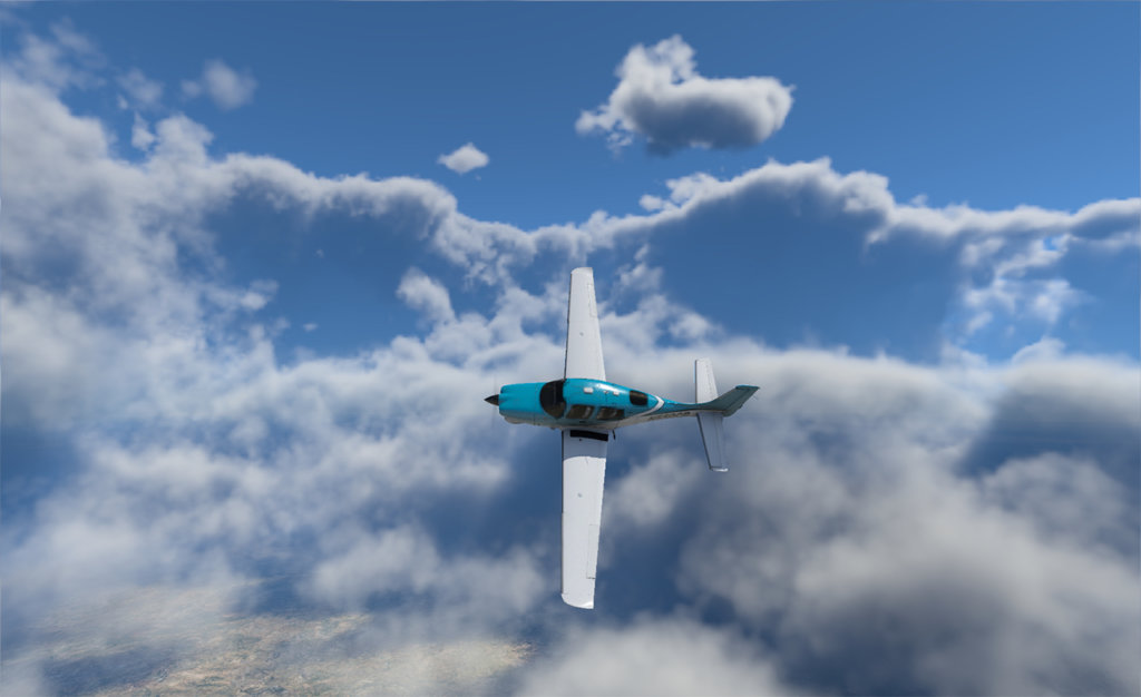
This is the view from high altitude… any little Cessna that tops out at 12,000 feet is going to be down IN that. Their options will be complex, and limited.

What is this guy supposed to DO right now???
To try this for yourself, got to the weather screen, same as always, but enter some RANDOMIZATION over both space and time! Then, X-Plane will use your weather-entry as a MEDIAN to putting weather all around the region of that approximate type, varying it randomly over distance! Enter a day with any clouds (especially broken stratus or cumulonimbus), and you’ll instantly see how the weather varies with space, leaving you places to climb or descend through the layer visually. The wind, visibility and barometric pressure will all vary with space in three dimensions. And then we add a fourth dimension: TIME. In the weather interface you can now set the conditions to slowly or rapidly improving or deteriorating, and the weather will of course change smoothly over time. Now, finally, with this four-dimensional weather interpolation, you can find yourself in that crazy game of 4-D chess with Mother Nature, trying to figure out how to get where you want to be without intersecting the clouds… or terrain.
Also, the time-lapse movies you can make with this rate of change of weather are simply epic. Give it a try! Set your airplane on the ground and go for a nice camera angle, with weather set to vary randomly over space and time… or just turn on real-weather! Set the X-Plane movie recording to 200x time-lapse and start the movie before you leave the computer for the day. What kind of movie do you have the next morning? Toss it onto YouTube! Maybe add a cool sound-track… it’s fun! OOOO! Turn on AI flies so the airplane is FLYING for this movie! Whuuuuut??? I’ve worked a ton on making the AI flies better, so you could in theory turn on AI flies for a 737 or my Evolution and start up a time laps move and then GO TO BED! Check out the time lapse movie 10 hours later and in theory that airplane will still be flying, having gone to lots of random airports! Does it work?
OK now go to the weather-settings page and note these new improvements in the UI that I made:
We now set cloud TYPE: Cirrus, Stratus, Cumulus, and Cumulonimbus (!) and all of that moves through to Ben Supnik’s excellent new renderer of course…The tops and bases sliders show the TOP in MSL, and the BASES in AGL… The airport elevation is shown clearly on the map, so you can see both the ground-level and sea-level cloud heights… Note the non-linear display scale, so a person could actually set some low bases, which was impossible with the linear scale… The wind handles are a constant, thin height that hints that they are interpolation points in space, not broad swaths of constant wind… The clouds show their type, coverage, bases in AGL, and tops in MSL, on each layer… Note that it’s impossible to drag the clouds too low or high, whether you drag on the tops, bases, handles, or mid-points, and unlimited cloud overlapping IS now allowed (!)… It’s impossible to drag the winds too low or high, and ordering from low to high selections IS enforced… The visibility is non-linear, finally allowing you to set everything from IFR to marginal VFR to 100 miles… The rain can only come from non-cirrus layers, since cirrus layers are made of ice crystals. So, a bunch of little things that happen when I get neck-deep into the weather system, which has been so, so fun to code!
Oh and be sure to set the weather to warm and set a bunch of water on the runway in the weather settings page and do some flying… the water effects are great!
Then set the weather to below freezing and set up some snow and ice on the runway! Cool! Now get in a jet and build up some speed on the runway and then reject the take-off at the last second… how’s you braking action?
So, that’s a little peek at the weather you SET, but what about the weather you DON’T set? That’s… REAL-WEATHER!
Real Weather
Okay, I coded every line of this one myself and I love this code. The real-weather we had in v11 was so “Meh” (2-D clouds, constant everywhere based on where you are now, so no visible change over space, and no smooth variation over time… bleh). But now, with the volumetric clouds we have to render weather with, how could we not overhaul the real-weather system to load them up with the best-possible data? Much like Tesla starting their first car with a Lotus and winding up with hardly a single part of the original car in their final product, hardly a single line of our version-11 weather code remains now. If something has to be perfect, you can’t just coast on whatever parts you happened to start with. So, let’s start with the requirements: The new real-weather system had to be global, accurate, available even far from airports that report weather, change smoothly over space, change smoothly over time, so there would be no sudden jumps or dis-continuities, and continue to function as well as possible even if some of the servers went down. Once I decided on this mission requirement, it was clear that basically every line of our old system was going into the trash and a whole new system would be created to replace it.
So here’s how it works:
First, we start off with a three-dimensional grid of data. This 3-D grid contains the terrain elevation, wind direction and speed, temperature offset from international standard atmosphere, dew point, visibility, cloud covers from various layers, cloud altitudes, clear-air turbulence and precipitation for every ‘cell’ in the grid. The size of the grid can be anything at all that I like: the code is so powerful and flexible I can easily make the grid just 1 degree latitude and longitude to just get the weather right near the aircraft, six degrees to get the weather in the scenery area you can see, or the whole planet to get the mother of all weather maps. I elected to make the region 90 degrees or so on a side, to get any quadrant of the planet you happen to be flying on the new weather map I made. This is big enough to get the (really) big picture but not too wasteful of RAM. Speaking of which, with a little clever understanding of simply the range of values that we can actually expect to encounter on planet Earth, each of the variables above is compressed to only one byte of RAM per cell, one-quarter of what you would expect if you know how much memory floating-point numbers usually take on computers! So now we have a nice big, easily re-sized, tightly compressed, three-dimensional grid of weather… cool!
Our FIRST job is to set it to international standard atmosphere as a starting-point, so that’s what we do.
Next, of course, is to fill it in with what’s currently happening, globally. Enter the National Oceanic and Atmospheric Administration (NOAA) Model Output Statistics (MOS) Gridded Binary (GRIB) file. Nothin’ like a fresh NOAA MOS GRIB! So the NOAA is constantly running super-computer-based weather simulations to predict what the weather will be at a global scale, in the near future. And they are constantly updating their predictions based on the latest observations. The weather patterns these computers come up with are quite accurate in many ways, and accurately show existing cloud patterns and hurricanes! And these models contain a 3D matrix of terrain elevation, wind direction and speed, temperature offset from international standard atmosphere, dew point, visibility, cloud covers, cloud altitudes, clear-air turbulence and precipitation for every ‘cell’ in their grid. Sound familiar? So, assuming the NOAA server is running (it usually is) X-Plane downloads those weather files (planet-wide, the only way the NOAA serves them) and loads up its’ internal weather grid with the GRIB data!
Viola! Now we have global real-weather, at an accuracy that is determined by a global computer forecast. So this is a good start and nice because it’s global in coverage, but it’s still not hyper-accurate. It’s just a computer forecast model, and we know that weather forecasts are far from perfect. And in this case, since the coverage is global, it’s still rather lo-res. Can we do better? Of course! The next thing X-Plane does is grab every reported Meteorological Aerodrome Report (METAR) in the world. You just KNOW I gotta supplement my NOAA MOS GRIBs with METARs! These are weather observations made at each airport. The advantage is clear: they are exactly right! The drawback is clear: We only have this weather at CERTAIN airports! So, X-Plane starts with the international standard atmosphere, upgrades that to the global GRIB data if available, and then upgrades THAT to the local METAR reports, wherever THEY are available! So, this is a three-stage weather load-up. All of this constitutes what I call a ‘moment’. It’s a moment in time. I store three moments. Why three? Simple: I have a moment representing the past, a moment representing the future, and a moment representing the distant future. As we fly, X-Plane smoothly interpolates between the past and future moments, giving weather that changes smoothly over time. And while this is happening, the distant-future moment is downloaded and scanned in the background. And when that scan is done, the distant future becomes the future, the future becomes the past, and the past is forgotten.. for a millisecond before that same memory is used to hold a new distant future! And the whole thing keeps running continuously: You should never see a hiccup in the simulation, because that distant-future moment should always be downloaded and scanned before it is needed for the time-interpolation.
So, we have a 3D real-weather grid that changes smoothly in space and time and an incredible volumetric cloud and first-principles lighting system to display it all, which is great but I want to geek out on the weather a bit more than just flying through it accurately… I want to see the math. So, to that end, I built a rather epic little weather map that uses an interesting fractal-type method of updating that causes the weather to render in ever-increasing detail over time. Check it out in the developer menu, and sorry about the little buttons in the lower-right to re-size and drag the window… that might be updated by the time you read this. So with real-weather ON, go to the developer menu to see my weather map. It has… more than a few things you can check out.
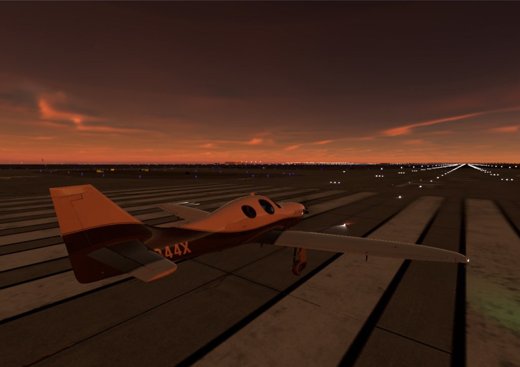
OK I just hopped into the sim with Real Weather ON to gab a screenshot and saw this… no need for me to look any further!
This captures the excitement and trepidation of an upcoming night flight.
OK so that’s a brief look at the WEATHER we fly in, but we’re not done yet! How the air MOVES is a foundation on which everything in a flight simulator rests, so let’s look at that next!
Thermals
Thermals: Our thermals are now connected to cumulus clouds, to make it possible for gliders to hunt them down.
The thermals go to the cloud tops, as they should.
And we have a really good ridge-lift model in here now, too.
Get in a glider and set a good strong wind in a direction you can remember, and then find some mountains running at a 90-degree angle to that wind.
Glide in ridge-lift on the up-side, slowly crash on the down-side!
Good for gliders, if you fly it right.
Oh also gliders have more realistic winching now, and also if you select the command for towplane left or right to a joystick button, you can HOLD the joystick button to get the towplane to turn left or right, and he should make a nice turn rate for you.
A few more notes on thermals:
The thermals now follow an accurate, localized profile, which looks like this:
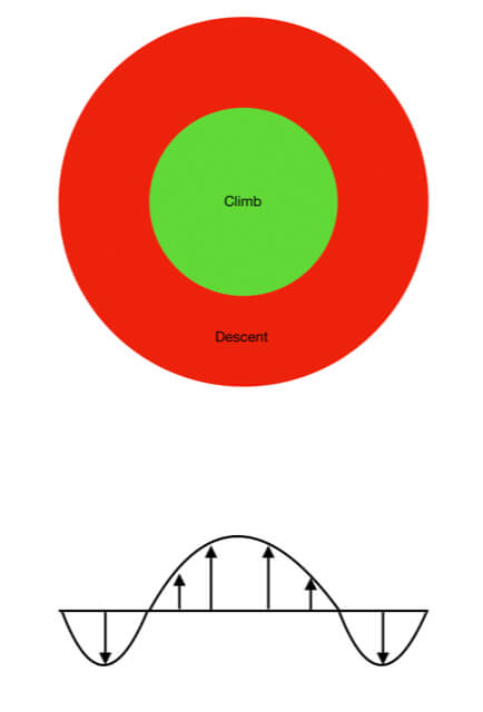
Also we can now select more thermal coverage and strength, but we will never find thermals above large bodies of water.
And boy oh boy have I gone round and round with Jan Vogel to get the thermals to be good presentations with real-weather on!
Now, with real-weather on, we get thermals that have been tuned based on cloud type, cloud cover, precipitation, wind, elevation, and of course time of day!
This tuning is based on countless rounds of tuning until Jan said it felt like what I see in flight.
Typical internal release-note from this process:
Now the thermals aren’t totally smothered by broken clouds.. now it takes overcast clouds to totally stop thermals… broken will just give… MOSTLY reduced thermals!
As well, CIRRUS clouds reduce thermals by, at most, only 25%, allowing 75% of the energy through, even in the overcast case! So Cirrus clouds only have 25% weighting factor for their coverage in reducing thermals.
Also, thermals START at 9 am and build up until noon, and then fade from 3 to 6 pm, so there is more time of day that allows thermals.
Also, the thermals fade out below 100 meters AGL, as per the ‘reverse-microburst’ effect.
Speaking of moving air, we also have new wake-turbulence model:
Get in the 737 at 15,000 ft and run it up to a high speed in LEVEL flight, external view, control-m until “wake turbulence” is shown. See the size of the vortices you are leaving? And their spin rate? That’s wake turbulence in action.
Now pull MAXIMUM G, a SEVERE, HI-G pull up… followed by a zero-g push-over, holding zero-g (and thus zero lift!) in the push over. What happens to the wake vortices over time? What are their spin rates and durations?
You can guess this when you know that the induced drag of the airplane, which goes with lift, is what is building the vortices.
OK now it’s time to have some fun:
Load up a few AI airplanes that are airliners.
Get in my Lancair Evolution and position yourself up above and just behind an airliner on the map.
Hit control-m a bunch of times until you get to “wake turbulence”.
Dive down on the airliner from above and enter is wake turbulence… close behind where it is red for a sharp jolt, or well behind where it’s turned green for a spinning ride.
None of these are fake forces! (Or forces at all, for that matter) These are all VELOCITIES that are being imparted to the AIR, and the all of the reactions that you get to this velocity are due entirely to rotating air mass left behind by the airliner interacting with the elements on your airplane! This has indeed happened to me in my real Evolution (by mistake of course!), so I’ve un-intentionally done this for real!
Microbursts
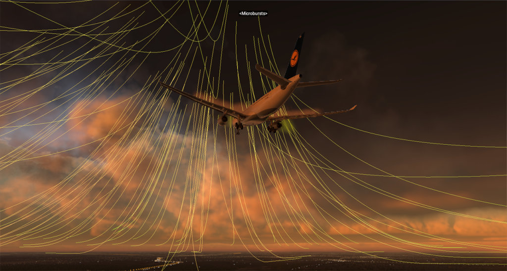
OK that was wake turbulence… now let’s try a MICROBURST.
Get in an AIRLINER at MAXIMUM GROSS WEIGHT.
Maybe the big bad A330.
Hit control-m until you get to the MICROBURST display.
Go to weather screen, set overcast and some rain.
Go to failures page.
The first failure page has “Microburst” on the right.
Hit that and then immediately take off from the “$” (Shift-4) view to see what is going on.
Can you get out of that in one piece?
See how the microburst STARTS as a headwind, then turns to a downdraft, and then finally to the worse thing of all: A sudden tailwind?
So we have a lot of fun stuff in the ways airplanes move through the air here… but how DENSE is the air?
That matters a lot, because that’s what drives how the air drives the plane!
The DENSITY is a result of the pressure and the temperature, so let’s talk about those:
Trying to track the temperature at AIRPORTS has NEVER worked well in X-Plane, because the temperature changes with altitude! Let’s say it’s 50 deg F… is that hot or cold? It depends on the airport! For a sea-level airports, it’s cold. For mountain airports, it’s hot! So entering the actual temperature at an airport doesn’t really tell you if it’s hot or cold… it depends on the airport! And when you look at aircraft performance in the operating handbook, they never list performance at absolute temperatures: They list the temperatures COMPARED TO INTERNATIONAL STANDARD ATMOSPHERE, or compared to ISA. The question isn’t how hot or cold it is, that always varies with altitude! The question is how hot or cold it is COMPARED TO STANDARD temperature. So now, in X-Plane 12, the temperature sliders show the offset from International Standard Atmosphere, or ISA, so you can see whether it is hotter or colder than NORMAL for that altitude, and check your pilots operating handbooks accordingly!
OK so we’ve established the new paradigm for X-Plane 12 for weather and moving air, so now let’s finally move on to the airplane.
Wings
We’ll start with the wings, which I’ve found to be very important:
The entire flight model is based on a new type of memory-access that is fast for the product you get, but slower and constantly self-checking for the internal builds we run for testing. We now have vectors of props, wings, and bodies… and access those vectors by accessors that hop right through to the memory for speed in the delivered sim, but do bounds-checking first to make sure no illegal accesses are even REQUESTED in our internal self-check builds. This entire new architecture, coded by me in the first month or so of the virus – when I could not even leave my house – sets us up with a platform that is flexible, fast, and bullet-proof to use. This new architecture allows for up to 16 engines and props, which is useful for the new generation of eVTOLs, many of which have more than 8 motors and props!
Now, for these wings and prop blades, we now allow THREE airfoil files per wing, not two like we used to, so you can have root, middle, and tip airfoils, which is especially useful for propellers! Well-modeled props have thick airfoil files at the root, mid airfoil files at the mid-span, and then go to a very thin foil right out at the tip to delay shock-wave formation at high speed. We now allow all the Reynolds numbers you like for each foil, so the way to get variation with Reynolds numbers is to put them in the airfoil files in Airfoil-Maker.. we don’t have multiple slots for different Reynolds numbers in Plane-Maker any more: that was always limited and awkward: It’s much better to save all your data for different Reynolds numbers for your airfoils in Airfoil-Maker, so that’s what we do now.
So everything you are about to read about is based on a new, high-speed, self-checking memory-layout that allows 16 engines and props, and 3 airfoils per flying surface.
First off: Wing sweep improvements. As air approaches a wing, it has to SPEED UP to get out of the way of the metal. It has to speed up to go around the wing! As a wing approaches the speed of sound, therefore, the air near the wing, (still speeding up!) must EXCEED the speed of sound to get out of the way of the wing fast enough! In other words, the air around the wing goes supersonic even when the wing itself is still below the speed of sound. This causes shock waves, huge drag, and even loss of lift. The thicker the wing, the more the air has to accelerate to get around it, and the greater this effect. Nobody wants all this extra drag as they fly at airliner speeds (which DO approach the speed of sound) so in World War 2 the Germans came up with a way to cheat: Sweep the wing!
When the wing is swept back, the airfoil SEEMS THINNER to the air. That means that the air is in less of a rush to get out of the way: That localized supersonic flow, and shock waves and drag that result, are delayed! You can go faster before you run into these shock waves. But here’s the thing: You can only cheat so much! No matter how swept the wing is, once your airplane is going Mach 1.00, you have fully supersonic flow over every bit of that wing: You can’t escape supersonic flow with wing sweep! Wing sweep only makes the wing seem THINNER, letting the air accelerate more gently to get around it, letting you get CLOSER to Mach 1.0 before you see supersonic flow over the wing! The thinnest, most highly-swept wing in the world will not AVOID supersonic flow, it will just let you get much CLOSER to Mach 1.0 before you get supersonic flow, and drag. X-Plane 12 now understands all of this, and invokes transonic drag at the right time based on wing-sweep, and transitions to fully supersonic flow by the time the aircraft Mach Number hits 1.0. It’s a nice interpolation from the subsonic to supersonic flow models as the flow goes from transonic to fully sonic on the wing! Back in X-Plane 11, the simulator delayed supersonic flow based on wing sweep until some value PAST Mach 1.0, which was erroneous! Forget that!
Alongside this drag-divergence understanding, which is critical to really dialing in that lift and drag, we now have updated Oswald efficiency, which is what turns lift inefficiencies into drag. Dialing in the Oswald efficiencies should make the induced drag more accurate. This is tuned based on the aspect ratio and taper ratio of the wing, stabilizer, or even prop blade in question, as we’ve gone from the simple old lifting-line theory to more experimentally-proven data.
As well, we I’ve something that I’ve thought of myself, that I’ve never seen coded or discussed before:
Everyone in aviation is always talking about induced drag and tip-losses, and you probably already know about this as well: The low pressure over the wing sucks air up from the bottom of the wing, around the wing-tip, creating a cyclone and causing drag. But here’s a subtlety people don’t talk about as much: What if you have a lot MORE INCIDENCE near your wing ROOT, and LESS near your wing TIP? It’s called wash-out, and it makes most of the lift in the CENTER of the wing, not the TIPS! If that low pressure is in near the CENTER of the wing, not out near the TIPS, then it’s harder for the high-pressure air UNDER the wing to find it’s way out to the wing-tips and then to the low-pressure region ABOVE it! BOOM. You just found a way to reduce induced drag. You cheated. By getting that lift into CENTER of the wing, far from the tips, so the air had FARTHER TO GO to make it from the underside of the wing to the top! A cheat. Nothing like a fair cheat.
Propellers, like it or not, get this BACKWARDS. They are moving so much FASTER at the TIP that they have their lift centroid pushed much farther out towards the TIP! As a result (sigh) they suffer much higher tip-losses, because the lift IS LOCATED out near the tip, making it exceptionally easy for the high pressure air UNDER the prop blade to sneak around the tip to the UPPER SURFACE of the blade, reducing lift and increasing drag in the process! A vortex is formed… and that energy lost! Here’s what it looks like:
But here’s an interesting thing: This problem of the pressure on the prop being centered near the TIP is mostly only a factor at LOW AIRCRAFT SPEED.
As the airplane speeds up (especially if they slow the propeller down) the speed across the prop starts to trend towards the overall speed of the airplane… then, the speed is not so concentrated at the TIPS any more!
So we see how wings can partially DEFEAT this induced drag (with washout), and props are subject to MORE of it (suction nearer the blade tips), especially at low aircraft speed and high prop RPM, but how do we SIMULATE this?
Well here’s what I’ve come up with: Each frame, X-Plane finds the CENTROID of all of the suction on each wing and prop blade. The centroid is WHERE the suction can be thought of as being CENTERED. This is surprisingly easy: It’s just a weighted average of all the suction on each element of each wing and prop blade! That’s not hard at all. It’s just a weighted average of the suction on each bit of the wing or prop. For a well-designed wing, that centroid will be INBOARD of the wing center by a bit, thanks to that wash-out. For a prop blade at high RPM and low aircraft speed, that centroid will be outboard quite a bit, close to the prop tip. For a prop blade at low RPM and a very high aircraft speed, the ENTIRE prop blade is moving fast, so that centroid will be outboard a BIT from the center, but only a bit. Now that we know where that lift centroid IS, we can add a simple little correction-factor to the classic rules on induced drag:
If the lift centroid is RIGHT IN THE CENTER of the wing, then the classic rules on induced drag apply.
If the lift centroid is EXACTLY AT THE ROOT of the wing, then the wing aspect ratio is EFFECTIVELY DOUBLED, since the air has twice as for to go to get to the tip.
If the lift centroid is EXACTLY AT THE TIP of the wing, then the wing aspect ratio is EFFECTIVELY ZERO, since the air is only moving right at the tip, where it flows right over to the other side!
…interpolate in between…
So, using this methodology that I thought up, I apply a correction factor to the aspect ratio based on WHERE the pressure is centered on the prop or the wing.
Now, in X-Plane 12, wing washout, prop efficiency gain from turning slow at a high aircraft speed… all of this is simulated. It’s some pretty nice math, in my opinion. I’ve never heard of anyone else doing it.
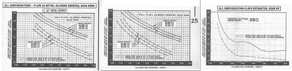
OK that’s transonic dynamics, wing sweep, and induced-drag corrections based on pressure-centroid location… next is delta wing dynamics! The F-4 Phantom has a delta wing, which really acts differently than a traditional wing planform. Defined as a leading edge sweep of about 45 to 75 degrees with a very low aspect ratio, delta wings are characterized by the air rolling up around the leading edge of the wing at high angle of attack, an easy proposition with all that sweep. With an unswept trailing edge, this exposes a huge wing area to a low pressure vortex at high-angle-of-attack flight, causing the wing to continue to put out epic amounts of lift, even at huge angles of attack that would stall any other wing! The air racing up around the highly swept leading edge in a controlled, continuous vortex, rather than breaking up into a chaotic stall, is the secret that lets planes like the F-4 pull huge angles of attack and get huge lift without stalling, and X-Plane 12 now understands all of this. Back in version 11, X-Plane didn’t understand the difference between a delta wing and any other wing, so it was not able to track this controlled vortex, and the huge lift it gives at large angles of attack. This new delta wing code in X-Plane 12 causes the F-4 Phantom to match the operating handbook and V-N diagram (lift-available vs speed) with rather uncanny accuracy. Working with an F-4 Phantom instructor pilot, we have this math dialed in. Here’s a few F-4 charts we now hit that depend on the delta wing effect, especially at high AOA:
Another pretty important thing is downwash: Downwash from the wing onto the stabilizer matters a lot because this is what sets up the TRIM for the entire airplane for any given angle of attack. Here is where it gets surprisingly involved: DOWNWASH determines STABILITY! Huh? Yep. Here’s how that happens: Say you are flying along at 0 degrees angle of attack, 5 degrees downwash onto the horizontal stabilizer. That means the tail of the plane is at NEGATIVE 5 degrees angle of attack. Now raise the nose of the plane. Of course that increase the angle of attack of the tail, causing the airplane to want to weathervane back to nose-level, which is what aircraft stability IS, but something ELSE is going on: As the nose comes UP, the DOWNWASH INCREASES, which pushes the tail DOWN, which, of course, brings the nose UP! In other words, raising the nose causes the nose to want to come UP MORE! THIS is the definition of INSTABILITY! So there you see it: DOWNWASH causes INSTABILITY, because the more you raise the nose, the more lift the wing makes, which causes downwash to INCREASE, which pushes the tail DOWN! DOWNWASH causes INSTABILITY. And the only way you are going to fly an airplane without an artificial stability system is if this downwash effect is SMALL ENOUGH to be overridden by the inherent stability of the tail weathervaning. So how strong is this downwash effect? The answer is critical to aircraft stability, and I’ve checked against a lot of charts to get it dialed in for X-Plane 12. The result is an ~25% or so increase in downwash compared to version 11. You should notice the planes have a bit more of a stable feel, and may need a little more nose-up trim for take-off.
A cool bit about downwash that it IS delayed from the wing to the tail… with the damping effect that that provides!
I’ve also tuned these downwashes a bit more for ground effect, and tuned the induced drag reduction and lift increase with ground effect as well.
This new ground effect code is great, and is fin to see in action.
On landing, for example, the reduction in wash from the wing to the horizontal stabilizer causes the stabilizer to go to a HIGHER angle of attack (LESS wash from the wing pushing it DOWN), so the nose sort of wants to flop down a bit… as in reality! Then, closer to the ground, the wing will GAIN lift, resisting touch-down somewhat. And, in ground effect, the wing will have LESS induced drag, causing the flare to last a while. All of these ground-effect impacts on the craft cause the landing flare and touch-down to be a bit different than just arresting a descent!
And that’s just for airplanes! We have ground effect for helicopters as well, where pressure waves bounce back from the ground right back into the rotor. And, as well, as you build speed, the ground effect will go away as the pressure waves coming down from the rotor wind up BEHIND you as you outrun them! But, no matter: Effective translational lift is stronger than ground effect, so if you can hover, then you can fly!
Flaps
New flaps and other control surfaces:
Another similar rewrite is to tune flaps and all other control surfaces. Flaps effect not only lift (which is what everyone talks about all the time) but also drag, and, critically, stalling angle of attack! So here’s what’s going on there: When you lower the the flaps, the lift increases. You already kew that. But here’s where it gets good: Lowering those flaps causes a SUCTION on the top of the wing! THAT’S where the lift COMES FROM! So what do you think that suction DOES? Give it some thought: That SUCTION up ABOVE the wing SUCKS THE AIR UP FROM BELOW! It SUCKS THE AIR UP OVER THE WING as the air approaches!
That means that air is coming UP as it approaches the wing from the front!! WHAT DO YOU CALL IT when that air is approaching the wing from the front at an INCREASING angle as it races up to the TOP of the wing? THAT is an INCREASE IN ANGLE OF ATTACK! YUP! Lowering the flaps INCREASES the angle of attack of the wing! Why do we care? Well, if the wing NORMALLY stalls at 16 degrees angle of attack, and lowering the flaps INDUCES 6 degrees angle of attack, then I got some news for you: YOUR WING WILL NOW STALL AT JUST 10 DEGREES ANGLE OF ATTACK! This is, um, worth knowing. As well, lowering the flaps really runs up that frontal area (more parasite drag!) and lift coefficient (more induced drag!) so the DRAG really comes up as well when you lower those flaps.
Since this stuff is not super-well documented, I did a good bit of test flying in N844X (my Evolution), carefully measuring clean and dirty stall angles of attack, descent rates with and without flaps, etc, to really get all of this dialed in. N844X is a great plane to do this because, with the gear up and the prop feathered, there is nothing there but a big wing and a sleek body: Nothing is getting in the way of a perfect test. So, with data from plenty of online sources and flight test data as well, we now have not just flap lift, but also drag and that critical change in stalling angle of attack. In Plane Maker, in the controls screen, look for that place that auto-enters the estimated coefficients of lift, drag, and moment every time you adjust your flap chord or deflections: Those numbers are all now based on flight-test. Just adjust your flap chord or deflections by a bit and then put them right back again to get Plane Maker to pop in the latest coefficients of lift, drag, and moment estimates. They should be more accurate than previous values in version 11.
Now, while we are talking about the flaps reducing stalling angle of attack, the same math is applied to all other control surfaces as well. You MAY know why this matters: AILERONS induce an angle of attack just like flaps, so lowering an AILERON will increase the angle of attack on that section of the wing! So, if you’re already near the stalling angle of attack and you lower an aileron, that section of the wing will stall! Here’s where this matters: Say you are in a plane at very high angle of attack, close to the stall. Then, you suddenly throw the stick full-RIGHT to try to turn RIGHT. The LEFT aileron lowers, of course. This induces an angle of attack, as previously discussed. This will stall the LEFT WING. And off the left you go in a stall. So that RIGHT turn you just commanded will not go according to plan when you just stalled the LEFT wing. Try to turn RIGHT: Enter a stall to the LEFT. Great. Then it gets better: Once the wing IS stalled, all the control effects are going to go down to just about nothing! Imagine a wing at 90 degrees angle of attack: What difference will it make what the aileron deflection is? Basically none. All of this is simulated in X-Plane 12, so now the flight control effects phase out as the wing goes to max angle of attack and then stalls, as per wind tunnel data that carefully measures and displays this data, and my flight test in 844X (where I measures stall angle of attack with flaps, not aileron deflection, to get safe, measurable, symmetrical stalls). So X-Plane 12 will not only INDUCE a stall from control deflection, but then cause that control effectiveness to be lost post-stall!
Bodies
OK we did wings… what about bodies?
We think of the bodies of airplanes as offering only drag, but they also put out some lift.
And some side-force if in a side-slip.
And here is an interesting thing: The aerodynamic center of a long, tapered body is about 25% of the way from the noes of the body to the tail, which is very near the FRONT of the body: Only 25% of the way back! This makes the body un-stable, wanting to flip around backwards. But if the body is rotated 90 degrees to the flow (90 degrees angle of attack or sideslip) then the aerodynamic center of the body is right in the MIDDLE of the body! So in other words, the aerodynamic center of the body shifts as the airplane changes angle of attack or sideslip! To visualize this, look at an MD-80 i cruise flight and it is obvious the fuselage forces are coming from way up front.. and look at an F-22 at a 90-degree angle of attack in a cobra maneuver and it is obvious that the fuselage forces are right in the CENTER of the airplane. You can see this in X-Plane as well: Get in the MD-80 in flight, hit command-m until you are seeing forces, and yank that nose WAY up: You will see the fuselage lift force building… and moving aft! Ditto that with side-slip, if the dihedral effect from the those swept wings doesn’t get you…
Trim
Speaking of deflected controls, let’s talk about trim.
Trim tabs control where a flight control RESTS, if you do NOT apply any FORCE to the stick to hold a given angle of attack. We don’t currently use sticks or yokes that move to different resting points based on trim settings in our home cockpit, so now we do the next best thing: Starting with X-Plane 12, the trim determines where the controls rest if you do NOT deflect your joystick. Then, when you DO move the joystick or yoke, FULL deflection of your joystick or yoke gives FULL deflection of the flight control as well. So the TRIM just sets your CENTER-POINT, and the stick can take the controls from that position to full deflection. Previous versions of X-Plane just sort added the trim to the total deflection, but this new trim model gets the control deflections done perfectly.
Oh and also dual-button aileron and rudder trim to go with trim-buttons for Honeycomb yokes, used on the real 737 for example…. we have that now as well, where you must it BOTH buttons at the same time to activate the trim, a useful safety feature in the real airplane, now simulated in X-Plane 12.
Philipp Ringler got into the trim system as well with his usual attention to detail in the systems:
X-Plane 12 now allows for three distinct ways of trimming the flight controls:
Aerodynamic trim, in which a little trim control surface is actuated by the trim.
This does not do anything at all when you are not moving, but once there is some airflow, it sets the flight control center-point.
Spring trim, in which the flight controls are pre-loaded to change the centering point.
The flight control moves to the new centering point even if no airflow over the control is present
Trim-able horizontal stabilizers, in which the center point of the elevator itself does not change, but rather the incidence of the whole stabilizer is changed, providing up or down force. OK, now back to Austin on the trim-able stabilizers:
I’ve changed the variable NAMES for these trims to:
flying_stab_trim_acf_nose_dn_abs_deg
flying_stab_trim_acf_nose_up_abs_deg
to indicate that they are magnitude of trim change, eliminating the confusion of the trailing-edge up/down terminology.
So we now have much better LABELS in Plane-Maker.
As well, STARTING with an aircraft that you SAVE in Plane-Maker, the flying stab trim will simply INTERPOLATE BETWEEN THE MIN AND MAX TRIM VALUES.
Min trim value nose-down 2, max value nose-up 14?
OK, then ZERO trim will be halfway between those: Nose-up 6 degrees!
This will let any artist simply enter ZERO for the element incidences on the stab, and enter the real, documented extrema for the stab trim in Plane-Maker.
And the trim will run a constant, un-changing speed through the whole range, even if it is 2 degrees on one side and 14 on the other.
And zero trim will be exactly halfway between the extrema.
This is clearly the way the system SHOULD have been designed in the first place, but I’m finally making it clear like this, um, now.
X-Plane 12 allows assigning different types of trim to different axes, so it is possible to have a trim tab on the elevator, but a pre-loaded centering spring on the rudder, as is common with many general aviation aircraft like the Cessna 182.
Helicopters
A lot of great stuff there for wings and flight controls… now lets do some HELICOPTERS, and get those ROTORS hooked up to some next-gen math!
Brett Sumpter has been testing the heck out of the v12 flight model for helicopters, and we have dialed that in as well. Let’s go through some interesting notes about the way they work, and just like the seaplanes: Everything I say applies to both the real airplane, and the simulation in X-Plane 12: Each sentence applies equally to both.
For a helicopter, in hover, it would be very easy to simply imagine the low pressure over the rotor blade because of course the rotor blade is a wing… But for helicopter flight that just isn’t the most informative way to look at what’s happening. For helicopters you need to understand the flow field of air into and around the rotor DISC. THAT is the thing that drives helicopter dynamics.
Let’s start with hover, in hover there’s a certain speed of air through the rotor as the rotor pumps air through. For every action there’s an equal and opposite reaction, and if the action is to accelerate air through the rotor disc as the rotor disc acts like a giant pump, then the reaction is to push the helicopter up to balance the air being accelerated down. It’s the action of the air going one-way and the reaction of the helicopter going the other. Fresh air must be found ABOVE the disc to be accelerated down towards the ground. But if you visualize this you see that there’s gonna be a major problem with how this works: Air is clearly going to be shoved out of the bottom of the disc and then sucked right back up to the top again! At that point you’re not accelerating the air so much as running it around and around in a circle. There’s no thrust to be had from simply running around in a circle over and over. You must grab fresh air and accelerate it down and then discard it. In hover, though, that air is not all discarded because a lot of it going to get sucked right around back to the top of the rotor. So you’re pumping some of the air around in a circle, just straight down. As a result, the lift is quite a bit lower. So in a helicopter, hovering actually requires MORE power than flying! It’s like trying to climb a rope ladder while someone is lowering the ladder down. Imagine this: You’re trying to climb up a rope ladder as someone else is lowering it. It’s awfully frustrating and uses a lot of energy and you’re still not getting anywhere. That’s the world a helicopter lives in as it hovers. The rotor is trying to generate lift in the air but that air that it is in is constantly coming down through the rotor. The rotor is effectively climbing up a ladder, where ladder is the airstream that’s being shoved down. Even though the helicopter is NOT MOVING as it hovers, if there is 20 knots of vertical airflow through the rotor disc due to this propwash, then the rotor is working as hard as if the helicopter was climbing at 20 knots straight up! That’s how fast the air is coming down, so that’s how fast the rotor has to climb up through it just to hold a hover. That’s a lot of work.
Now let’s say you get moving 20 or 30 knots or so… Now, all of a sudden, you are moving into clean, undisturbed air! So the rotor has unmoving air to grab! The rotor is now able to climb a rope ladder that is NOT being lowered down from above while the rotor is trying to climb it! All of a sudden, with this steady air not coming down from above, the rotor needs to do way less work to hold an altitude. This is called effective translational lift, and now at 30 knots the helicopter needs LESS power to fly than it needed in hover! Cool! Past effective translational lift, you are grabbing clean air and those rotors are starting to feel more like wings, advancing into clean, undisturbed air and using their lift to best effect, therefore requiring less power.
Now, keep speeding up, and things start to get awkward again. Let’s say your rotor tip is spinning around in circles at 400 miles per hour, and the helicopter itself is running forwards at 200 miles per hour: That rotor tip on the ADVANCING side (right side in the USA) is running forwards at clearly 600 miles per hour (forward speed of the helicopter plus spinny speed of the rotor), and at that speed, we are getting close to the speed of sound!
But who cares? HITTING the speed of sound generates shockwaves and huge noise and drag, and we are not HITTING the speed of sound, so who cares? WELLLLL… remember that the air has to SPEED UP to go AROUND THE BLADE (Bernoulli, you know) and if that air speeds up by 25% to go around the airfoil, then… BOOM. You just hit the speed of sound over the top of the rotor blade. That’s sonic. That’s shockwaves. That’s nothing but noise and drag. The ADVANCING BLADE (you know, the one going forwards as you fly) is running into the speed of sound and wasting all the power you could ever dump into it. So why not just spin the rotor SLOWER? You know, a nice BIG SLOW rotor so you don’t have that 400 miles per hour added to the helicopter speed on the advancing blade? Well, now let’s look at the RETREATING blade, the one coming AFT as the helicopter moves forward. The blades are spinning at 400 mp at the tip, the helo is moving forward at 200 mph, so the tip of the blade coming BACK is only going 200 mph! And, halfway out along the rotor blade where the spinning is only 200 miles per hour, the rotor speed on the retreating blade is literally precisely ZERO! That’s a stall no matter how big your blade! In other words, the RETREATING blade (the one coming backwards) is going so SLOW in the air that it is STALLING, while the ADVANCING blade (the one going forwards) is running into the speed of sound! These are both blockades! Impassable blockades! So you can’t go any faster. Period. That’s why helicopters are slow. And always will be.
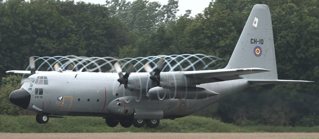
So you are flying as fast as you can at altitude and then the engine fails! Oh noes!

Flatten your collective prop pitch all the way to the floor (minimum setting) and as the helicopter settles, air coming up from underneath spins the rotor EXACTLY like a windmill! The helicopter rotor is now a PINWHEEL, being driven by air coming up from underneath.
The air driving the helicopter rotor is exactly like the air driving this pinwheel:

That’s how the rotor keeps spinning even without power… though you have to be descending, with the collective flatted to a negative rotor pitch, to keep that spin going! You CAN take this thing all the way to the ground and then suddenly increase pitch at the last second to land in one piece… it’s called autorotation.
BUUUUT let’s say your engine starts working all of a sudden, but is still at idle. You are coming down at some fairly low speed speed with power available. Let’s say you raise the nose to slow down to zero speed, and are settling vertically at zero forward speed, engine at idle. Air rushing up from below is spinning your rotor like a pinwheel. Now, you raise the collective and start feeding in power. Of course, the rotor starts shoving air down below it, creating propwash as we discussed earlier. What if the helicopter was descending at 20 knots vertically (so air is coming up from below, and into the rotor disc at 20 knots), and at the same time, your power input induces 20 knots of propwash, pushing 20 knots straight down, in the other direction? At that point the two cancel out and you have no airflow through the rotor. You’ve got no airflow to work with. Your rotor disc is like a parachute now: Something that is just STOPPING the air, no more. And that parachute is too small for a safe landing by far. So you fall. Remember, the only question a parachute asks is: “How FAST will we come down?”
This is settling with power, and at this point the air being shoved down below the rotor circulates right back up around the disc and into the top of the disc, forming a big vortex of air circulating AROUND the rotor disc. There’s no real THRUST here. Any helicopter will then settle rapidly, at rather scary vertical speeds, as the rotor does nothing more than pump air around in a big doughnut of circulating flow around the disc. There’s only one good way out of this: There’s only one good way out of this: GET MOVING LATERALLY! You can lower the nose and get moving forwards! If you are insane or about to run into a cliff, you can raise the nose and get moving backwards! Heck, roll off to the SIDE if you want! The only thing that matters is that you have to get OUT of that doughnut of circulating air that you created with your rotor! Get OUT of that doughnut of circulating air that you created with your rotor! As soon as you take your helicopter into clean, un-disturbed air, your rotor blades can start acting like wings again, and you can fly!
Another new thing for helicopters in X-Plane 12: BLADE SLAP! That SLAPPING sound you hear in helicopters when the conditions are right!
GET AWAY, WILL SMITH! YOU’RE NOT WELCOME HERE! THIS IS ABOUT ROTORS, NOT THE SLAPPING YOU’RE THINKING OF!
Flying a real helicopter, you really feel and hear a SLAPPING sound from the disc when you pull a bit of collective: The airplane is really talking to you, telling you that blades are GRABBING some dang AIR! But more precisely, what is going on here? In fact, each blade is hitting the VORTEX of the blade in front of it, so this only happens when both the vertical inflow UP FROM BELOW into the disc from the speed and angle of attack of the disc counter-acts the downwash DOWN FROM ABOVE through the disc so that air is NOT CLEARED FROM THE DISC!
Think about it: In HOVER, downwash is pumping air right through that disc… each blade is running into air where wake from the blade before has been pumped down and out of the way. Running forwards in cruise, if you suddenly raise the nose, then with that disc suddenly aimed up, air is rushing up into that disc FROM BELOW! If this upwash is counter-acted by the induced downwash, then the air is not really clearing the rotor disc, and each blade is hitting the vortex shed by the blade in front of it! SLAP! So blade slap only happens when the geometry of the situation shoves air up into the disc from below at about the same rate downwash is shoving it right back down, and and also the blades need to be at a high enough angle of attack to GENERATE the vortices for the next blade around to hit! Flying the wonderful EC-135 helicopter, with it’s turbine smoothness and resultant ability to really feel and hear the rotors, you really feel and hear that blade slap as you pull serious collective in the steep turns.
You can see this rotor slap as a data output now, and also here’s some datarefs if you are making your own helicopter and want to play some custom sounds:
“sim/flightmodel2/engines/rotor_disc_alpha_deg” (angle of attack of the rotor disc, after adding the influence of downwash through the disc)
“sim/flightmodel2/engines/rotor_blade_alpha_deg” (dynamic-pressure-weighted average of all element angles of attack)
“sim/flightmodel2/engines/rotor_blade_slap_rat”
As well, for helicopters, we have updated governors to CONTROL them, again from Philipp Ringler:
With no governor:
This corresponds to leaving the governor checkbox unchecked in X-Plane 11’s Plane Maker. The throttle will be fully manual. This is helpful if you want to code your own governor in a plugin.
With a Correlator:
The correlator is a linear collective to throttle linkage that automatically opens the throttle as collective input increases. In Plane Maker, you can set two control points to define the linear connection. The correlator is added after the throttle, and does not change the twist of the throttle grip. The correlator input is added to the throttle twist grip input whenever the throttle is out of detent, which by default is 5% throttle, but can be customized to your throttle hardware with a joystick control curve. By holding the throttle in detent (rolling it below 5% or the customized point on your hardware) it is possible to practice auto-rotations with the engine running.
With a Piston Governor:
The piston governor adds onto the throttle grip, so unlike the correlator the effect of the governor can be seen on the grip as the throttle will be twisted. When switched on, the governor will kick in once the throttle has been increased enough to go over 80% RPM. Because the governor adds to the correlator, the change in throttle grip caused by the governor will be relatively small, as big power changes are already absorbed by the correlator.
In case of governor failure, the governor fails in the current position, leaving the correlator intact, so it will require small adjustments by the pilot.
NOTE: To use this system, you must FIRST manually increase the throttle (f1/f2 keys) enough to get 80% RPM for the governor to engage!
With a Turbine Governor:
Unlike the piston governor, the turbine governor governs maximum RPM. The throttle twist grip works more like a condition lever, if the governor is operating normally. By twisting the throttle towards flight mode, maximum fuel flow will be enabled, but the actual fuel flow will be adjusted by the governor. This works without actually twisting the handle itself, so the throttle handle will show no feedback that the governor is operating, unlike in the piston variant. By blipping the rotor RPM trim, the governed RPM can be adjusted slightly.
In case of governor failure, the fuel flow restriction is removed, so the throttle in flight mode will most likely cause the rotor to overspeed. The pilot will need to reduce the throttle drastically to prevent that, and will then need to manually control the throttle to keep the rotor RPM in the desired range.
NOTE: To use this system, you must FIRST manually increase the throttle (f1/f2 keys) enough to get enough RPM for the governor to engage!
Helicopters are fun to fly, but we ALSO have incredible new 3-D rendered WATER, so it’s also time for… SEAPLANES!
Seaplanes
With our new 3-D water, the 3-D water RENDERING is exactly in sync with the 3-D water MATH, so our floats now interact fully with 3-D waves. Momentum-transfer, shear-friction, water-displacement at speed to clear the floats aft of the step, water rudders… we’ve got it all. Get i the 172 with floats, set the water waves to 2 feet high, and hit command-m a few times to see the forces…. you’ll see what’s involved here! With our Cessna 172 seaplane and new Robinson R-22 helicopter with floats (the “Mariner”), we get really excellent water interactions now. Fly both the 172 and the R-22 a bit on the water with some waves and you will really notice something: The Skyhawk MUST have VERY CAREFULLY shaped floats, very carefully operated to fly, because flight speed MUST BE OBTAINED on the floats! But the R-22? Meh. Couple of pieces of styrofoam would be fine. You just have to float since you operate vertically out of the water. Try both airplanes a bit in the sim now, with some good waves set: You’ll see what I mean.
Now, we took those water dynamics to a pretty darn high level for seaplane training! We’ve got some professional seaplane pilots on the internal test team and they are really helping me get it all dialed in. So here’s how seaplanes work: (Again, everything I am about to explain is how REAL seaplanes work, and is ALSO simulated in X-Plane 12: This discussion applies to both X-Plane and reality).
At zero speed, the floats work by simply displacing water… same as any stopped boat. The plane bobs in the waves like a cork. You already knew that. But here’s where things get interesting: Thanks to all the friction with the water, idle taxi speeds are on the order of ONE KNOT thanks to all the drag on those floats… and once you start building up some speed, the FRICTION between the floats and the water start getting really bad. In fact, in plenty of airplanes, if you’re holding the stick full aft to really keep your prop up high, the entire float will be in contact with the water, all dragging along and making huge waves… and you might not be able to exceed 20 knots! At full power! This is called PLOWING. The wave drag from the huge floats and friction with all that water is just too much. Remember, water is 800 times denser than air… 800 times!
Your floats are dragged to a standstill by the heavy water, but your prop has only the AIR to work with, at 1/800th the density of what the floats are in. That’s an uphill battle for the prop, so we need to find a way to cheat. And here’s what it is: It’s called the STEP. The STEP is a sudden step in the float, about halfway back, where the float surface suddenly recedes from the water. So for a take-off, once you get a bit of speed up, the water is willing to SEPARATE from the float at that step. Now that you have a little bit of speed and the water is separating from the float at the step, push the stick FORWARDS. Get the BACK of the float up OUT of the water. Now, only HALF the float is touching the water! Your friction area just got cut in half! At this point, you might be running 25 or 30 knots, airplane deck-angle level, the stick NOT held aft, the water separated from the float at the step, and the back half of the float held out of the water by the level (not nose-up!) attitude of the airplane. You are now running on the step, with only half your float even touching the water.
Now, as your speed builds, more of the floats come up out of the water. Soon, you are just water-skiing on the step, no wave drag since you are ON TOP of the water, not IN IT, and little friction drag, because little of the float is even touching the water! With the drag from the water on the floats now hugely reduced, you are basically running a self-propelled water ski, and any waves in the water are going to start to feel pretty “hard”. No more cork bobbing in the waves, water now has to be shoved aside at one THOUSAND kilograms per cubic meter (well over one TON per cubic yard!), and at 40 or 50 knots you are shoving that mass aside FAST. THIS is why the water seems so “hard” at this speed: Dipping even a few inches into it would displace thousands of pounds of water per second. If the floats can handle the waves, though, then this hard water is good for you, as it really pushes the floats up to the surface, minimizing the amount of the float that is IN the water, accruing friction drag.
As the speed builds, you really do NOT want to pull the nose up too much! Why? You don’t want to dip the back half of your floats down into the water! The DRAG would be huge! Use flaps or something for a nose-close-to-level lift-off: Not enough nose up to dip the back of your floats into the water and slow you down.
So that’s the takeoff.
On the way back down for landing, the reverse, but a few notes: A slower touchdown is good, touching the back of the floats first, for directional stability. Don’t touch the FRONT of the floats to the water: They may pull the plane to the side since your contact patch might be a bit forward of the center of gravity, and the drag might cause the plane to want to go nose-down a bit more than you may be comfortable with. So touch down slow, back half of the float down and grabbing water to trail behind you and keep you straight.. don’t worry about the high drag from burying your float: Slowing down is the whole thing about landing. The plane should slow down quick enough with all that friction from large contact area of the float with the water, and soon the water is not hard from skipping along it like a skipping stone, and you slow to the point you are bobbing in the waves like a cork again.
NOTE: GLASSY water is where there are no waves at all, the water is totally flat and smooth. This is HARDER to takeoff in, because waves are really convenient to break that water away from the float at the step! In perfectly smooth water, the water tends to stay STUCK to the float, making it harder to to get that water unstuck from the float at the step, and frankly anywhere else on the float. Your secret weapon here is to literally raise a SINGLE float up out of the water to cut your drag in half and accelerate more. This takes full aileron, and however much opposite rudder you need to run straight.
OK that was airplanes, which is great, but for fun we threw in a Robinson R-22 helicopter with floats as well! It’s called the “Mariner”, which may be a little bit of an aggressive name, because that machine is not super comfortable or maneuverable on the water: The floats have none of the careful shaping or step or anything else that the seaplane floats have: They’re just a pair of big old inner-tube balloons that will keep you from sinking… unless popped or something. Darn sharks! They don’t look good for more than 5 knots or so, so all your helo operations on the water in the R-22 will be vertical only… no running takeoffs or landings or anything like that.
Now I have to say that I’ve been doing a lot of seaplane flying in X-Plane 12, and it’s just plain fun. I always set a lot of waves and a high weight on the airplane, and then try to operate out of tight spots.
Gear and Tires
OK once you’ve done floatplanes for a bit, let’s get to something we THOUGHT was boring, but actually is not: TIRES!
(Funny side-note: I just took my Tesla Model 3 in to get a nail taken out of the tire, and the guy at the counter looked at the tires, then looked at mileage on the car, then looked at me with a blank expression: “We have NEVER seen tires this badly in need of replacement after only ten thousand miles. NEVER. We have literally NEVER seen such a case of tire abuse and wear.” My response: “No surprise! I’m always under a G of acceleration, a G of turning, or a G of braking!” Tire-guy: “Well now you’re in for a G of tire replacement cost!!!”)
So tires operate under harsher conditions then we give them credit for, and both the tires and their suspension is worth simulating well!
So here’s what we have: Check out the new custom tire/gear UI:
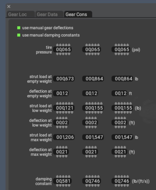
See the new info?
First, you enter the tire PRESSURE: Plane Maker uses this to estimate the load on each tire to start figuring out the ground attitude for the airplane.
Then you see, for reference, the strut load and deflection at the aircraft empty weight.
Then you enter TWO strut loads and deflections: A low weight and gross weight load and deflection.
If you want the gear to get really stiff at large deflections, the trick is to enter a low weight that is much less than the max weight, but still with a similar DEFLECTION!
That way, the gross weight deflection will only be a bit higher, but the load will be MUCH higher: That is a strut that gets stiffer at high deflections!
Or have the deflections proportional to the loads to have a smoother, linear strut resistance.
The NEXT thing I wanted to get right with gear was the incredible gear dynamics of the A330.
Here’s how that works:
The A330 has an Eagle-Claw landing gear system that is NOT just for looks: The AFT TIRE is indeed pushed down WITH THE FORCE OF THE MAIN STRUT, but thanks to the lever-arm of how it’s hooked in there (the “pitch trimmer”), when ONLY the AFT TIRE of the craft is in contact with the ground, there is maybe HALF the load on the gear per inch of deflection. You see, the pitch-trimmer bar is set up so that for each FOOT of aft tire compression as the plane lands, the main strut might only deflect HALF a foot, so the that aft tire is EASIER TO DEFLECT! This makes REALLY smooth landings possible: On touchdown, with the aft-tires-only in contact with the ground, the gear has only about half the stiffness of the fully-settled gear, making the gear feel really SOFT! Then, once the front tire is in ground contact, the pitch-trimmer bar goes SLACK! THIS is what’s so weird: Once BOTH tires are in contact, they each have the SAME LOAD on them, and the spring constant DOUBLES, because one foot of tire deflection is one foot of strut compression! So this pitch trimmer bar causes the first half or so of the gear deflection to be very soft as only the aft tire deflects, and then gets twice as stiff when both tires are settled… managing to keep the same weight on each tire! So super smooth landings should be possible! And, indeed, the last time I flew in an A330, I paid special attention to the landing, and sure enough: Settling that plane down was like getting into a soft lazy-boy chair: The initial contact was basically too soft to feel, and then force came up to a bit more of a solid feel as the plane settled. It worked perfectly: A smoother landing than any other airliner I’ve been in.
See the layout here:
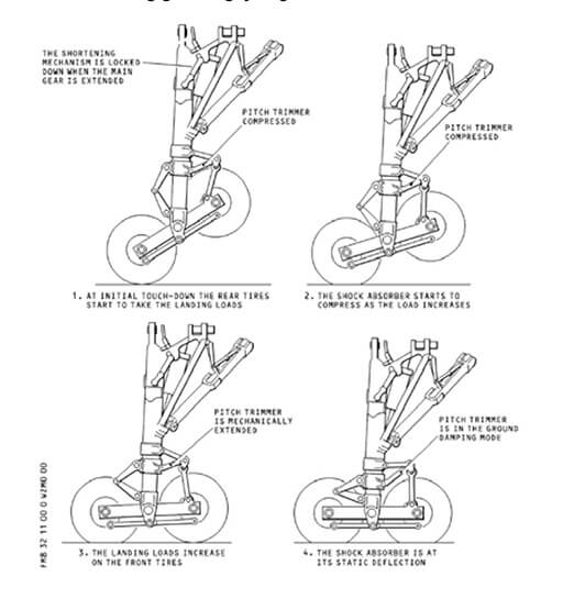
See that first frame? The gear force is really low there, and ditto that for the second frame, because a FOOT of TIRE deflection is only HALF A FOOT of STRUT COMPRESSION! Coming down to the bottom row, with all tires settled, the ‘pitch-trimmer’ is now out of the picture, and the full strut force is brought directly to bear on the airplane!
AND this gear design unlocks another secret: Lower TAKEOFF speed!
HUH????
Yep.
During take-off, as you raise the nose if you want a really short-field take-off, the lift from the wings is NOT YET ENOUGH to lift the airplane totally, but there IS enough lift from those wings to lift the airplane up onto it’s aft tires!!!!! That wing lift gets the airplane up onto it’s tippy-toes (frame 1 in the picture above). So the plane is standing on the AFT TIRE, and THAT means the airplane is sitting TALLER! TALLER! That lets you RAISE THE NOSE MORE WITHOUT STRIKING THE TAIL!
Yup. The plane sits taller on that extended aft tire, so you can raise the nose more without a tail-strike.
And THAT gives you the ability to get off the ground QUICKER in a pinch! A lower take-off speed!
I’m not kidding!
It looks like this:

Wait no sorry I mean it looks like this:
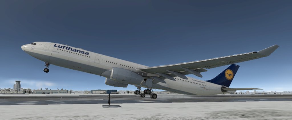
The A330 goes onto tippy-toes on the short field takeoff to raise it’s nose more without striking its’ tail!
TRY IT IN THE SIM!
If you try to raise the nose TOO SOON, it won’t work: The gear will stay FLAT! Not enough WING LIFT to go tippy-toes!
If you try to raise the nose TOO LATE, it won’t work: The plane will fly as soon as you raise the nose!
You have to bring up the nose at JUST THE RIGHT SPEED to see this work.
With the right trim for the CG of course!
Can you do it?
X-Plane 12 ain’t messing around: This is all first principles stuff: Do it in the sim and you could do it in the real airplane!
OK these vertical loads are all well and good, but one subtle issue is that the tires in X-Plane 11 always checked the terrain elevation at exactly ONE POINT on the ground, so any little stone or rock or imperfection on the ground wound up making your landing gear feel like this guys’:

But in REALITY, big tires can ABSORB bumps in the road, distributing load across a large number of pebbles or imperfections, smoothing out the ride.
For example flying the new Piper Cub we now have, with it’s mega-awesome TUNDRA TIRES, we spread out the contact patch over a larger area for a smoother ride.
C’mon: How do you look at this airplane and not want to take it off-road?
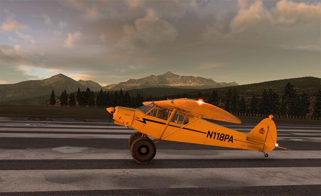
The TIRES in X-Plane 11 have always been POINT LOADS: The bottom of the tire footprint was tested against terrain to find the contact elevation.
But this was a BIT WRONG: It meant that when going over GRAVEL or other rough surfaces, the elevation of the ground under the tire kept CHANGING as it rolled over the uneven terrain! Does this SOUND correct? Well, it isn’t: Because with a big, huge, squishy tire, we don’t just care about the EXACT elevation right under the CENTER of the tire! No! We want the AVERAGE of ALL the terrain under that BIG, SQUISHY tire footprint! And, when taking that big AVERAGE, we get a MUCH SMOTHER RIDE! So, I just coded the tire model to find the AVERAGE terrain elevation within the (possibly huge) tire footprint, so all the gravel and sand and little bumps are all averaged and smoothed out by the big huge tires! So now, the bigger the tire, the bigger the footprint we average over for terrain elevation, and the smoother the ride over bumpy terrain.. just like the big tire on the real airplane! With this math, I finally understand WHY the bigger tire is better!
As well, I’ve put a bit more waviness in the runways… it’s always there in reality!
Whether in a little Cessna 152 or a million-pound A-380 (ESPECIALLY the million-pound A-380!) you can really feel the undulations in the runway in reality, so I’ve invoked that a it more in the sim here as well.
As well, be sure to enter the TIRE PRESSURE properly in Plane-Maker!
This is used to get the HYDROPLANE SPEED correct, which you can sure notice on a wet runway with standing water!
So the tire vertical forces from the struts, with awesome eagle-claw landing-gear for tippy-toe take-offs and lazy-boy landings, with distributed terrain interaction for a smooth ride on the comically-oversized Tundra-Tires is all great, but VERTICAL load is not the only thing we need to think about here: We also need steering! In Plane-Maker we now enter the transition speed from lo-speed to hi-speed tire steering limits, indicating when we like to stop using the tiller on various airplanes. In addition to vertical and side forces, I’ve upgraded the longitudinal force, which is…
Brakes
The NEXT thing we need to look at is something we got into at BETA as we used X-Plane to simulate ALIA (Google them): Brake Fade!
In reality, the brakes on any airplane are TINY compared to the total aircraft weight, so they are pushed to the absolute thermal limit on a max-effort stop.
And at Beta, as we flight tested ALIA first in X-Plane and then in reality, we wanted to be sure to get every detail in the sim perfect! And this includes how long the BRAKES can work for taxi, possible rejected-take-off, and landing. So now we simulate this: In Plane Maker, you can now enter the maximum SPEED TIMES WEIGHT that the brakes can absorb!
After that: Brake Fade! X-Plane carefully tracks that energy being soaked up by the brakes ANY TIME YOU USE THEM AT ALL. This includes taxi, DIFFERENTIAL BRAKES FOR TURNING… EVERYTHING. X-Plane won’t fail to notice every bit of braking you do. You can’t cheat the system. If you ride the brakes in taxi, or are rough with differential braking for turning, you will arrive AT THE RUNWAY with the brakes very possibly at or near their thermal limit, before you even start the take-off! If you then have a rejected take-off… well… you can’t always get you want. OR even what you need. Output the brake temperature ratio in data output, line 148, to SEE it as you taxi. When I coded this Brake Fade into the sim and first tested it, it felt EXACTLY like the Brake Fade I once had in a Corvette on the track… and once that happens to you once, where you are in a large machine, the brake pedal going to the floor, and the car not stopping… it’s one of those things where you NEVER forget the feeling of.
So that’s gear force overhauls or improvements in all three dimensions!
And we have updates to the anti-lock braking system, which is so dependent on the physical inputs to do it’s job properly!
Icing
OK so we have all these dynamics improvements on the wings and props and rotors, but that’s all for the perfect-day flight: What about what can happen in the real world, where you can start picking up ICE? Ice changes the AIRFOIL, so really: ice changes EVERYTHING.
I was recently called upon to use X-Plane in an accident investigation of a Lancair Evolution, and in doing so learned QUITE a bit about how ice effects aircraft, and I made sure to code it all in X-Plane accurately! Here’s the report in a Youtube video, which goes into this accident, how ice effects the performance of actual airfoils, and how I got that performance into X-Plane:
And here’s what I learned from doing this accident investigation:
THE MATH: WHAT ICE DOES
So let’s start with what makes airplanes fly: Coefficient of lift and Coefficient of drag.
Lift is equal to the coefficient of lift times the wing area times the air density times the airspeed squared divided by two.
Drag is equal to the coefficient of drag times the wing area times the air density times the airspeed squared divided by two.
Lift is equal to the lift coefficient times a bunch of stuff.
Drag is equal to the drag coefficient times a bunch of stuff.
As we know, we get more lift coefficient by raising the nose.
Now what does ice do to lift and drag?
All the aviation media in the world tells us that ice decreases lift and increases drag.
Too bad they’re all wrong, though…
For a given non-stalled angle of attack, ice does NOT reduce your lift much at all!
What ice really does is far, far, far more dangerous than that: It secretly lowers your stall angle of attack…a lot.
Then it makes it nearly impossible to recover from the stall that it just ambushed you with.
Here’s how I know:
Observe this report from Science Direct.
In this report, people carefully measured the effect of ice on lift and drag.
I show you some excerpts below.
DRAG is LEFT chart.
LIFT is the RIGHT chart.
X-axis is angle of attack, Y-axis is coefficient of drag on the left, and coefficient of lift on the right.
You can see the drag coefficients increase as ice is added to the wing.
I’ve colored that area yellow: For ALL flying angles of attack, as the ice builds, the drag increases… a lot.
You slow down. I colored the whole region is yellow: You are slowing down a lot with ice on the plane, with all that drag!
Now let’s look at the effect ice has on LIFT at right.
As you can see in the GREEN area (up to about 6 degrees AOA), ice has VERY LITTLE IMPACT ON YOUR LIFT!
It would be very, very easy to not even NOTICE it! The clean and iced wing have basically the same lift in the green region!
But look what happens when you get to an AOA of a mere 6 degrees with ridge ice: Your plane stalls!
That’s the red area. A stall at a much lower AOA than you thought possible. The red area is an area you can never safely access with ice on your plane… you invite a stall.
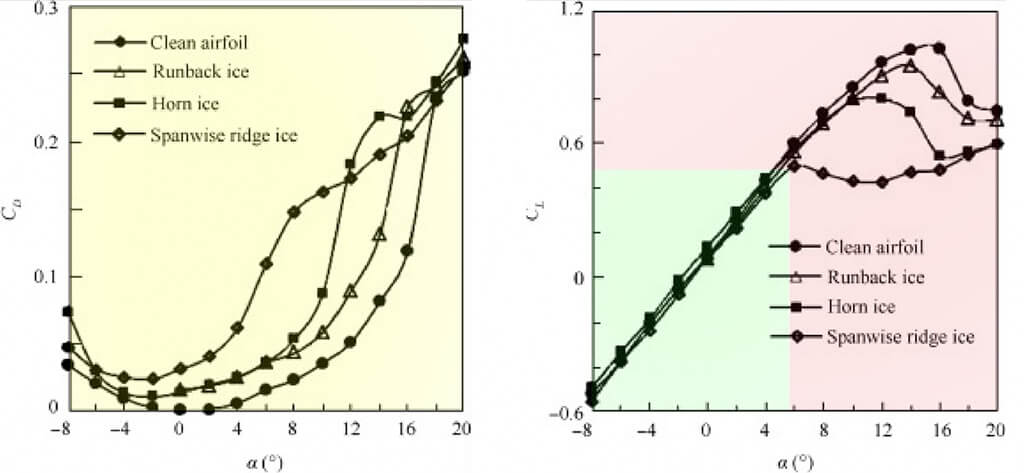
So let’s do some math on this.
All of my calculations below are based on a hypothetical flight scenario for N844X, my personal Lancair Evolution.
Stall AOA for N844X with a clean wing, if we use the lift chart above for reference: AOA 15 degrees, Cl 1.05.
Stall AOA for N844X with a ridge-iced wing, if we use the lift chart above for reference: AOA 6 degrees, Cl 0.45.
So with ridge ice, N844X will stall at at 6 degrees instead of 15 degrees… THAT’S LESS THAN HALF OF THE USUAL THE ANGLE OF ATTACK.
Specifically, N844X will stall at 6/15 = 0.40 = 40% of the usual angle of attack… a 60% reduction.
What does that equate to in knots?
I will show my work:
Cl when clean = 1.05 (normal typical max coefficient of lift, from the science direct article, shown in the chart above)
Cl when iced = 0.45 (iced max coefficient of lift from the science direct article, shown in the chart above)
k = one half times wing area times air density, a constant for any given moment in a flight in a given airplane.
lift when clean = 1.05 * square ( Vstall-clean ) * k (see my equation for lift at top of report to see where this comes from)
lift when iced = 0.45 * square ( Vstall-iced ) * k (see my equation for lift at top of report to see where this comes from)
We have the same lift in both cases, since we are holding the plane at altitude in both cases, so, lift when clean is equal to lift when iced: The autopilot sees to that by raising the nose!
So: (just running through the algebra so my work can be checked)
square ( Vstall-iced ) * 0.45 * k = square ( Vstall-clean ) * 1.05 * k
square ( Vstall-iced ) * 0.45 = square ( Vstall-clean ) * 1.05
square ( Vstall-iced ) = square ( Vstall-clean ) * 1.05 / 0.45
Vstall-iced = square root ( square ( Vstall-clean ) * 1.05 / 0.45 )
Vstall-iced = Vstall-clean * square root ( 1.05 / 0.45 )
Vstall-iced = Vstall-clean * 1.53
In other words, for the ridge ice case above,
IF the lift chart above is correct for a given airplane,
THEN you can take the clean stall speed of any airplane and add 53% to it: That will be your actual stall speed.
And THAT is assuming your WEIGHT never changed.
Of course, in reality, the WEIGHT of ice is also significant, and that runs up your stall speed as well as you carry more weight.
Starting with X-Plane 12, we now add ice MASS based on the SURFACE area of the airplane, following first-principles on ice density, aircraft surface area, and icing level currently on the airplane.
On a light plane, this can add up to 100 gallons, or 600 pounds, quite quickly in freezing rain.
APPLYING THE MATH TO N844X, MY LANCAIR EVOLUTION
The clean stall speed in my beloved N844X is 76 knots indicated.
So the stall speed with ridge ice is, without question if the chart above is correct:
76 * 1.53 = 116 knots indicated.
My stall speed with ridge ice is 116 knots indicated.
Higher than my calibrated white-arc stall speed.
Higher than my best rate of climb speed.
Higher than my best glide speed.
Higher than my AOA calibrated stall-warning speed.
Higher than my autopilot underspeed protection speed.
The stall speed with ridge ice is well within the speed range I would expect to safely operate the airplane.
The stall speed with ridge ice is higher than the speed I would use for stall recovery if I was stalled.
And if I fly AOA instead of speed, my stall is 6 degrees AOA when I expect it to be 15.
If I stalled, I might lower the nose to half the expected critical AOA: See the chart above: I would still be stalled.
If I stalled, I might lower the nose to best climb or glide speed to minimize drag: See the chart above: I would still be stalled.
My expected stall recovery procedures, aren’t.
GENERAL-CASE DISCUSSION OF WHAT A PILOT MIGHT THINK IN ICING SCENARIOS
So what might go through a pilot’s mind in icing scenarios?
Cruising along on autopilot, and ice is encountered. Remember, everyone teaches us that ice increases drag and reduces lift. This is not really true, though. As we see from our charts above, ice ads a huge amount of DRAG, but does not have too much effect on lift… at first. And in fact, lift does not degrade at ALL, because as ice builds when on autopilot… the autopilot simply keeps raising the nose to MAINTAIN LIFT!!
So when on autopilot, ice does NOT degrade lift.. the lift remains un-changed, because the lift impact is small, and the the autopilot even hides that from you by raising the nose!
Ice instead causes the airplane to SLOW and the autopilot raises the nose… with the stalling AOA cut in HALF!
You can see where this is going.
A slowing airplane with a gradually-rising nose and the stalling AOA being cut in half has an obvious and inevitable result:
The autopilot will fly the airplane right up to some angle at which the stall will happen.
But what about the pilot noticing the airplane is slowing down?
How could he? As the autopilot raises the nose to maintain level flight, the pilot is pushed back more and more in is seat… that feels like an ACCELERATION to me!!!
It feels like the plane is SPEEDING UP! He feels like the plane is going faster, not slower!
But what about the pilot noticing the airplane is slowing down with the airspeed indicator?
How could he? If the wing is iced over, the pitot tube could be as well, locking the indicated airspeed at the pre-iced value.
But what about autopilot underspeed protection?
It’s useless: The stall speed of an airplane with 90% of the ice demonstrated above is greater than the usual best GLIDE speed… certainly within the underspeed limit of any properly configured autopilot!
Who expects the stall speed to be above best glide speed?
But what about the pilot understanding the stall?
How could he? A pilot in that case is already known to be in IMC, and the PFDs we use are not really designed to show extreme attitudes.
But what about the pilot recovering from the stall?
How could he? He’s IMC, just taken over a stalled airplane, and the plane is now stalling at HALF the usual AOA, STALLING ABOVE BEST GLIDE speed… how could any trained stall recovery technique even APPLY here?
So we WRONGLY THOUGHT that:
Ice reduces lift.
(It doesn’t. It has little pre-stall effect on lift, and the autopilot raises the nose to hold altitude… the autopilot is literally maintaining an un-changing lift).
Autopilots keeping us from stalling with underspeed protection
(They don’t. Your stall speed is now much higher than we ourselves programmed into our autopilots).
We will recover by reducing AOA to less than 15 degrees or so.
(We won’t. We now stall at less than half the AOA we trained).
We will recover by increasing speed to well above stall speed under 1G.
(We won’t. Our stall speed is now above the best glide speed and the best rate of climb speed).
HYPOTHETICAL POSSIBLE CASE IN N844X, MY LANCAIR EVOLUTION, SOME DAY
Now, like I do every time I read an accident report, I will mentally put myself in this situation in my N844X, the Lancair Evolution you can fly in X-Plane now:
Some day in the future, maybe I’m flying along in the clouds.
Of course the autopilot is on, holding altitude with any pitch input required.
Of course 90% of my thinking is strategic, looking at weather, fuel, engine parameters, etc, not staring at the attitude indicator for subtle changes in pitch.
Ice starts to form on the airplane, which of course does NOT show on my avionics, which I am studiously observing.
The airplane slows from the huge drag, shown in the yellow region of the drag chart above.
As the plane slows, the autopilot does exactly what it’s supposed to: Raises the nose to hold altitude. Total lift remains equal to total aircraft weight.
As the nose comes up, I am pushed back in my seat more from the nose-high altitude: Feels like acceleration to me, not deceleration. I think we are going FAST!
At some point, the autopilot has me down to 116 knots (well above its’ 110 knot underspeed limit, so no underspeed limit is hit) and up to 6 degrees AOA.
The autopilot thinks there is no problem: I’m well above glide speed.
The AOA system thinks there is no problem: I’m well below the normal stall AOA.
The airspeed indicator thinks there is no problem: I’m well above stall speed, and even glide speed, and it may be iced over, showing the pre-iced speed!
The attitude indicator thinks there is no problem: My nose is up a little, but not nearly enough to worry about a stall with a clean wing.
But as you see from the charts above, at that point, I stall.
I’m in IMC at this point of course, since ice only forms in visible moisture.
The autopilot may keep pulling back on the stick, in the stall, thinking the speed and AOA are fine.
Pretend I’m so cool and collected that I turn the autopilot off and fly the stall recovery myself. I lower the nose to reduce angle of attack to 7.5 degrees… HALF my usual critical AOA.
No good. You know that my stall AOA is now 6 degrees.
I am so cool and collected I lower the nose to increase airspeed. I go to 110 knots, my best climb speed.
No good. You know my stall speed is now 116 knots. (and that’s assuming my normal weight at 1G… neither of which is true as I carry possibly tons of ice with rapidly-increasing speed and G-load).
I’m now in IMC, in a stalled airplane that I just grabbed from the autopilot, with G-load and speed building up in post-stall flight, perhaps with multiple stall recoveries and re-entries since the stall AOA is now so low.
At some point, the speed surely exceeds maneuvering speed, and I am perhaps pulling back on the stick trying to recover at an increasingly-high speed. No airframe can take that forever: At some point the G-limit is exceeded and the wing fails.
The post-flight observed result would be a constant-altitude parabolic speed loss on flight trackers and and an in-flight break-up.
These are some things I learned from investigating an accident, and all of this is coded into X-Plane, so you can try all of this in the sim.
Get in N844X, set conditions for maximum icing (in precip, just ABOVE freezing at your altitude) and give this a try… it’s all simulated.
Jet Engines
Alright, that’s a ton of info. Now lets look at something that is a bit more of a black-box in X-Plane: Jet engines!
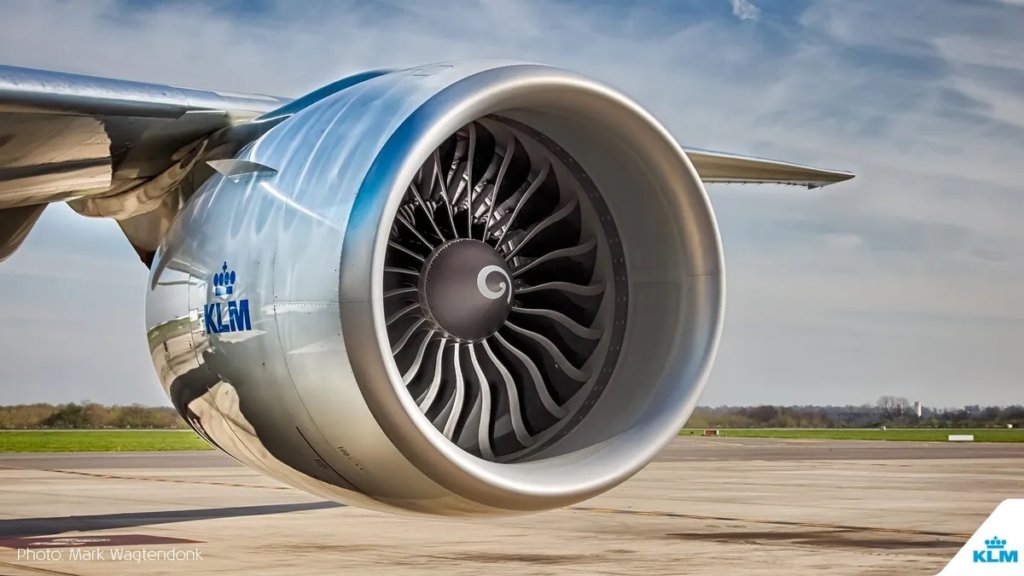
Another new item that is pretty large, in that it affects ALL jet airplanes, is the new jet engine fuel flow model. Back in X-Plane 11 I used to have low and high N1 and speed specific fuel consumption. This made little sense, though, because who’s going to fly at high speed with a low N1, and vice-versa? Airplanes don’t cruise that way, so you’ll never find the data to even fill those numbers in properly! That’s now fixed for version 12: We now enter the specific fuel consumption numbers for jet engine take-off, climb, low cruise, and high cruise! Finally, we enter numbers we can actually MEASURE in flight, and would actually want to USE! When you’ve entered all these numbers for SCF in Plane Maker, X-Plane uses a cool little algorithm to interpolate between the SFC numbers based on your flight conditions to give the most accurate weighted-average SFC for your current location in the flight envelope… because of course there is plenty of time in transitions between all of these modes! We now enter the afterburner SFC as well! And the time-requirement for the afterburner to ramp up to full thrust as well. I did a T-38 for training for the USAF and really got all these jet engine dynamics dialed in perfectly… they ran the T-38 though a bunch of flight test points I called for, with excellent on-board camera recording, and then I flew the exact same thing in X-Plane, literally matching their actual flight-test video in real-time. This let me get those high subsonic jet engine dynamics really dialed in well.
OK all this is great but now you have to understand a few things about how to set up the engines to USE this incredible new jet engine model!
For all aircraft authors, a note on terminology:
I have historically let you enter the “max” ITT, EGT, CHT, etc, for engine temperatures in Plane Maker.
Have you ever noticed the vague meaning of the word “max”?
These values have always been entered in Plane Maker right next to the place where you enter the ARC MARKINGS for the airplane.
But here’s the thing: Does MAX mean REDLINE?
There IS a “max” value to enter and there IS a “redline” value to enter… but shouldn’t they just be the same?
This has always been a vague point in X-Plane.
But now, with our new jet engine model, we clarify this:
The MAX temperature is the temperature at sea level, standard atmosphere, airplane not moving, 100% throttle, 100% N1.
Whatever temperature you get THERE, THAT is the MAX temperature.
Now here is the fascinating thing: The REDLINE needs to be HIGHER than that!
Why?
To give the engine some HEADROOM to dump in the fuel it needs to to GET to that state!
Remember, the temperature in a turbine engine is basically HEAT IN MINUS HEAT OUT!
HEAT IN is the fuel you dump in.
HEAT OUT is the heat carried away by the spinning turbine pushing hot air out the back.
So if the MAX temperature is 800 deg C at full throttle fuel in and 100% N1 hot air OUT, then you will actually go a bit ABOVE 800 deg C to GET to maximum thrust, because there will be a point where you have full fuel flow duping heat IN, but not yet full RPM carrying heat OUT!
So you need to enter a redline that’s a bit HIGHER than the max temperature so you can dump the fuel IN to speed up the engine, to build up the RPM to carry the heat OUT!
So now, to be clear:
The “redline” values you enter in Plane Maker are the documented redline values for the engine: Temperature to never exceed.
The “max” values you enter in Plane Maker are the values you get when the engine is steady at wide open throttle… very likely a bit LOWER than the redline to give some margin to accelerate TO max thrust.
This has always BEEN the case in the code, but bow I am documenting it officially: The “max” values may be tuned to lower values than redline so the engine does not over-temp when dumping full heat IN before the RPM has come up enough to carry full heat OUT.
I show the variables below. (Check out the all-new interface I made for Airfoil Maker and Plane Maker).
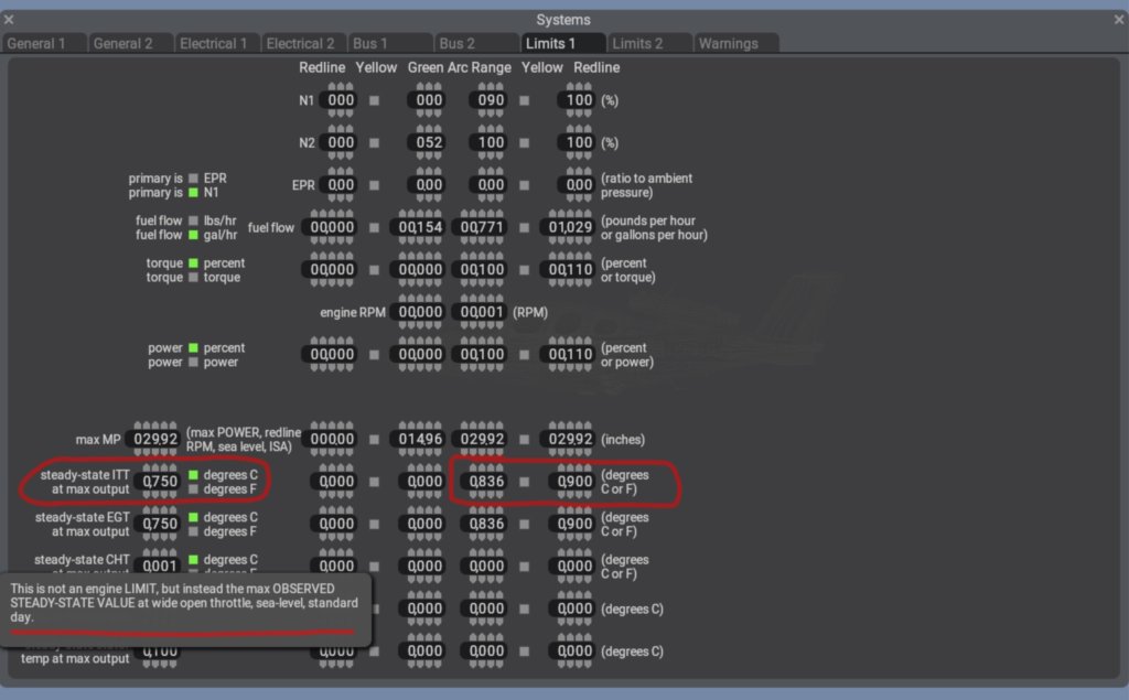
The new jet engine code is.. amazing.
See it here:
Oh wait wrong link…
Anyway: Tested and perfected in everything from the modern, high-bypass CFM-56 engines used in the Boeing 737-800 and Airbus A-320 to the 12-inch-wide, ZERO-bypass, “95% RPM or it ain’t running” YT-38 engines used in the T-38, this new engine model nails everything from start times, RPMs, and temperatures to shut-down times, RPMs, and temperatures, to RPM and EGT variation with Mach number from cooling air racing into the inlets to power-idle and power-off windmilling in flight at Mach 0.90… to the compressors turning on the ground in a 15-knot breeze on the ramp.
And you can control it all now, for your airplane, in Plane Maker, if you know how to ask for it.
And you can fly it all now in X-Plane 12, if you know what to look for.
OK let’s look at creating one of these jet engines now.
Launch Plane Maker.
Open the included 737 and let’s go through each jet engine setting in there, setting it as needed to dial in the CFM-56.
Go to the STANDARD menu, ENGINE SPECS item, ENGINES tab.
Upper left: First enter the flat-rated temperature if the engine puts out full thrust to some altitude, and then the maximum allowable thrust and burner thrust of course.
Maximum allowable thrust will happen at sea level, ISA, 100% N2, 100% N1, if the flat-rated temperature is 15 deg C.
Higher flat-rated temp will give you the same oomph at less than 100% N1, giving you the ability to go to higher N1 as you climb, keeping a steady thrust!
The fan RPM at 100% N1 matters! Sitting on the ground, engines off, in a 15-knot headwind, the engine will only windmill at a decent speed in the breeze if you enter the right RPM here! And airplanes that show compressors will only render properly if they turn at the right RPM! The CFM-56 is right at the edge of visual recognition of the swirl pattern drawn on the compressor nose at idle, and you can really tell the RPM from looking at it during start-up and shut-down, so be sure to get this RPM correct!
The compressor area is for jet wash and the reverser area for aerodynamic drag in thrust reverser deployment.
So both of those matter for sure.
Now go to the left side of the screen: Hi and lo engine idle adjustment.
This is the throttle setting for idle.
Set this to run the N2 (N2!!!) at the desired idle setting for your airplane.
We control N2, not N1, because the N2 DRIVES the N1, so everything starts with N2!
Entering 0.65 idles the N2 at 60% for me, which is just right for the CFM-56.
For your airplane, play with the idle ratio to get the N2 at idle that you want.
Lo and hi idle can be different if you like.
Enter whether we have a FADEC that prevents us from going over ITT, EGT, neither, or both!
Do this and the FADEC will limit fuel introduction to prevent exceeding these limits.
If you don’t check these boxes and if you firewall it, then full fuel will go in, even if there is not enough engine RPM to evacuate that heat!
Beware: Over-temp may result!
AND Philipp also got into next-level FADEC detail as well:
FADEC prevents over-boost below critical density altitude:
In the simplest setup, with just having the checkbox checked, X-Plane will simply limit the power output when the throttle is all the way forward. Maximum power/thrust will not be exceeded up to critical altitude or corresponding temperature, over which the power will gradually fall off. Remember, if your jet engines have a critical temperature above sea level ISA (15 deg C) or your power-engines have a critical altitude above sea-level (0 feet), then your engines can put out MORE than their maximum-allowable power at low altitudes and temperatures, so some sort of FADEC is needed to prevent over-boost, or YOU need to NOT push the throttle forwards enough to GET an over-boost, as is the case in N844X, for example.
FADEC target parameters:
Go to the “Boost and Controllers” settings for the engine over in the EXPERT menu and configure a thrust lever angle (TLA) expressed as a fraction of full throttle travel. For each thrust level angle (TLA) you can set the target N1 or EPR for the FADEC to hold. This is how Airbuses do it.
OK we have the thrust and how hot or high we can DELIVER that thrust, the idle setting for how fast we run the N2 at idle, and the compressor and reverser area for jet-wash and drag. Now let’s move on.
NEXT!

LOCATIONS tab: Put the engines where they go.
JETS 1 tab: Enter the power curve with which N2 drives N1.
Don’t know what to enter?
No problem!
Just enter 3.00 and you are close!
Or do even better: Set the little “TEST N2” button to the EXACT IDLE N2 OF THIS ENGINE…
and then tweak the power curve until the N1 label goes to the EXACT IDLE N1 OF THIS ENGINE!
SIMPLE!
Now you just entered the power curve that syncs them up perfectly, as the engine tells you at idle.
For the CFM, as you see, a power of 3.15 sets the N1 at 20% when the N2 is at 60%, which is EXACTLY how this engine idles.
If you only got 1 spool, then just set this to 1.0… there’s no difference between N1 and N2… they are the same thing!
This is fine.
NEXT!

JETS 2 tab.
Enter the power curve for THRUST with N2.
Just enter 2.0 if for the lower curve and 2.5 for the upper power curve, to simulate a high-bypass engine, or different numbers if you can find thrust versus N1 online for your airplane.
NEXT!

JETS 3 tab.
Enter the bypass ratio here: This matters for tolerance of high Mach number, windmilling… a few things like that.
Inlet compression efficiency tends to run around 95% or so, and this determines how efficiently the air is compressed by the INLET in flight.
If you seem to be getting too little or too much performance at high Mach numbers, adjust this inlet compression efficiency to give the engine more or less dense air.
Enter a normal shock Mach of maybe 0.80 or so for airliners with their big round inlets, and 1.00 or so for something like the T-38 with it’s razor-sharp inlet lips.
The big round inlet lips of the Boeing 737 and A-320 will clearly see the flow going supersonic to get around them coming through Mach 0.80 or a little more, so that normal shock Mach is down a bit lower than 1.00! If your airplane is one that can push Mach 0.85 or 0.90 or 0.95, then it probably has thinner inlet lips and a normal shock Mach very very close to its’ max speed. Loss of thrust will be very clearly shown in the data output screen of X-Plane, where you can output thrust to the cockpit display.
NEXT!

Now on the START/SPOOL tab.
JET TIMES section, in the middle:
Auto-start fuel engage N2 is the N2 at which the computer applies fuel during the engine start. 30% is the number for the CFM-56.
Below that is the MINIMUM N2 AT WHICH YOU COULD EVER ENGAGE THE FUEL, at which point the engine will IDLE AT REDLINE TEMPERATURE!
HUH????
OK here’s how it works:
Jet engines IDLE HOT because their turbines are working so bad down at low RPM that they cannot get that hot air OUT of the engine fast enough!
So jet engines can IDLE hot, because adding power might increase the FUEL by 50%, but increase the AIRFLOW through the engine by 100%, thus making the engine run COOLER as it speeds up! Yep! So they IDLE hot.
Then as you go to even HIGHER power, eventually the turbines are working fine but air starts piling up in there as more fuel is added and then the temperature finally comes up again near redline.
SO, this “MINIMUM FUEL-ENGAGE N2” is an indication of how SLOW your engine can run without over-heating! :-O
15% is a fine number to use, but:
If your idle temperature that you see in X-Plane is TOO LOW, then enter a HIGHER “MINIMUM FUEL-ENGAGE N2”, signaling that your engine MUST turn faster to clear out that hot air!
If your idle temperature that you see in X-Plane is TOO HIGH, then enter a LOWER “MINIMUM FUEL-ENGAGE N2”, signaling that your engine can keep itself cool even at LOW RPM!
Just think of it as an indication: How SLOW can I turn this engine and still move the heat OUT?! The slower you can get away with turning it, the lower your temperatures will be at IDLE! By tuning this minimum N2 for fuel into up or down a few percent, you can dial in your idle temperature perfectly, without question.
Over to the right of this is the engine-start fuel intro time.
Just watch the REAL engine start and measure the time from when the EGT FIRST STARTED TO RISE until the start-temperature PEAKED, and THAT is what you enter here: How long the computer takes to ramp up that fuel flow to full idle!
Below that is the fuel pump advance time: How long it takes for the fuel pump to speed up to full-bore.
You should probably just enter 1 second here (or less!) because the fuel pump is ABLE to spin up nearly instantly… even though the FADEC will doubtless reduce that fuel flow, and the engine will doubtless take a while to spin up thanks as well to inertia.
Speaking of which: Below that is the engine inertia. You can use the time required to go from 100% down to 50% N1 as a great reference here, and then tune this pursuant to flight-test in X-Plane, but the bottom line is that this is an indication of engine inertia. The larger the number you enter, the longer it will take the engine to spool down and up. 2.5 seconds is about what it is for the CFM-56, but if anyone can find me a video showing a pilot chopping power COMPLETELY at 100% N1 and doing nothing to at least 50% N1, then I can look at this to refine this a bit more.
Now to lower-left, starter torque ratio is how hard the starter can crank that N2.
(NOT N1! The starter does NOT touch N1! It cranks N2, which will then, if your airplane HAS a second spool, drag N1 up to speed).
Then the starter design RPM is how fast that engine can go with the starter still batting out max torque.
If the starter in the real airplane starts to loose its’ ‘oomph’ at 25% N2, for example, clearly slowing down the acceleration of the N2 during start, then 0.25 is the number to enter here. Above this N2, torque will go down as RPM comes up to hold a constant power. The starter is then power-limited, falling the torque down exactly as fast as the RPM comes up to hold a constant power.
NEXT!

And now for fuel flow: Let’s go to the SFC/SOUND tab.
Here, head on over to the right-most group and see the JET SFC window.
For each of take-off, climb, high cruise, and low cruise, enter the Mach Number, N1 (not N2!) and SFC.
The SFC is simply the fuel flow in pounds per hour divided by the thrust in pounds.
Simple.
Then, down at the bottom, if your fuel flow at IDLE is 6% of your fuel flow at FULL POWER, SEA LEVEL, NOT MOVING, then just enter 6% into the idle fuel flow fraction.
X-Plane will use that fuel flow at sea level idle, applying proportional changes along with air density, RAM air effect, inlet compression efficiency, etc.
And finally the afterburner SFC if you have that.
So the fuel flow is now quite straight forward to enter, and can give PERFECT results at the four datapoints entered, with interpolation in between, which will be pretty darn close.
NEXT!

STANDARD menu, SYSTEMS item, LIMITS 1 tab.
Now this one is important.
Here is the deal.
REAL jet engines dump in fuel to heat up and spin up their turbines.
REAL jet engines spin up their turbines to move air through them to cool them down.
BUUUUUUUUUT… how do they ADD fuel in the FIRST place, since the turbines must be spinning fast enough to move out the heat that the fuel generates????
And that is the limiting factor in how fast a jet engine can speed up.
At low RPM, the engine is not moving air through the engine fast enough to evacuate the heat, so it CAN NOT ADD VERY MUCH FUEL!!!!
But what if you want FULL THRUST?
Well, the computer can only add a LITTLE BUT of fuel to SPEED THE ENGINE UP A LITTLE BIT.
This will, in time, speed up the engine enough to bring in a bit MORE air.
Which will let the computer add a bit MORE fuel.
Which will, in time, speed up the engine enough to bring in a bit MORE air.
Which will let the computer add a bit MORE fuel.
Which will, in time, speed up the engine enough to bring in a bit MORE air.
Which will let the computer add a bit MORE fuel.
And so on until you eventually get to full thrust!
But if the computer added FULL THROTTLE AIR at IDLE RPM.. the engine would be melted, on the ramp, right now, guaranteed.
So the trick for the computer is to add as much fuel as it can.. without exceeding the engines ability to move that heat OUT!
So the computer adds fuel a bit more at a time as the engine speeds up.
And this takes time.
So, how MUCH fuel can you add NOW?
The answer to this question lies in the EXHAUST GAS TEMPERATURE LIMITS HIDDEN IN PLAIN SIGHT ON THIS SCREEN.
Enter the STEADY STATE EGT AT MAX OUTPUT.
If you are at sea level, standard day, not moving, 100% N1, 100% N2, then THIS is the exact temperature you will see.
But is that your REDLINE temperature?
NO WAY!!!!!
If it was, you would never be able to GET to 100% N1, because it always takes a bit HIGHER temperature to get to any power setting, because you always have to enter the FUEL FIRST… AND WAIT FOR THE ENGINE TO SPEED UP AND THE AIR TO BE VACATED SECOND!
So the engine will ALWAYS see a HIGHER temperature FIRST, as the fuel is dumped in but the engine is not yet sped up enough to vacate the heated air!
And THAT is why the REDLINE EGT must be HIGHER than the STEADY-STATE EGT… that is how the computer can afford to dump in some extra fuel to get the engine sped up!
AND FINALLY BRINGING IT ALL TOGETHER:
SO, when you want to make your jet engine:
FIRST: Enter the obvious stuff like thrust and flat-rating and compressor and reverser areas and RPM, all like you already know.
NEXT: ENGINES tab: Enter whatever IDLE ENGINE ADJUSTMENT gives you the right IDLE N2.
NEXT: JETS 1 tab: Enter whatever N2 POWER CURVE TO DRIVE N1 gives you JUST the right N1 at your idling N2.
NEXT: JETS 2 tab: Enter whatever N1 POWER CURVES give you just the right thrust with N1.
For a high-bypass engine, use 2.0 and 2.5 if you have no other data.
For a zero-bypass engine, use 5.5 and 5.5 if you have no other data… those little engine s need to spin FAST to do ANYTHING!
NEXT: JETS 3 tab: Enter the bypass ratio, compression efficiency of the inlet to give you the oomph you want at hi-altitude (and thus hi-Mach-number) cruise, and the normal shock to tell you what Mach number the party is def over. Almost certainly the MMo of the airplane, because why design the inlet to do anything else???
NEXT: START/SPOOL tab: Enter the AUTO-START FUEL ENGAGE that the real airplane calls for (prolly about 30%), and the MINIMUM FUEL ENGAGE (prolly about 15%) as needed TO HIT YOUR IDLE TEMPERATURE TARGET. IF YOU ARE IDLING TOO HOT, THEN LOWER THIS NUMBER TO SIGNAL THAT YOUR ENGINE CAN ACCEPT A LOW RPM WITHOUT OVER-HEATING! IF YOU ARE IDLING TOO COLD, THEN RAISE THIS NUMBER TO SIGNAL THAT THE ENGINE HAS TO TURN FAST JUST TO KEEP FROM MELTING!
Then enter the engine start fuel intro time to track the time required for the EGT to go from zero to peak during an engine start: That’s how long the computer is taking to ramp up the fuel, for sure.
The enter a fuel pump advance time of maybe 1 second… or less.
Then enter the turbine inertia: The time required to drop the RPM from 100% to 50%… a bigger number to slow down slower, since this is inertia measured as time required to cut RPM in half from 100%, where the aero loads on the compressor are greatest.
NEXT: SYSTEMS window, LIMITS 1 tab: Enter the steady state EGT to hit your EGT target at 100% N1 and N2, motionless at sea-level, and then make sure the redline is HIGHER than that, so the computer can dump in a bit of extra fuel to GET UP TO THAT 100% IN THE FIRST PLACE!
So, there you have it: Jet engine entry in Plane Maker.
Now let’s fly it in X-Plane and see how it flies.
Hop into X-Plane and open the 737.
Set the weather to default CLEAR to get rid of any wind, which will affect results for sure.
You are on the ramp engines running, if you start with engines running.
Let it idle for a bit to warm up the engine itself.
Now check out this video:
https://youtu.be/zjFATiN4mJU?t=7
Turn the engines to OFF at the exact moment they you see the N2 start to come down in the video.
Compare what happens in X-Plane to that video.
Watch the N1, N2, EGT, and fuel flow.
Wait the full video length to get that N2 and N2 down to less than 1%.
Note how in X-Plane the EGT comes DOWN as some cool air is being swept through the engines by the coasting turbines, then comes up again as the turbines stop.
Yowza.
Now set the WIND to 25 knots or so, pointing right AT the airplane.
That 25 knots is AT THE WINDSOCK ELEVATION.. it’s 15 to 20 knots or so at the airplane.
Watch the N1 idle… 1% is just over 50 rpm: 1 rotation per second.
Yowza.
Now watch this video:
Hit the starter under the engine gages exactly when she does, and let go of the starter at exactly 55% N1.
Compare what happens in X-Plane to that video.
Watch the N1, N2, EGT, and fuel flow.
Yowza.
Now get in the air and on approach to a sea-level airport all dirty at 130 knots or so.
Now watch this:
Established at 55% N1 and watch his missed approach, specifically how quick his engines, and EGT, respond to instant throttle input.
And look at the N1 and EGT for… THE ENTIRE FLIGHT.
Compare what happens in that video to X-Plane.
Yowza.
The real 737 cruises at:
N2 of 92%
N1 of 87%
37,000 ft.
Here, it sees 615 EGT.
Compare that to X-Plane.
Yowza.
When done with cruise, yank power and descend.
Set the throttle open JUUUUST a hair to hold about 70% N1, 33% N1.
The real airplane runs 245 EGT in that case, cool air racing through cutting the EGT in HALF from idle motionless, on the ground.
Compare that to X-Plane.
Yowza.
And I’ve done all this, and more, in the T-38 as well for the Air Force.
Now, if you make jet planes, go do the engine for YOUR airplane!
OK we got the jet engine simulated and entered, but what about the AIR that that engine kicks back over the airplane?
One REALLY fun one for me to overhaul has been jet-wash, prop-wash, and entrained flow. This was done while building and flying an updated F-4 in X-Plane 12, flight testing it daily with a real F-4 Phantom instructor. Building the F-4 Phantom with Huss, we found that the REAL airplane was able to raise the nose in the take-off roll about 10 or 15 knots sooner than the model we were simulating in X-Plane. WHY? We checked that center of gravity and landing gear location and engine mounting geometry so many times.. and the delta-wing effect on the horizontal stabilizer 😉 … yet our nose gear always came up about about 10 or 15 knots too fast in the take-off roll! WHY? I asked Huss to prove how jet wash might interact with the stabilizer in the F-4 in desperation (Because it must NOT, right? And how would Huss know if it DID?) And he shocked the hell out of me: He had a diagram showing… where ground crew must NOT go behind and F-4 Phantom with the engine running! Perfectly diagrammed and dimensioned and labelled, this diagram showed jet-wash speeds and temperatures for the entire exhaust plume behind an F-4 Phantom running at full throttle! BINGO!!!!!!! AMAZING! All of the data on exactly how the jet wash of the engines GRABS the local air and SPEEDS IT UP (ENTRAINS IT!) was presented in a perfectly-mapped diagram. It was one of those moments where everything you thought was impossible to know is suddenly presented to you on a silver platter.
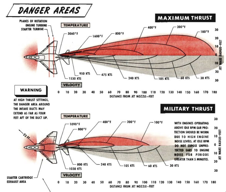
As soon as I coded our findings, an extra 10 or 15 knots or so of entrained flow was dragged over the horizontal stabilizers from the jet-wash, and the nose-gear on the F-4 popped up at exactly the right time in the take-off roll. BINGO. (Version 11 never had any inkling of this entrained flow… it would just assume that the jetwash has no impact on any flying surface).
Now, overhauling jetwash the entrained flow that goes with it, I went on ahead and took it to it’s logical extreme and over-hauled the propwash as well. Propwash is sort of different than people think: For a plane not moving, the air is SUCKED INTO the prop disc from the front, pressurized, and then CONTINUES TO ACCELERATE EVEN WHEN AFT OF THE PROP. In fact, only HALF the propwash speed is actually realized AT the prop disc! So if the propwash is 50 knots behind a parked airplane with the engine running at run-up power, then the wash is only 25 knots AT the prop disc!
As well, if the thrust of the prop is, say, 500 pounds at this point, generating 50 knots of propwash, then for the same airplane, still generating 500 pounds of thrust in cruise, the propwash may only be 5 knots or so! Yep! The faster you go, the lower the propwash.
So its like this, for a given airplane with, say, 500 pounds of thrust:
GROUND: Thrust 500 pounds. Airplane speed 0. Propwash speed 50 kt. Total speed in wash: 50 kt
CRUISE: Thrust 500 pounds. Airplane speed 200. Propwash speed 5 kt. Total speed in wash: 205 kt
So the propwash velocity vector follows an S-shape, when seen from the side, where the x-axis is the distance to and past the prop, and the y-axis is the propwash speed. The air is sucked a bit up to the prop at first, then really accelerates suddenly, reaching half the propwash speed at the prop disc, then accelerates rapidly right behind the prop in all that pressure, then accelerates more slowly over distance moving aft. An S-curve. Also the air is rotating in a helix as well. Get in my Lancair Evolution on the ground, maybe add a little power, and hit COMMAND-M a few times! You will SEE the propwash and helical spiraling flow.. its all there! This is super-fun in a Lancair, where the spiraling propwash becomes the dominant actor on the airplane at high power and low speed, but this really gets fun when you have co-axial, counter-rotating props! Try making such a helicopter in Plane Maker! Indeed, the propwash will be two overlapping S-curves, each prop feeding off the flow of the other! The lower prop, clearly, is in SOMEWHAT higher wash, but the UPPER prop is still in SOME wash from the LOWER ONE! Yah, I think I got the math correct on this one! Be sure to go to the data output screen and look at the propwash and prop efficiency in some prop planes to see how these numbers run. A fun one to look at is the DISC CD! What’s that? Well, this is a data output that says that IF the prop disc was a SOLID DISC, what drag coefficient would it have? For example, if the CD was 0.0, then that means the prop disc has no thrust or drag: The thrust must be zero. If the disc coefficient of drag was 1.00, that would mean the prop disc brings the air to a perfect stop, no more and no less. So now, for the windmilling prop in flight, it’s interesting to see how much drag your disc has.
Let’s take a look at a bit of propwash and downwash in flight:
We’ll start with an easy one: Spiraling propwash, and you can see the air is getting sucked into the prop, with SOME wash correctly in FRONT of the prop!
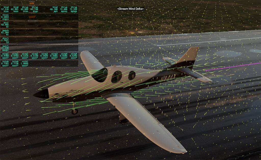
A little more complex: Can you see the downwash from the flaps on the wings, and the decelerated (red) flow near the body?
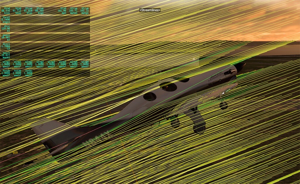
Let’s kick it up a notch with Beta’s (real!) ALIA: Se the wash from the four big lifters and the one pusher?
See the spiral nature of the flow?
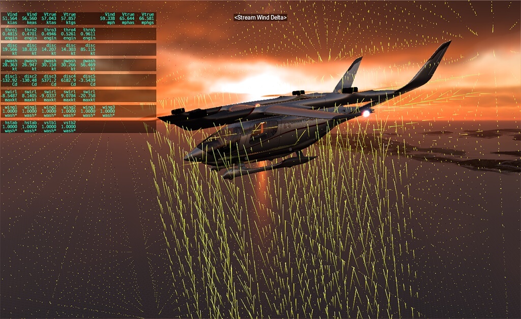
Now we get moving forwards.. wing wash is now built in there, and streamlines are effected by all parts of the airplane…
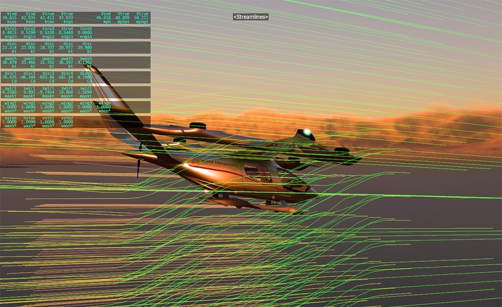
And now the ENTRAINED flow: Sure, the wash as we add power is 60 knots in the core, but a few knots are dragged along even far from the engine core!
This is based on math that came from the F-4 Phantom entrainment map. (The A330 has much larger, but slower flow of course).
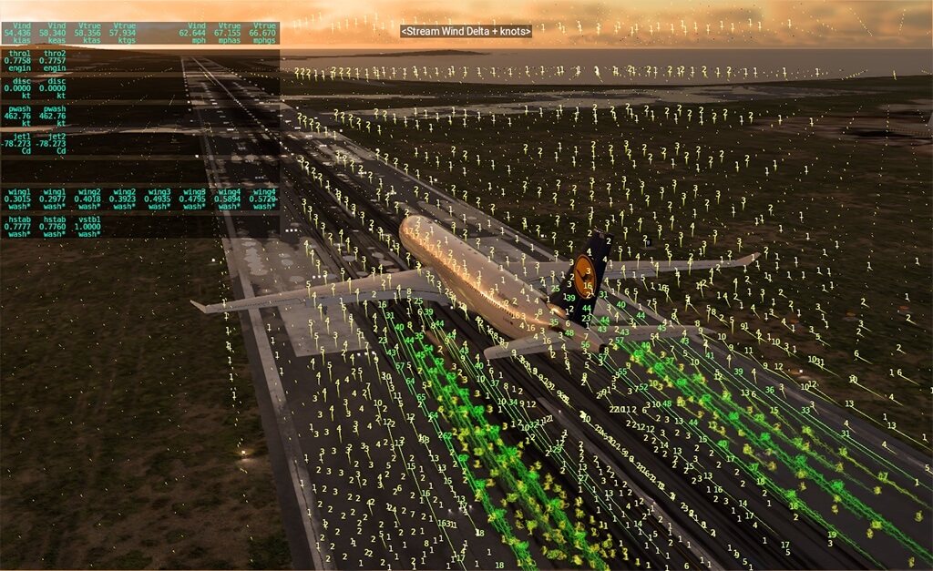
So the jets….
Another pretty big one that does not seem super-important to me somehow for the F-4 and F-14, but is really important for the civilian jets, is the jet engine START. Having watched tons, and then more, and after that some more YouTube videos of every type of jet engine start I can find, it’s safe to say that our 737 and A-320 have engine starts DOWN. An interesting thing about this was I wound up taking the model to it’s logical extreme (like everything else in V12) and next thing you know I’m getting compressor dynamic pressure and shaft friction and windmilling effects in flight and then, yes, when everything goes to it’s logical extreme: We now have jet engines windmilling on the ground in a 10-knot wind. It’s no hack: The forces on windmilling and friction are all in there, and the windmilling on the ground just… RESULTS FROM THE CORE MATH ALSO USED IN FLIGHT!
And, even during engine-start, we now have new oil and fuel pressure modeling as well to get that more accurate.
Might as well get it right!
And moving that new info to the turboprops…
Once I had those jet engines matching reality down to the turbines drifting in the wind, it suddenly became apparent that much of this new turbine math could be moved to the compressor on the PT6 engines, so that’s what I did next, with a healthy dose of flight testing of N844X to make sure that the simulation matched reality for the Pratt and Whitney free-turbines.
And then to the recips…
Ditto that for engine braking drag for reciprocating engines and countless other improvements to the engine modeling: Go into Plane Maker, engines screen, and work through all of the tabs in that window to see all the new engine-modeling detail. Note that you can specify up to 16 engines and props now, and note that you can now set engine inertia and engine braking. Once funny little note is that for recips, you can now enter the NUMBER OF CYLINDERS. Whaaa? Why? Well, this is to get that engine to STOP properly as well, oscillating about the low-energy point in the compression cycle when you shut down. Hey, we got our engine STARTS perfect… why not get the STOPS right as well? That done, Philipp Ringler, who flies every reciprocating aviation engine under the sun, tuned up the recip engines further: This includes new EGT, ITT, fuel flow, and power, all to match the data of real recip engines. This gets all kinds of details like letting you run those turbocharged engines really rich to keep them cool at wide open throttle, and lean of peak at lower power settings, as I used to do with my Columbia 400’s. Here’s a chart we used to lock all that stuff down!
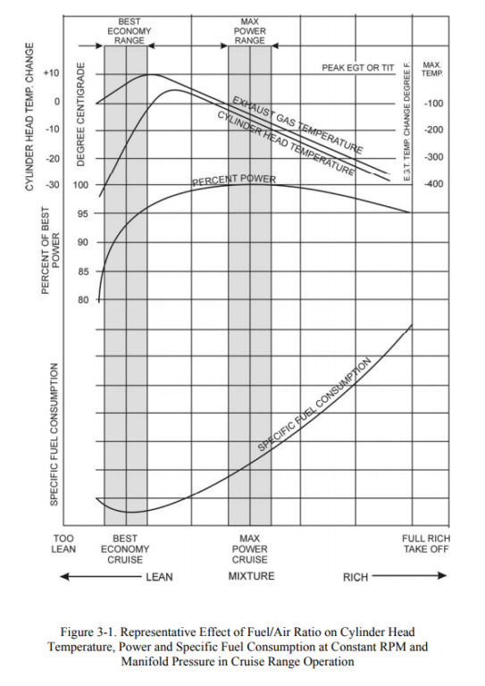
With all the engines done, we still had to ask how that power made it to the props, and Brett Sumpter was there to find every last 1% of power that was not QUITE disposed of properly in the HELICOPTER TRANSMISSIONS! We quickly learned that transmission losses can be associated with torque AND with RPM, AND with load on the rotor AND with output from the engine… but how much of each? Are transmission losses a constant POWER, or a constant TORQUE? Or not constant at all? I had just the person to ask about that: Lina Vera, at Beta, who designed the gearboxes for Ava, our electric eVTOL. Here’s what he taught to me, and I coded for you: Transmissions have two kinds of losses: The first is the BEARING LOSS. This is a friction that simply opposes rotation. The RPM does not matter. The torque from the engine does not matter. None of that matters. The bearing loss is simply a torque that opposes rotation, period. It’s from the friction in the bearings. But here’s the interesting thing: These losses are small! Our bearings are so good these days that the losses from this friction are basically negligible!
But here is what is NOT negligible: The SECOND loss: The loss from GEAR MESH. As the gears mesh in the transmission, they are RUBBING AGAINST EACH OTHER, the GREATER THE TORQUE, the GREATER THE LOSS! This is from the gear teeth sliding against each other as the gears turn, a torque loss that clearly increase as the engine torque increases. NOW we are seeing some real loss. And this loss goes linear with torque: The greater the torque, the more the friction losses between the meshing gears, and the greater the torque loss across the transmission system. So there are now TWO torque losses in the X-Plane transmission: The small, constant-torque bearing losses, and the much larger, torque-relative gear-mesh losses. Interestingly, for the helicopters, this gear-mesh loss applies only when the engine is actually driving the system: When the gears are carrying torque! In auto-rotation, this is not the case, so the gear mesh losses simply don’t happen in autorotation… but the bearing losses still do! Whew! OK, as you can see, for engines, this was not just me! Unlike most the rest of the flight model, this one was a group effort! Brett gave me heads-up on the need for transmission losses, Lino hit me up with the math.
Weight and Balance

All right, no matter the forces on the airplane, we must know the airplanes’ MASS and MOMENTS OF INERTIA to change those FORCES into ACCELERATIONS.
Forces are of no use in the sim at all if we can’t divide them by the aircraft mass to get acceleration!
Forces at locations are of no use in the sim at all if we can’t divide them by the aircraft moments of inertia to get angular accelerations!
So, just as important as all the forces we build up above: The mass and moments of inertia to turn those forces into accelerations!
So for X-Plane 12, X-Plane does a better job of estimating the moment of inertia of the airplane! It does this by looking at wings, wing thickness, engines, props, EMPTY fuel tank structures… the works! This is the secret to making the airplane really feel right in response to control inputs: That rotational inertia really matters!
And that is for the EMPTY airplane: But what about the payload that you ADD? Back in version 11, if you wanted to scoot the CG around, I just virtually offset the CG by applying a moment with G-load that simulated the entire aircraft CG being at the requested location. No change in moment of inertia, no distribution of mass: The CG was just sort of offset, as if by magic.
Same with weight: If you asked for more weight in the weight and balance screen, the weight was just sort of magically distributed across the entire aircraft, like a thin coat of lead applied across the entire aircraft skin.
Both of these things WORKED according to the THEORY of having the commanded weight and the commanded center of gravity, but neither of them really understood that the DISTRIBUTION of the weight on the airplane was subject to the loading stations that were available in the airplane… and that the moment of inertia of the airplane would be determined by the loading stations available on that airplane!
Like everything in version 12, “good enough”, isn’t good enough, so we had to take this to first-principles.
So here’s how it works: Now, all masses that go on the airplane are added at a LOCATION, and for version-12 aircraft, all of the physical effects of having those point-masses are simulated, including weight, balance, and moment of inertia: We start with the empty airplane, and then add the masses at the loading stations, just like we do in the real airplane!
So let’s take a tour: First, fire up Plane Maker and open up your favorite plane. Go to the STANDARD menu, WEIGHT AND BALANCE SCREEN, and over the PAYLOADS tab.
Here, you see all the payload loading stations that your plane can have.
If NONE of these boxes is filled in, then X-Plane won’t let you add any payload! So NOW is your chance to add some loading stations to your favorite plane in Plane Maker! Simply enter the max allowable WEIGHT to go in each loading station. Then enter the LOCATION of each loading-station. Then enter the TYPE of load for each loading station: PAX for passengers, cargo is also available, and notice the type FIXED. FIXED payload are ALWAYS set to this EXACT load in X-Plane: You will never ADJUST them in the simulator! This is useful for things you would not adjust before each flight, like the BATTERIES in an eVTOL airplane, or the PILOT in a LONG-EZ airplane, which must ALWAYS have a pilot on board to extend the landing gear!
Once you’ve entered the payload loading station locations, maximum loadings, and loading types, you can save the airplane.
Now open up X-Plane and select that airplane. Go to the DATA OUTOUT selections in the settings and CLEAR ALL DATA SELECTIONS. Then select items 63 and 19: Weight and Balance and Payload Weights. Now you see what the weight and balance and payload weights are, let’s go CHANGE them. Go to the WEIGHT AND BALANCE screen in X-Plane and drag the weight and balance sliders around. IF you have payload stations entered in Plane Maker for this airplane, THEN you will see the loads on each of those stations change when you drag the target weight and balance around! A nice way to keep an eye on your loads at each station, and resulting weight and balance… and of course the inertia that results.
NOTE: We can’t beak the laws of physics here: If you have one 5 pounds of payload in a Boeing 777… then don’t expect to be able to scoot the CG around much, eh? And feel free to run the weight and balance calculations yourself and check my work!
So that’s how we distribute the mass, but same as always, going through the code for version 12, we went through.. ALL the code.
And, as always, found the NEXT thing we weren’t happy with.
And this time it’s (sigh) the way the wings droop when full of fuel.
Once we had this first-principles weight load-out, and art from the artists that is so incredible that you feel like you’re looking at a real airplane, it suddenly didn’t look right if the wings on the airliners didn’t droop down a bit.
X-Plane 11 has wing-flex, where you enter the the mass fraction of the airplane that is in the wings… but we never specified if that mass is with fuel in the wings or not!
X-Plane 11 has wing geometry of course… but we never specified if that geometry is with fuel in the wings or not!
So we never specified what we MEANT, and we never varies the wing flex or mass with fuel.
So now, here are the rules, and the math for aircraft-authors:
Whenever you enter the geometry of an airplane wing, set that shape up to be the case with NO fuel on board.
Whenever you enter the wing mass ratio for wing-flex, set that mass up to be the case with NO fuel on board.
Then, in flight, IF you have SAVED the airplane in Plane-Maker version 12.00-Beta-1 or later, then X-Plane will ADD the mass of the fuel in all non-centerline tanks to the wings, adjusting the wing-flex accordingly.
So you can get that airliner design correct, where a heavy fuel load droops the wings down, but they come up under load, as we clearly see in the real A380 and B787. And the aero forces all do react accordingly… command-m a number of times in an airliner that has wing-flex to see flight model forces, to see the aero effects for yourself!
Oh and speaking of carrying weight, the slung loads under helicopters are now treated as cubes that surround whatever OBJ you are carrying so they should be able to be set down OK, and also we have PIPES selectable in Plane Maker as a way of carrying payload. We did this for some guys that drag chainsaws around under their helicopters to trim trees near power lines, and want to be able to train new pilots in the sim. This is a pretty esoteric, edge of the envelope type of thing to do in a flight simulator, but we have it working, meeting even that customers’ unusual, helicopter-based, 3-D VR-rendered needs successfully! X-Plane is really getting used for a LOT of flight training.
Oh and if anyone wants to use plugins to control these slung loads, then it’s:
Over-ride slung load size to plugin control:
“sim/operation/override/override_slung_load_size”
And set size:
“sim/flightmodel/misc/slung_load_min_xyz”
“sim/flightmodel/misc/slung_load_max_xyz”
Airbus Flight Control Laws
We’ve improved the Airbus Flight Control Laws based on input from actual Airbus pilots, so all of the rules above still apply, because they are rules of PHYSICS… and now an improved Airbus flight control system grapples with those physics to attempt to deliver a steady result, as the real airplane does. (But how much weather, how much weight, how far aft a CG, and how many failures, can it handle, before it can no longer give controlled flight? Only one way to find out…)
As well the yaw damper (sigh) which is used on the Airbus and other planes, is now as smart as it always SHOULD have been, by NOT trying to zero out the yaw rate, but instead zeroing out the yaw rate COMPARED TO THE IDEAL YAW RATE FOR THE TUN YOU ARE IN. In a turn, you WANT a little bit of yaw rate… it’s how you turn!
Conclusion
So as you can see, I could use a bunch of silly marketing adjectives here, but that wouldn’t do service to the actual work.
Now, in X-Plane 12, the model is either physically, logically, correct, or it isn’t.
And if it isn’t, then we don’t ship.
That’s why this release took forever, but I think we got it right. For an ultimate demo of how far the model can be pushed, get in the Cessna 172, load up the bag compartment to get that center of gravity aft, go up high, and try spinning it. Stick full aft, and held, perhaps with full rudder in a direction. This is no add-on effect: This is pure first principles. Hit command-M to see flight model forces to see what I mean, and see how they impact the airplane in flight.
Also remember to go to the DATA OUTPUT tab in the sim settings and scroll through and look at all the new data output options:
Battery states of charge, takeoff and landing distances (you have to FLY them to get the recording, though!) lift over drag and propulsive efficiencies and flight ranges in nautical miles, disc coefficients of drag and propwashes… the list just goes on and on and on, with dozens of new data outputs. You really need to fly with data output tuned on, and various flight-visualizations accessed with command-m, especially in a propeller-driven airplane, to see what X-Plane can really do!
Also remember to hit shift-M to have X-Plane dump a flight-model cycle to the disk so you can check my work if desired… that file output is hugely improved for readability.
OK, so we have the new flight model for the airplanes… and the air they move through.
Now what about some airplanes to experience all this awesome stuff?
For new planes we have:
A little Piper Cub to get really really low and slow..
Ditto that for a little Aerolite 103… gotta have an ultralight in there.
An RV-10 for some mid-size home-built flying: Low and slow enough to go anywhere, but fast enough to cover some ground…
An R-22 helicopter to REALLY feel rotor-dynamics with NO annoying computers in the way to hide the laws of physics from you…
An R-22 SEAPLANE variant to check out the new 3-D water, just for fun…
My Lancair Evolution, N844X, perfected down to the logos on pens I stole from the FBO in Burlington and velcroed to my dash!
F-14 Tomcat. The detail is… astounding. And the dynamics are… dynamic. Excellent demo of wing sweep… fly fast and slow with visible forces!
Cirrus SR-22 cause of course! It’s the first airplane I ever owned. It’s perfect.
Cessna Citation-X for the absolute highest civilian Mach number you will see… and a jet small enough to let you change your mind quickly.
And the grand-daddy of them all: The mighty Airbus A330. Fly this airplane. You will start to understand its’ size.
And an interesting note about the future: All of these improvements are making it to the MOBILE version as well!
X-Plane desktop and mobile are continuing to converge, as the mobile devices rapidly catch up to the desktop computers.
A convergence of these platforms is inevitable, where the computing PLATFORM is IRRELEVANT: All that matters is the input to the sim (anything from a full physical cockpit to nothing but a tilted phone) and output to the display (anything from a phone screen or monitor, to a set of VR goggles, to a level-D approved full visual system). The input and output are what matter… not whether the computing platform sits in your pocket or on your desk! And we are designing our code-bases accordingly for the future: X-Plane MOBILE is built from the same source code as the desktop version, simply with a different UI and suite of art resources… and these differences will surely evaporate over time.
And now, finally, as a little bonus, here’s a little write-up (un-edited) that I did as I was wrapping up the F-4 Phantom performance with the actual F-4 flight instructor! This is an internal company email to my internal alpha testers that I’m publishing here because it’s fun:
X-Plane 12 Flight Model Update – Supersonic Transition, Delta Wings and Mass Properties
Great to read about all the new changes coming. It really makes one more excited about the new product while reading about the massive slew of changes that have been made. One question that has stuck to me is how will snowfall accumulation be treated in the sim. Will snow accumulate or will it just be drawn as the packed snow “post plow” as described? If it will accumulate, as part of the new ground services will plows be included that operate on their own world to pack the snow? If not then this would be a neat addition post release
I didn’t code that part but when I set snow and then set it to warm temperatures I see the snow seem to deteriorate over time… I think we have that working OK… but maybe not perfect yet… hang on imma make a time-lapse and then maybe come back here and post what I find gimme some time….
OK I just checked it out: Right now, if you SET precip and freezing temps, then the whole works is SNOWED-IN as soon as you exit the set-weather window… but then if you go back in and set it to a higher temperature, the snow melts smoothly over time.. hmmm… 😐
That is not tots consistent… we are getting into things now where it is like “well what did you MEAN when you set snow? did you mean it JUST started snowing or HAS BEEN snowing?”
OK, I just tweaked the code. It was easy: Now when you se tRUNWAY CONDITIONS, then sure it sets the RUNWAY CONDITIONS… but the SNOW can ONLY build up melt down slowly… no instant-reset!
Sooooo…. switch form imagining winter in Boston to Summer in Nevada and…. the snow will melt in Nevada… over just a few minutes at 110 degrees!
This is my wildest expectations exceeded … can’t believe Flight Simming is as popular as it is X-Plane 12 looks set to be the benchmark for years to come
Austin, as I have told you before, you need to calculate the fetch of the wind on the water for seaplanes. It is not realistic that there are big waves in a strong wind … over a river! Seaplane pilots sometimes take off in a crosswind to avoid the waves if it is an offshore wind. Last time, you answered that it would require too much computer time to calculate it. But you could, from a certain height, in the direction of the wind, measure the distance to the shore.
Cheers, Michel Verheughe
Hi Michel! Yah I know.. the problem is, if the use SETS a wave height, we want to give it to him!!! We can’t figure out how to make the waves vary all over the place.. and still be exactly what the user entered in the weather set-up!!! Hmm……
On a similar note, one way to estimate wind on an open lake with no flags or chimneys around is too look at the wave patterns. You can see the wind shadow cast by trees on the lake shore.
So you look for the flat spot along the shoreline, and that will be the direction the wind is from, thus the direction you want to land towards.
Would be great if that element of seaplane flying would be simulated in XP!
Will the volumetric clouds cast shadows on lower cloud layers and the ground?
Yah! I remember coding simple cloud shadows 20 years ago… just a re-render of the flat, 2-D clouds above, but in half-solid black. Now… way more complicated. Ben did that part.
Lots of discussion about the 2-spool jet model, but how will XP12 handle 3-spool jets? How does it currently work in the A330?
Sorry… a slightly weak point… we only do 1-spool and 2-spool… so the N2 is just using a slow fuel-pump time or high-inertia to simulate the drive from N3. maybe we add that third spool to low-level physics at some point in time…
Austin,
Thanks for this great write up. $otherSim would never go into such detail about the process of making the sausage, and I really appreciate it.
I’m waiting it with impatience, as a real Private Pilot Licence I always wanted to have the best aircraft model as possible.
I hope that my own developed plugins to work with my own hardware cockpit would be compatible, if not I will redesign them of course 🙂
So how are the people who said this is just a reskin of X-Plane 11 doing? =P Interesting read and I can’t wait to buy X-Plane 12! Hell, I might go ahead and do the early access too!
Question RE: Helicopter Flight Dynamics…
In VRS (Vortex Ring State aka Settling with Power) there is a new-ish recovery technique that will reduce the altitude loss from on-set to recovery. It’s called the Vuichard Maneuver or Vuichard Recovery Technique. To perform this maneuver, instead of pushing the nose down to induce forward movement (which takes a bit of time relatively speaking), one adds collective (yes this increases lift and induces a further onset of VRS) but also adds sidestick movement and opposing pedal input. This would be right stick and left pedal, together increasing the response to provide lateral movement out of the VRS and decreasing the recovery time… and altitude lost.
The question is, would this be correctly modeled in XP12 flight physics? I’m assuming that since all flight surfaces are correctly implemented it should but I’d love to hear about actual tests of this maneuver and how much difference it makes in the the altitude lost during recovery… both in sim and in R/W helicopters.
All this is correct in the sim win v12.
All you need to do is get some lateral speed to get out of the wash.
I don’t care how you get it.
“Set the throttle open JUUUUST a hair to hold about 70% N1, 33% N1.” I guess Austin wanted to say 33% N2?
No. Jets idle at around 55% N2. A teeny bit of throttle will get you to 70% N2.
Impressive amount of detail has gone into the new simulation engine and overall product. I hope the implementation is multithreaded and allows for a minimum of 60fps on desktop and 90fps in VR, to make the experience also enjoyable, not only educational.
Good report, But..
Going forward XP dev works needs to reprioritize:
Cloud types, cloud rendering, rain and weather atmosphere effects: 20%
Wind currents and effects on flight model: 5%
New world rendering and scenery designer: 45%
ATC, AI, map and integration: 5%
Graphics, proper HDR, AA, DLSS etc: 15%
Graphics / multi core optimization: 10%
Statics, new aircraft, GUI, fmod, voices, multiplayer, training, flight planning, everything else: ZERO.
More than I needed but you will not get this kind of info (knowledge) from MSFS2020 never. Just can’t wait until the demo………..
The xplane team is once class act
Thanks,
Wow!!! And my first “simulator” was a Link trainer. (A black box with a stick, rudder, and six pack inside with a guy on the outside twirling it around and up and down.) How far we’ve come!
You got me at “GET AWAY, WILL SMITH! YOU’RE NOT WELCOME HERE! THIS IS ABOUT ROTORS, NOT THE SLAPPING YOU’RE THINKING OF!”
Can you recreate the volleyball and grid iron scenes from top gun yet, or will that be in a separate add on/Easter egg?
I think Austin will need to do some napkin math on volleyball lift and drag coefficients in a 1-G environment….
This is freaking amazing! Will you support electric powerplants, including battery, fuel cell and various hybrid configs at some point?
We have electric in v12.. batteries, motors, etc.
Great articlt, but: Too much use of uppercase words. With that use the effect targeted – to give more weight to something – gets loss. Anyway I enjoyed reading it. Thanks!
It would be interesting to see how all this comes together and how close can it get to the real world.
Get realistic terrain like from Google Maps or continue loosing 90% of the flightsim market to MSFS.
Ehhh…mmmm .. noup !. X-Planners are sticked to X-Plane because of what it offers in other more delicate areas of the flight simulation. There seams to be a huge improvement on the graphical part, though.
Two questions:
Won’t all these fabulous new features overwhelm my (not so new) computer?
What will overall night lighting look like in VR from a few thousand feet up?
Hi Austin, I haven’t read the whole lot yet, so I’m sorry if You actually have answered it already….
But I have read about the delta-wing vortex lift, and it is really great to have thát coming into X-plane, I really look forward to try out the effect….
– What I wonder is whether You also count in the drag that comes with vortex lift, as they do increase the drag drastically….???
Looking forward to the release, a lot….!!!
YES!!! Drag, and lift, and pitch MOMENT… from WHERE on the wing the lift is centered!
Yes lift and drag are basic starting points for sure!
Austin:
Is the delta wing pitching moment in ground effect modeled? For example, during the Concorde’s landing, the rear portion of the delta wing is quite close to the ground, and as a result, there is a relatively more lift produced on the aft part of the wing, resulting in a nose down pitching moment that the Pilot must compensate for with aft stick. The Colimata Concorde model pitches down in ground effect, which is not realistic. Also, is spin behavior modeled? The Extra 330SC model doesn’t recover like the real aircraft. Thanks!
I meant to say the the Colimata Concorde in X-Plane 11 pitches *** UP*** in ground effect, which requires an unnatural forward pitch input in the flare and doesn’t match the descriptions given by Concorde pilots.
Hate to say it, but its Vortex Ring State and not Settling with power you are describing in the Helicopter section… one is aerodynamic and the other is performance issue. But then again, it gets so mixed up by everyone incl FAA and EASA..
It is with the greatest expectation that I’m awaiting for X-Plane 12.
I believe in the continuation of the evolution of this magnificent SIMULATOR, always looking for the greatest reality in the world of aviation!
Good job guys!
X-plane? More like real life simulator, lol. The amount of physics in this is absolutely incredible. Great job.
Will you have the Boeing workhorse B737-800 ? If so, will the Zibo B737-800 be functionable in X-Plane 12 ??
Regards,
Jack
yah we include a 737… version 11 planes should work.. no expectation of major problems with zibo but ALL third parties should tune their craft to be BETTER with v12… with flight model changes, they should expect to tune their planes.
Will there be accommodations for flight training in X Plane 12? When/where can the early edition be purchased?
whow. I’m looking forward soooo much, it hurts 🙂
Great Austin, but PLEASE LISTEN to the sim community. MSFS set and raised the bar permanently. Very few people will care about leaf colours and other minor details. Its about satellite accuracy now where you can fly over “your house” and other landmarks. MSFS got the clouds you need to catch up or loose market territory. Dont be so stubborn, talk to Alphabet and get Google Maps on-board. Good luck!!
Nah. My experience, in 2500 flight hours or so:
Hours spent watching airplane, weather, flight dynamics, systems, planning, ATC, air traffic system, general terrain for avoidance: 2500.
Hours spent “looking for my house”: 0
Of course we’ll keep improving the scenery, but the stuff I mention above is higher prio.
I totally agree with this reply, it’s a flight simulator, a building 3500 ft away from a plane doesn’t affect how a plane fly, but the weather does….true to life scenery yeah looking forward to seeing that in the sim…in the mid-term….but, I’m excited to see the whole new transformation, clouds, sky, lighting….just hyped for the release! Great work thus far
That’s unfortunate. I’m thrilled you’re as excited by the physics as you are, and I’m grateful that you’re channeling that into making X-Plane better. But you need to understand that there is at least a segment of your market that:
1) will never fly an aircraft for real, and therefore won’t know (or care) how accurate the physics are;
2) fell in love with flight simming _because_ of what we could see out the window.
This is wish fulfillment for me. I use X-Plane because I _can’t_ fly in real life. So scenery matters to me. A lot. And getting it to look good in X-Plane is hard.
I understand that you sell professional versions of this software for real-world training purposes, and I understand that to you personally, technical accuracy trumps all. But by hand-waving requests for better scenery as lower priority, the message that I’m getting is that I am not your intended customer.
Of course, you do you. Like I said, I love your passion and enthusiasm, just wanted to share my thoughts.
I care about leaf colours and other minor details like an amazing weather system, wet/icy runway conditions, 3d-water with correct sea-plane physics and an atc for vfr.
I have also looked for my house in XP a couple of times, I have to admit, but with simheaven X-Europe I can see it clearly. Doesn’t have the right colour, but _that_ is a minor detail to _me_. And most of the time, I fly at places I don’t live at, so I don’t care if every single house is correct.
Still good to hear scenery and autogen is going to be improved, better is always better.
Everybody is different, there will be enough users for both sims. : )
Mmm.. noup .. I don’t think the strongest market for X-Plane is that. X-Plane has a different market and focuses more on delicate aspects like those mentioned above.
You are explaining Vortex Ring State and not Settle with Power in the Heli section… one is aerodynamic and the other Performance related
Ciao Austin,
Ringrazio il tuo team e te per il grande lavoro svolto e dopo per “aspera ad astra”, onore e gloria a X Plane 12.
Austin,
very interesting read, tremendous work!
However I was looking for an update on IFR flying. Like many others I am using X-Plane not for armchair flying but to practice approaches, go-arounds, holds etc. to keep currect for IFR.
I fly a DA42NG in Germany, bought XP-11 last summer, a capable PC plus the Realsim Gear G1000 suite with a trustmaster stick and a switch panel and rudders, but the GA button does not really do everything it is supposed to do for a G1000 airplane. Ok there is no DA42 in XP-11 so I used the vision jet, but the GA button there only does part of what it is supposed to do, at least not at EDMA.
So I was hoping the IFR functionality would be improved in XP-12 for the G1000 with a GFC-700 autopilot. Plus there are various releases of the G1000 software, on the (old) G1000 the highest release with WAAS is SW-version 15, but then there is of course the newer G1000NXi. So I am (still) hoping there is a way to set the G1000 SW version in XP-12 and that XP-12 then mimics the functiuonality of the G1000, so that XP-12 can really be used for IFR training. If you have to use workarounds in XP-12 to mimic the real functionality, or the workarounds one has to do on the real airplane are not mirrored in XP-12, than the benefit of using XP-12 for IFR training is limited.
All the rest of all the tremendous work you have put in is great but not really required in this level of detail if one just wants to shoot approaches and practice go-arounds and holding patterns.
Thanks and keep it up!
Joe
Hi, have you tried Aerobask DA62?
What are you doing about frame rates and multi core? With all these changes what will happen to frame rate? I imagine it will get worse which is not good for those trying to build computers to run this program
Nah… The flight model still runs just 5% to 10% of the total load! It’s 90% to 95% scenery load!
Just curious, with all these fantastic Changes and planes will we need a Main frame computer just to run the New Xplane 12? What are the minimums that still let us render it with some quality?
Couldn’t read it all but really enjoyed that which I did. The go-around video was outstanding. Thank you for taking the time for this update. Looking forward to X-12.
Austin, thank you for taking the time to really lay out the background and changes coming in X-Plane 12!.. and to the entire team for all their hard work and creativity that is certain to set a new standard!!! Hearing and seeing all these capabilities come alive is truly awesome!!! I can’t imagine how much time it took you to put together such a thorough document, greatly appreciated!!! For sure will need to read this several times to comprehend everything you’ve stated! Great news re-confirming about X-Plane 11 aircraft and scenery, there are some really sweet 3rd party developments that I want to use with X-Plane 12. Very impressed with your Development Team and extremely excited for Early Access!!!
This is incredible work on the physics side of things, looking forward to test run.
I did not hear anything regarding CPU & GPU loading, this I’m curious about.
We use WAAAAAAAAAAY more GPU now… and yes there is more threading.
Austin’s article, when he gets into the technical weeds, was a bit over my head, but I did get the gist of the changes. As with any of the major upgrades, I get concerned about the increased computing power vis a vis the improvements. Also, I’d love to see a lost of the 3rd party and freeware developers who have written upgrade patches for 12. Of course, I could alway stay with using both 11 and 12 at my option. I’d certainly compare FPSs.
Austin, you are a true artisan and I know that you design to the very high bar that you set for yourself. You always have. I will get 12 if only for the tricked out seaplane performance/realisim. it’s nice to enjoy the work of a team where “good enough” is never good enough. Thanks I’m advance for 12. Take your time and satisfy yourself.
As a glider pilot I am really looking forward to the new thermal model- overall this sounds like an amazing upgrade, and will set a new standard for sure! And bonus for a Piper with Tundra tires!!!
Wow, this post itself represents a ton of work–on top of all the work that is described herein! Thank you for all of this detailed info. I appreciate the time it took to do the actual work and the time it took to write this up for us.
Cheers!
does this mean the tires will deform or will the model just sink in the ground? if you say make REALLY big low pressure tundra tire?
we need some soft body animation support
@Austin, your explanation on the prop wash got me thinking. So the wash speeds up behind the prop according to an S-curve you propose. I am not sure whether you have looked into this more deeply. I reckon the phenomenon is a venturi effect.
Energy is added at the prop, and from there energy will only decrease over time due to friction within the air body, and eventually the air will calm down. Assuming conservation of energy, this means that the body of air behind the prop can only speed up because its volume is being reduced at that point. An obvious cause for that might be the widening fuselage which will more and more squeeze into that propwash. So it’s a venturi effect.
Assuming I am on the right path, this would mean there is not some static S-curve that describes the phenomenon, but it is more likely the ratio of the prop disc to the part of that prop disc that is blocked by aircraft structure that accelerates the prop wash speed. So as a consequence, it will be different depending on how large the prop is in comparison to the shape of the fuselage. The effect will be more pronounced on a C150 than on N844X.
So if you are modeling a static gradient now, it might be more exact to relate it to prop disc and fuselage volume within that disc.
And a request: can you also make “sim/flightmodel2/engines/rotor_blade_slap_rat” available via UDP, so motion platform and transducer software have easy access to this metric?
Very much looking forward to the seaplane dynamics, as I have some experience, but it isn’t really viable to keep currency living in europe.
So, recovering from a stall in ICE will entail flying at less than half of stall critical AOA and lower than speed?
You need to recover with way LESS AOA, and MORE SPEED, than you might think.
This is incredible!
All that “new math” is making my head spin. I just hope it doesn’t kill my current 22 FPS on a 2018 MacMini with eGPU Radeon 580.
The jump to Metal caused me to break out the champagne. Hopefully the jump to v12 won’t put me over the porcelain throne.
Nah.. the speed is almost all limited by scenery… the FM is not really that big in frame rate cause computers keep getting faster. I see 120 FPS on my mac studio with minimum rendering options.
Thank you Austin for the outstanding overview of the upcoming capabilities to be integrated into the new X-Plane flight simulator. The time-space dependent real weather effects, enhance aerodynamic flight effects, as well as landing gear-tire interaction with the ground (i.e., rain, ice, snow)….make this flight simulation a true game changer!
I’m not sure every simmer is an aerodynamics engineer, but I do know every simmer familiar with X-Plane wants XP-12 to become available ASAP. I doubt anyone really takes time to read long explanations about how things work, they just want to work them. I appreciate all the time it took to author such an article as this, but most simmers would rather see you get this version out to all of us without spending hours away from the project typing, spell-checking, typing, spell-checking, and on and on just so we can see you know your stuff. All we want is a launch date, a working product, and if we want to learn more about your process we could read it within the new sim (stashed away within the docs). Knowing something great is about to happen, and how it is happening, is a great thing for simmers who like to sit around and read for hours … I really don’t think simmers do that much. Aerodynamics Engineers, especially those still in school, would love this article. Otherwise, we just want out XP-12.
The FM is now done… we’re just waiting on scenery now. So I’m doing my release-notes (above) while ben finishes rendering and scenery, and artists tune the airplane art.
Just three questions:
1. When are we likely to see XP12 released – 2022 or 2023 ?
2. How much for owners of XP11 to upgrade ?
3. Will it be “better” than MSFS and if so, how ?
Thanks
Reg
1: This year.
2: Same price for everyone: $59.99.
3: Depends what you mean by “better”. For me… no possible hope of a contest between the two.. they are not even in the same universe. For those that only want to “fly over their house” get MS… though it seems anyone would get tired of that after 20 minutes… but I guess that’s just me…..
And me… and thousands more believe me!
Thanks Austin for clear and direct answers. I realised “better” was a stupid ask but I had already posted and couldn’t edit.
Very good overview, and I look forward to use XPlane 12 :)! Im building a new PC and will defintely would like to spend time keeping my knowledge active and also prepare for a possible Airline Interview.
Happy to see x -Plane maturing
Austin, tank you very much for your enthusiastic post and reports.
X-Plane was already awesome in terms of what we could simulate (We used V9 to test-flight our SAE AeroDesign RC airplane back in my university days).
Seeing the improvements you got into the Physics is just amazing and very welcome. The mass distribution and the Jet Engine performance inputs is something that affects me directly, and I am very thankful for the improvements you mentioned. I can’t wait to dial in the numbers and check the results.
Keep up the good work.
Wishing you and the X-Plane team, all the bast and looking forward to meeting you guys at one of the next conventions.
Cheers,
Athos
I’m excited!
To the X-Plane12 developing team.
It is amazing what you doing for XP 12.
Please enhanced or fix the city lights at night which are switched on in the distance when you fly closer to them.
It’s always an immersion killer for me.
And multicolour city lights please.
Agreed… I want this as well… I want better city lights in the distance: No hard-cut point.
Ben wrote that code, and he agrees as well… A thing we will do at some point, but maybe not 12.00.
Hello
First, thank you for all the work you are doing.
I would like my Seaplane to be able to be attached to the dock, so that it would be attached while I prepare for the flight or finish it. Thanks for taking my suggestion.
Well I dont think this is a cult … Austin needs sleep – but at least there is humor in this (sorta Tristrium Shandy novella). We even got variable names – oh boy.
I am very encouraged by the comments about the details of the look of everything especially the Aircraft and pavement comments ! Brown is not a primary color.
Yay ! I got distracted several times, and did not search for “weather” is that gonna be a focus ? will they include a PLUGIN for weather in XP 12 that we all have used and paid for (Ultra Weather – never worked for me).
Regards for all the hard work. MSFS doesnt mean what you think it means.
Absolutely incredible!
With this incredible number of “simultaneous” background calculations it begs to be asked:
How parallel will the new XP12 be? Is it designed to make the most of 32+ cores? Will there be an upper hardware limit or will it just use cores as available and adjust the code execution frequency automagically to accommodate the actual hardware it is running on?
This is all very exciting. Is there a change to leeward-side down-draft along ridgelines at low altitude? In 11 it appeared as though a pure laminar model was being used based on airmass movement and terrain slope. This created a seemingly unrealistic vertical velocity near cliffs below 200 feet AGL.
” Is there a change to leeward-side down-draft along ridgelines at low altitude?”
yes… the wind follows the terrain at low altitude, yes.
Excellent work. Thank you for your constant effort to improve: that is Art. O:)
What an amazing post Austin. You have an incredible energy and enthusiasm for your product and I love it. I am so excited to read all this, maybe XP12 will be the first sim to accurately model flight, how incredibly exciting! I can’t wait to see what you are doing with ground textures and autogen and airports. It needs to be real, so I hope that you done a deal with Google images. The best of luck to you always, X-Plane is a classy product that I have always enjoyed flying in.
All that realism sounds just amazing!
I wonder though – now with the new tire model, could that be “implemented” for building´s surfaces (hard,soft)?
I think helicopters landing and stackering objects on top of each other.
This is what I really miss in X-plane <3
Not to mention the description of the aerodynamics of an autorotation are not quite correct. It’s a common misconception that when you bottom the collective you are going into negative pitch and that’s how the auto works (the pinwheel description). But it’s nothing to do with negative pitch of the blades which most helicopters do not do to begin with. And everything to do with managing the aerodynamic forces along the three regions of the blade while in an autorotation. The upward airflow and the forward (rotational) movement of the rotor blades is just enough to keep the total aerodynamic force vector tilted forward of the axis of rotation. I might be misremembering but it seems like the R22 blade at its flattest point was still at 2 degrees. And while not recommended, an R22 can initiate a zero speed auto at 200ft AGL. Without negative pitch.
It was interested to see so many concepts that I developed for the RW designs Twin Otter being mentioned here.
I worked on things such as:
Cabin Temperature
Engine Oil Temperatures / pressures
Brake Temperatures
Electrical Current, and effects on generator / battery temperatures.
In all of those concepts, I tried to go back to first principles.
Taking brakes as an example
Heat (Friction) Energy delivered to brake discs = Force x Distance = Aircraft Mass x Acceleration x Distance / number of disc brakes used
Then Disc Brake Temperature = [Heat Input (Friction) – Heat Output (Convective Heat Transfer with Air + Stefan Boltzman Radiation + Latent Heat of vaporisation of water in rainy days) ] / Heat Capacity of brake disc
So then I could relate braking effectiveness with brake temperature.
Speaking of brakes, hydraulics were also a consideration. The electric hydraulic pump fed an accumulator, which took time to build pressure. Once the accumulator was at required pressure, pump turned off. Then the accumulator would deplete with brake displacement or flap operation. At a low pressure setpoint, the pump would kick in again. If the pump failed, or there was no power then you still had hydraulic pressure. In that instance you could pump the brakes and watch the pressure gauges drop down with each brake pedal displacement. That in turn affected braking performance.
Cabin Temperature has a similar treatment, but I also considered passengers as a heat source, as well as a source of moisture.
Basically, if you close the doors on the ground, then humidity builds up and causes internal condensation on the windows. So those ventilation settings become important!
If it’s 20 degrees C outside and cloudy, then those passengers will warm up the cabin.
If it’s sunny outside, then those passengers complain as the temperature rises even further without any ventilation to compensate. The higher the temperature, the more irate they become! That’s the Stefan Boltzmann law in full effect.
I also considered the engine oil temperature and considered how it would warm up and cool down. So I took the engine mass, worked out the heat capacity, assumed how much heat from combustion was lost to warming up the engine. Then I also made assumptions about how effective the oil coolers were. That depended on ambient air temperature, velocity, and density, and other factors such as oil filter clogging.
Then I could dial in considerations such as engine wear that depended on engine power x time, oil temperature, and oil quantity (especially when oil was low / empty).
Before I knew it I had engine maintenance that the pilot had to consider. Failures were no longer random, but related to how you treated the aircraft. You couldn’t just “fix all systems” in flight. That was interlocked. You had to be on the ground, engines off to fix your faults. In “expert mode”, it also cost you time. An engine replacement cost you 24 hours of “service mode”.
As for the electrics:
– I2R losses were considered, especially during engine starts. You could watch your incandescent lights dim during such sequences.
– If you forget to turn off the electrics when you quit X-Plane, current and timestamp are stored and compared when you next start X-Plane. You might get a flat battery if you leave it overnight.
– Battery health depletes with charge/discharge cycles, so that’s an additional maintenance item.
– Transient Voltage damage to avionics caused by sudden changes of current were also considered.
All told, I took an aircraft with relatively simple systems, and made all those systems interact with each other. The result is that when you fly a simulator aircraft, there consequences for abusing your aircraft, and you can’t just simply “fix all systems” to get out of trouble.
So to see some of these concepts make their way from custom Lua code and into the core x-plane model is encouraging.
Hi Anthony, would you be able to contact me?
Thank you,
Greg
Hello,
The landscape = the landform + the vegetation (and the houses 😉 )
You don’t talk of the landform but it’s important for the gliders and the mountain airfields.
Do you updated the landform?
Thanks
Great work Austin. My simple questions are will my current fleet of X-Plane 11 aircraft be compatible with X-Plane 12? Will I need to purchase a new set of disks? How much disk space will I need?
Great work Austin. My simple questions are will my current fleet of X-Plane 11 aircraft be compatible with X-Plane 12? Will I need to purchase a new set of disk? And how much disk space will I need?
Can we expect to see a “new” plane maker, or at least with a different color pallete as shown in the snipets here?
It is really a long flight, took me hours to finish it. Cannot wait to see the new X-Plane 12 flight model
If you do what I say, you will really cope with mfs 2020.
1- If you can, make the orthophoto system easy for anyone to do and integrate it into the xplane system. If possible try to integrate the ortho system with a cloud base xplane.
2- improve night lighting, make it as close to reality as possible. MFS 2020 still looks better than xplane in this regard.
3- Make the default Airport environment closest to reality.
4-make clouds visually most realistic.
5- Make the default landscape autogens closest to real world data.
6- Roads-cars-boats-trains-bridges-make them as close to reality.
7- Increase texture quality. if possible integrate directx 12 or dlls technology into x plane. Improve shading quality.
Thank you Austin for the update. Looking forward to having a release date.
Question: Will there be an enhancement on the runway conditions? Sometimes during a regular snowy day (X-Plane 11 after the precipitation begins), braking actions falls down close to NIL veeeery quickly =D. Any chance that the RWY condition is reported on the ATIS as per New GRF concept (or at least in a simplified way).
Thanks !
This sounds really good , looking forward to it so much ,I have question we have new water physics and 3D wave , is the wave height being increased as 20ft seems too shallow for stormy or extremely windy conditions
I am wondering, with it being probably the most popular large jet, why the Boeing 777 is not featured in X-Plane 12, or even 11?
Hi Mr Austin,
Any chance we get support for more complex FLCS systems options in Plane Maker, in order to properly simulate a F16 Viper?
For example options I would like to see available :
– a negative G- limiter option
-a AOA limiter option which can be altered for different loads and dependand on defined mach speeds or generally a more configurable AOA dependant control deflection limiter
– a roll rate limiter
-possibly some kind of a role departure prevention system
Basically anything that would be required to setup a Viper FM in regards to indepth FLCS complexity.
I know thats a lot… but Thanks.
Hello Everyone,
please let me put the focus on this key word: Ground Fog.
Looking from above like scattered/overcast slightly puffy Stratocumulus with a cloud base mathematically below ground.
Diving into it on approach is an invaluable experience.
Will X-Plane 12 be able to simulate it?
Woah! Simply amazing work going on here! I watched all the Dev interviews on YouTube. The level of enthusiasm, energy, and sheer amount of awesomeness has got me riled up with excitement!!! I recently returned to flight simming from my days of Falcon 3.0, 4.0 on my 486 PC! My simming came to an abrupt halt after my PC became obsolete. Anyway, I cannot wait until X-Plane 12 comes out. As a 3D designer, when I heard that Photometric lighting was going to be implemented, I immediately smiled and grinned from ear to ear! Ohhhh man, I’m so stoked! Everyday, I’m hunting for news about the upcoming release of X-Plane 12. So count me in! I’ll be purchasing my copy the moment it goes live for the public! Wooohooo!~ 🙂
Hi,
thanks Austin for this encouraging and exausting post!
Two Questions regarding the weather system:
– Does XP12‘s new atmospheric model take also AIR DENSITY and AIR PRESSURE for all the atmospheric levels straight out the GRIB-files OR will they be somehow approximated by simply using the standard atmosphere PLUS the ISA temperature deviation PLUS the QNH offset?
– If they are approximated like so, will the air humidity (dewpoint) at least have an effect on the air density in XP‘s atmosphere?
All that matters pretty much regarding DENSITY ALTITUDE and how high you are REALLY flying above the earth while crusing along on FL320. For example, if you have a high QNH on ground but a low pressure area in the upper troposphere, you would be flying significant lower on the same (pressure) flight level. You couldn‘t simulate that just by using a simple temperature offse fron the standard atmosphere and the QNH.
It was already wrong in XP11 and just because of that, the dev from the Hot Start Challenger 650 has been adressing this by implementing an own atmospheric model in order to get his simulation as real as possible.
The biggest problem I still see with X-Plane is the colours – the general look of the world. You can show virtually any image from ANY version – including clips from 12 and instantly it is absolutely, 100% X-Plane. And I don’t mean that in a totally positive way. It used to be bland and dismal, lacking contrast and almost post apocalyptic in some areas. Now it appears to be be moving into the area of being seemingly WAY overdone with ‘cinematic’ effects with FAR too much saturation. The world doesn’t look like that. 12 reminds me of ‘FLY’ (the sim) and FLY 2 where it was so overdone it simply did not look real at all. I really hope this changes and it is ‘wound back’ from level 99 to about level 6 or 7. The ‘shadows’ in 11 are so bad that they need an OFF button. Luckily there are scripts that can do most of it. I really hope 12 does not suffer the same in the release. What we are seeing at the moment is, I hope, simply ‘overdone’ for some dramatic effect. Fingers crossed. I am really hoping for something exceptional. I am also really hoping for proper multicore CPU usage as well……… That seems to have dropped off the radar ?. – We can hope. Keep up the development.
Yay, I’ve been wanting more than 8 engines for a while, now we’ll be able to build things like the B-36, DO-X, and Helios solar plane.
Dear Austin!
Just Awsome Nerdulation. Reality Bites!
Can I plead with you to repeat your F-4 pilot experience with a real Concorde Pilot before they become extinct, like moon-landing astronauts? And SR-71 pilots?
Maybe you could make it a three-some with Florian of Colimata?
Just imagine the Best Airliner Ever Built with spot on physics from 0 to Mach 2.2 …
ogival delta wings, 13 dynamic fuel tanks, dynamic CP, dynamic CG & MI, dynamic trans-sonic engine airflow intake management, re-heat (we’re British please, none of your crass American “afterburner” stuff) …. just said that ‘coz I know you have a sense of humour …
Swoon ….
Will there be any new aircraft added? – I would love to see the AN-225 brought back to life.
I remember long, long ago 🙂 when the aircraft didn’t even had visible undercarriage in XP, but, wow, did my computer deliver good frame rates! The answer was: “Do you want to stare at the wheels, or do you want to fly the plane?”. I wish to have the option(s) to turn down scenery intensity to really ‘nothing’ (in 10, 11, 12…) (btw with 10 my current favourite as I can push the unneeded visuals down for fast simulation of aircraft) thus to rather have high frame rates and smoothly handle a plane for a perfect landing than look at puddles on the taxiways. It is like buying a hairdryer for my bald head, just to find that the power supply of my green solar panels die when I turn it on due to the wiring… now I have to buy a new house with more outlets just to allow for consumption of something I rarely use.
when is the columbia 400 going to be available for x plane 12, have it in 11 and love it.