X-Plane offers several instrument types that display moving maps, the most popular one being map_s_HM.png which emulates an instrument found in airliners and allows for several display modes, like an HSI view, a NAVMAP view and a PLAN view.
Customization – graphics
Customization of the map display is possible by editing the map_s_HM-1.png, map_s_HM-2.png, map_s_HM-2.png and map_s_HM-4.png graphics and supplying the graphics specific for your aircraft through the library system (the path is cockpit/EFIS/EFIS_maps). These png files can supply alternate symbols, colors or fonts to generate the style of the navdisplay.
Up until X-Plane 11, it was not possible to change the overall scale of the map, so supplying a texture with bigger dimensions did not lead to bigger symbols or bigger text. Therefore, a very big map instrument would render very small and thus difficult to read symbols and text, even if the customized graphics were provided in a very high resolution.
Customization – parameters
Starting with X-Plane 12 it is possible to independently scale symbols and text of the navdisplay, and also change the relative locations of symbols and labels. The scale chosen is independent of the resolution of the supplied graphic files. Supplying a graphic with double the resolution will not increase the size of the symbols. Configuring the scale parameter to double the size will not increase the resolution of the texture, so the result will look blurry. To achieve a crisp and legible bigger navdisplay you will thus need to supply both a higher resolution texture and also configure a bigger scaling factor.
The customization parameters are supplied through a text file specific to the instrument that you supply for your aircraft in the path cockpit/EFIS/EFIS_maps. The name of the text file corresponds to the instrument, so if you are customizing the map_s_HM-3.png with new symbols, the text file to edit is the cockpit/EFIS/EFIS_maps/map_s_HM.txt.
The syntax of the file is as follows:
A
750 version
x   y
0 -143	// comment: rose offsets in expanded mode
0 -5	// comment: rose offsets in centered mode
2.5 2.5	// scale factor for symbol and text size
32 -15	// text label offset x and y in pixels at the provided scale
65280 -1 // 24bit color for the "magenta" line and absolute size of the compass rose
The first five lines are unchanged from previous versions of X-Plane and allow the lateral and vertical offset for the center of the map display in arc mode and rose mode. These pixel values continue to be unaffected by symbol scaling.
The next three lines are only read by X-Plane 12 and allow you to utilize higher resolution textures and further customize symbology.
The first scaling factor is applied to symbols and the second scaling factor is applied to text. They can be specified in single floating point precision. This way it is possible to scale text up more than symbols if needed for readability.
The last line provides the absolute offset from the center of the symbol to the bottom left of the text label attached to that symbol. In this example, the text label starts 32 pixel to the right of the center of a symbol and the bottom of the text label is 15 pixels below the center of a symbol.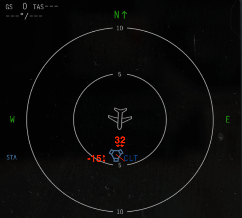
The last line allows customization of the ND MAP and plan mode where the FMS flightplan is displayed. By default, the active FMS route is a magenta line, but a 24bit value can be used to override the RGB value. In this example, 65280 is an RGB value of R=0, G=255 and B=0, thus a solid green line. The map scale is determined by the map range values of the array dataref sim/cockpit2/EFIS/map_range_steps in nautical miles, and the height of the compass rose texture (map_s_XX-3.png). If this is undesired, the array of available map ranges can be changed by plugin, and the size of “rose” can be altered independently from the texture by a non-negative value of the second parameter on the last line.