X-Plane 11.35’s bleed air system is an extension of the earlier X-Plane bleed air system, designed both for versatility and compatibility.
At the center of the new bleed air system is the center manifold which serves as the backward-compatible portion that is used by all airplanes, designed to provide basic bleed air and pressurization capabilities for existing aircraft.
Aircraft modernized for X-Plane 11.35 and later can make use of the left and right extensions of the bleed air system, and opt to use 1, 2 or 3 air conditioning and pressurization packs.
The system design is best understood with this diagram: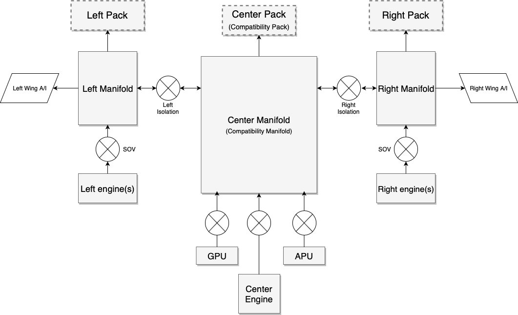
The center components provided for compatibility are clearly marked.
X-Plane legacy aircraft know only one pressurization pack, and one selector that selects the sources for this pack: left hand side of the aircraft, right hand side of the aircraft, and APU. Both APU and the center engine in a one- or three-engined plane are considered to be providing air from the center of the aircraft.
New to X-Plane 11.35 are: GPU bleed, left pack, right pack, wing-anti ice supply, and per-engine shut-off valves.
Another way to understand the system is as a Lancair (legacy X-Plane) overlaid with a King Air overlaid with a 747 – you will then understand how to design many more aircraft types with it:
1. Single-engine plane (Lancair Evolution or similar)
The center pack is the single source of cabin pressure. Packs L and R are always off because they don’t exist.
The bleed selector doesn’t care for left or right or both, the isolation valves have no function, the only available settings are: Bleed “off” meaning engine shut-off valve off and Bleed “on” (any of L, R or BOTH) meaning engine shut-off valve on. Bleed “auto” adds APU valve on (the single engine plane most likely doesn’t have an APU, but if it has, it would work), GPU adds GPU off or on. There’s only one duct, and only one available pressurization pack, center.
2. Two-engine plane with single pressurization (old King Air or similar)
The center duct supplies the one center pack that provides air to the cabin. The pack can be fed from the left engine, the right engine, or both. The bleed air mode thus maps to the isolation valves: left bleed air means left isol valve open, right bleed means right isol valve open, bleed both or auto mean both isolation valves open. If an APU was installed, it would feed into the center duct regardless of the isolation valve settings, controlled by the APU valve, just like the GPU.
3. Four-engine plane (resembling 747)
The system operates exactly like a 747 would: Three packs are available, per-engine SOVs, APU SOV and GPU SOV and two isolation valves work exactly like you’d expect when comparing the above graphic to the schematic of a 747.
4. Twin engine plane (737, A320, CRJ, ERJ, etc.):
Here’s where it gets interesting. For correct operation, one must turn off the legacy center pack and never turn it on again. That must be done actively by script or plugin, since X-Plane will never turn off the center pack – that would break existing aircraft!
The plugin can turn pack C off and pretend it doesn’t exist.
One can then turn on pack L and pack R as per the pack switches.
One can turn off or on the per-engine SOVs as per the engine switches.
Now the only remaining switch is the (single) isolation valve found in such aircraft.
This is where it gets airplane specific and one needs to look at a diagram for the specific airplane: Look up whether the APU and GPU feed into the left or the right from the single isolation valve. For the sake of explanation, let’s assume we are looking at the 737, where the APU feeds into the left duct and GPU feeds into the right duct.
For operation with the APU, the isolation happens to the right of the APU. That is, the isolation valve of the 737 with APU feed is the ISOL R valve in the X-Plane system (and ISOL L is always open). This way, center and left duct belong together, and are fed by left engine and APU. To the right of the isolation valve is the right engine.
For operation on GPU, the isolation happens to the left of the GPU! That is, the isolation valve of the 737 in GPU feed is now the ISOL L valve in the X-Plane system (and ISOL R is always open). This way, the left engine is to the left of the isolation, and GPU and right engine are to the right of the isolation.
Note that GPU and APU can never feed together – in real planes, the APU load control valve is also a one-way check valve. If theAPU valve was commanded to open while the system is pressurized from the GPU, it simply wouldn’t open. In that case, the system operates as GPU-fed until the GPU is off.
5. Twin engine plane (McDonnell-Douglas)
For a plane like the MD-80, which has two isolation valves, operation becomes very simple:
The center pack is turned off (by script or plugin) and never turned on again.
Pack L and pack R are turned on as per the Air Cond Cockpit and Air Cond Shutoff switches.
One can then turn off or on the per-engine SOVs as per the supply switches and fire handles. Both pulling a fire handle or turning off a supply switch should close the engine valve.
The left and right isolation valves separate the side systems with their respective packs from the center duct, into which the APU and GPU feed. These valves are thus direct mappings between X-Plane and and the MD-8x cockpit.
6. Three engined-planes
Because three-engined planes are very dissimilar in design between a 727, DC-10 or Tu-154, X-Plane makes no effort to resemble either – it is expected that custom plugin code will be needed to accurately simulate a three-engine plane.
Electrical power consumption
Having covered the pneumatic side of the system, let’s look at the electric side.
X-Plane has one electrical consumer for “HVAC” that until X-Plane 11.34 could not be controlled via datarefs or commands. From X-Plane 11.35 onwards, the following electrical loads are simulated with the various components of the system:
- AC compressor and fan take 100% of the amp load that is specified
- Fan only takes 10% of the amp load that is specified
- Fan and heater in flight mode take 100% of the amp load that is specified
- Fan and heater in ground mode take 200% of the amp load that is specified
Note that most of this is only relevant to GA planes, not airliners. Airliners do neither have electrical AC compressors nor electric heaters. Heat is supplied by the bleed air alone, it comes out of the engines so hot that it does not need to be heated. The cooling is provided by an air cycle machine driven by bleed air pressure itself, so it does not need lots of electrical power to run the air conditioning to cool it down.
So in an airliner, one would only ever use the fan function, so in Plane Maker, the amp load of the fan times 10 needs to be specified for the whole system, since we are never going to use the remaining 90%.
In a GA plane, the AC compressor is driven by electrical power, so using it will put you in the situation where X-Plane will use 100% of the specified amps.
Some turboprop planes, notably the King Airs and Cheyennes, have not enough heat from the engines to sustain cabin heating alone, so they use an electric heater grid consisting of 8 grids at 36amps each (that is the value for a King Air 90), four of them operate in flight, and an additional four can be activated on the ground when enough power is supplied either by both generators running, or by a GPU. That “ground max” heat setting will double the power consumption, as explained.
Datarefs
sim/cockpit2/pressurization/actuators/air_cond_on int y boolean Electrical air conditioning compressor on, consuming all the amps of rel_HVAC - not needed on airplanes with air cycle machines that drive the air conditioner off the bleed air power itself.
sim/cockpit2/pressurization/actuators/heater_on int y boolean Electrical heater grid on, 0 = off, 1 = flight max (consumes rel_HVAC amps), 2 = ground max (consumes 2x rel_HVAC amps, turned off by weight-off-wheels) - not needed on airplanes that are using hot bleed air and have no heaters
sim/cockpit2/pressurization/actuators/fan_setting int y enum Electric fan (vent blower) setting, consuming 0.1 of rel_HVAVC amps when running. 0 = Auto (Runs whenever air_cond_on or heater_on is on), 1 = Low, 2 = High
sim/cockpit2/bleedair/actuators/engine_bleed_sov int[8] y boolean Engine bleed air shut off valve, close or open
sim/cockpit2/bleedair/actuators/apu_bleed int y boolean APU bleed air valve, close or open. APU must be running at 100%N1 to provide bleed air
sim/cockpit2/bleedair/actuators/gpu_bleed int y boolean GPU bleed air valve, close or open. A GPU is supposed to be always available.
sim/cockpit2/bleedair/actuators/isol_valve_left int y boolean Isolation Valve for left duct, close or open. This separates all engines on the left side of the plane, the left wing, and the left pack from the rest of the system
sim/cockpit2/bleedair/actuators/isol_valve_right int y boolean Isolation Valve for right duct, close or open. This separates all engines on the right side of the plane, the right wing, and the right pack from the rest of the system
sim/cockpit2/bleedair/actuators/pack_left int y boolean Left pressurization pack, off or on. The left pack is supplied from the left side of the plane or through the left isolation valve and only available for airplanes made for 11.35 or newer
sim/cockpit2/bleedair/actuators/pack_center int y boolean Center pressurization pack, off or on. The center pack is supplied from center duct, which can be supplied from a center engine, APU, GPU, or, via the isolation valves, the left and/or right ducts. This pack is the only pack available for airplanes made for X-Plane 11.33 or older
sim/cockpit2/bleedair/actuators/pack_right int y boolean Right pressurization pack, off or on. The right pack is supplied from the right side of the plane or through the right isolation valve and only available for airplanes made for 11.35 or newer
sim/cockpit2/bleedair/indicators/bleed_available_left float n ratio Bleed air available in the left duct, which can come from left engines or through the left isolation valve.
sim/cockpit2/bleedair/indicators/bleed_available_center float n ratio Bleed air available in the center duct, which can come from a center engine, APU, GPU, or, via the isolation valves, the left and/or right ducts.
sim/cockpit2/bleedair/indicators/bleed_available_right float n ratio Bleed air available in the right duct, which can come from right engines or through the right isolation valve.
sim/cockpit2/bleedair/indicators/engine_loss_from_bleed_air_ratio float[8] y ratio Bleed air being sapped from the engine, stealing efficiency from the compressor. Writeable only with override_pressurization set
Commands
sim/bleed_air/engine_1_off
sim/bleed_air/engine_2_off
sim/bleed_air/engine_3_off
sim/bleed_air/engine_4_off
sim/bleed_air/engine_5_off
sim/bleed_air/engine_6_off
sim/bleed_air/engine_7_off
sim/bleed_air/engine_8_off
sim/bleed_air/engine_1_on
sim/bleed_air/engine_2_on
sim/bleed_air/engine_3_on
sim/bleed_air/engine_4_on
sim/bleed_air/engine_5_on
sim/bleed_air/engine_6_on
sim/bleed_air/engine_7_on
sim/bleed_air/engine_8_on
sim/bleed_air/engine_1_toggle
sim/bleed_air/engine_2_toggle
sim/bleed_air/engine_3_toggle
sim/bleed_air/engine_4_toggle
sim/bleed_air/engine_5_toggle
sim/bleed_air/engine_6_toggle
sim/bleed_air/engine_7_toggle
sim/bleed_air/engine_8_toggle
sim/bleed_air/gpu_off
sim/bleed_air/gpu_on
sim/bleed_air/gpu_toggle
sim/bleed_air/apu_off
sim/bleed_air/apu_on
sim/bleed_air/apu_toggle
sim/bleed_air/isolation_left_shut
sim/bleed_air/isolation_left_open
sim/bleed_air/isolation_left_toggle
sim/bleed_air/isolation_right_shut
sim/bleed_air/isolation_right_open
sim/bleed_air/isolation_right_toggle
sim/bleed_air/pack_left_off
sim/bleed_air/pack_left_on
sim/bleed_air/pack_left_toggle
sim/bleed_air/pack_center_off
sim/bleed_air/pack_center_on
sim/bleed_air/pack_center_toggle
sim/bleed_air/pack_right_off
sim/bleed_air/pack_right_on
sim/bleed_air/pack_right_toggle

sim/pressurization/aircond_on
sim/pressurization/aircond_off
sim/pressurization/heater_on
sim/pressurization/heater_grd_max
sim/pressurization/heater_off
sim/pressurization/heater_up
sim/pressurization/heater_dn
sim/pressurization/fan_auto
sim/pressurization/fan_low
sim/pressurization/fan_high
sim/pressurization/fan_up
sim/pressurization/fan_down