X-Plane 12 can simulate both ice accumulation and window de-ice effects as well as rain drop/wiper visual effects on aircraft window surfaces. This article explains how to implement icing visual effects only. Rain effects are discussed in its own dedicated article, “Windshield Rain Effects”. This article assumes you are familiar with:
- X-Plane 3D objects (*.OBJ files )
- UV layouts
- RGBA image channels
- xplane2blender / UI locations
💡 NOTE: X-Plane 12.1+ introduces significant changes to the windshield ice and heat simulation from previous versions, which had many problems. Any RainGlass OBJs previously configured with THERMAL sources, and exporting from XP2B V4.3+ using an export target version prior to 12.1 will NOT have window heat functionality. The exporting of the legacy
THERMAL_sourcedirective have been removed for all XP version options prior to 12.1.If you have exported out RainGlass OBJs with XP2B 4.3+ to support XP targets < 12.1, yet still desire to use the legacy
THERMAL_sourcedirective, then you will need to manually edit the OBJ and enter the directive and its parameters by hand. This directive and parameters are described further below for reference.
Enabling Ice Effects
Ice effects are automatically included on any window OBJs configured for Rain Effects. See the Rain Effects document for more info if you haven’t set up your RainGlass OBJs yet. When the conditions warrant, and in the absence of any window heat, the window will begin icing over uniformly at a rate dependent upon the conditions. X-Plane’s icing algorithm considers temperature, moisture, airflow and heating when calculating ice accumulation on RainGlass OBJs.
Icing Inspector Tool
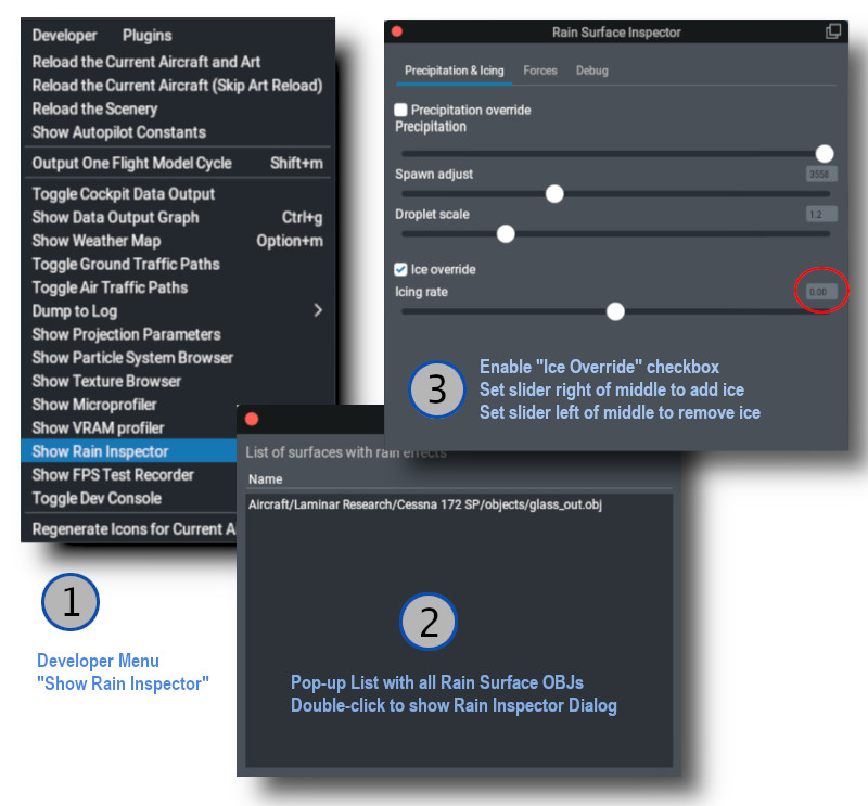
The same tool that is used to debug / inspect Rain Effects is also used to debug / inspect icing effects, so you don’t have to configure X-Plane’s weather to test your work. The image below shows the sequence for use.
💡 NOTE: For the “Icing Rate” slider. The middle position is 0 (red circle below). The right side of the slider adds ice and the left side of the slider will remove ice. If you are wanting to test your thermal texture deicing effects quickly, you will probably want to move the slider to the right to add ice, and then return it to the middle zero position and then activate the window de-ice system to observe the effects of your thermal gradient texture.
Thermal Sources Gradient Texture
In reality, windshields are typically deiced using either resistance (electrical) heating elements, or by using hot air blowers. Both of these are examples of thermal sources. Thermal sources typically apply heat to specific areas of the windshield glass and the heat radiates out from that area across the windshield. This causes the ice to melt in a progressive pattern, melting nearest the heat source first and progressing from there. X-Plane models the progression of this heat flow via a 8-bit RGBA “thermal texture”, UV mapped to your RainGlass OBJ and using color gradients across the UV islands of the windows to model the movement of the heat.
X-Plane uses the four channels of the thermal texture to simulate up to four independent thermal sources. Most aircraft typically have only one or two thermal sources.
The image below shows an example texture where a fully saturated color pixel, i.e. 100% Red, Geen, Blue or Alpha(white) represents maximum heat flux and a fully black pixel represents zero heat flux. Note in the example below that there are no fully black pixels on the window glass because if there were, the window heat would not melt ice in these locations.
The gradient texture is quite straightforward, typically painted by hand using gradient tools in graphic apps like Photoshop or GIMP. Remember that a fully black alpha channel (when thermal source [3] is not used), will make your image transparent.
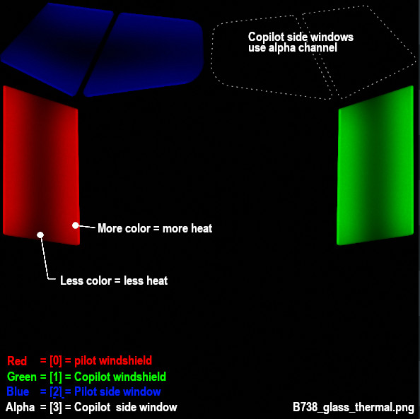
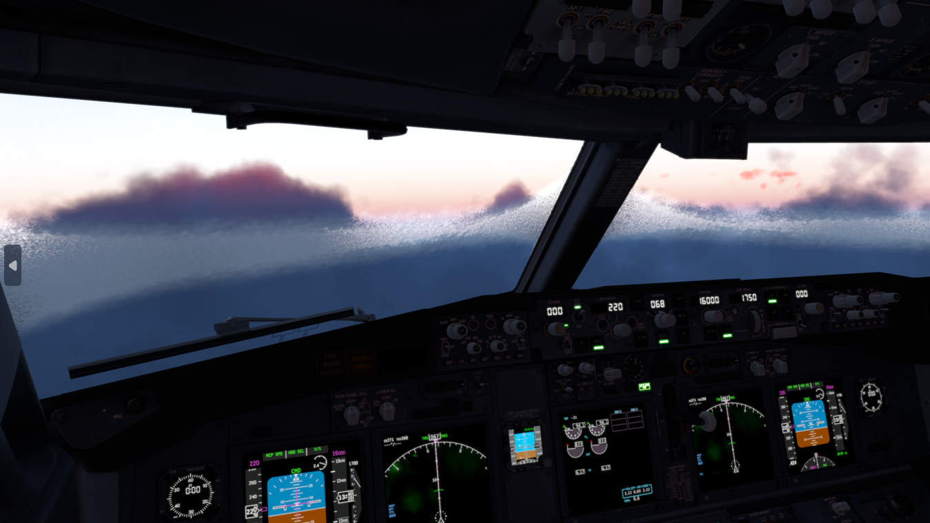
The image above illustrates how the thermal sources for the main windshields (Red and Green), are at the top and bottom of the windshields, and ice melts there first and then the heat moves towards the center of the window. In X-Plane the effect looks like so. For a hot-air blower fan configuration, you may have a radial type of gradient pattern, etc.
💡 TIP: Use a lower resolution THERMAL_texture to achieve better and more realistic looking heat propogation behaviours.
XPlane2Blender Settings
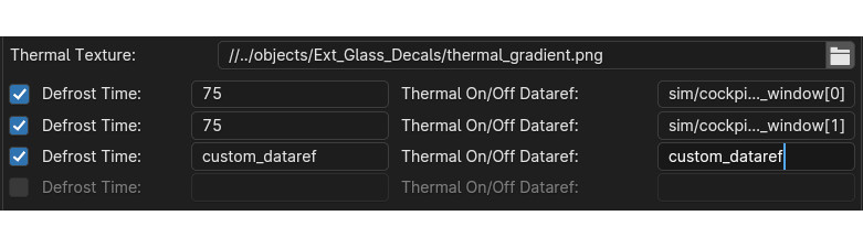
The XP2B settings for the thermal sources for window heat are found on Blender’s Scene tab in the collection settings (see image below). To configure your window heat, you enter the path to your thermal sources texture, presumably in the objects folder somewhere, and you enable however many thermal sources you need, up to 4 total.
For each thermal source you enable, you enter the Defrost time, in seconds. This field can be a fixed number or a dataref. This time represents how long, in seconds, a thermal source takes to fully deice a fully iced over window, assuming no ongoing ice accumulation. A shorter time represents more heating power. If you use a dataref, then you can alter this value at run time to simulate adjustable heating levels.
Next you enter the Thermal ON/OFF dataref. These datarefs, when 0, disable the window heat and when non-zero (usually 1), enable the window-heat. X-Plane have default datarefs for turning the window-heat ON/OFF for each source, which are listed further below.
The thermal settings in Blender will be exported to the OBJ GLOBAL settings in the form of two directives in the OBJ header section: one entry for the thermal texture file/path and one entry for each thermal source configured in Blender.
THERMAL_texture    path/to/texture/thermal_texture.pn;
THERMAL_source2   <index>    <rate_seconds or rate dataref>   <on/off dataref>
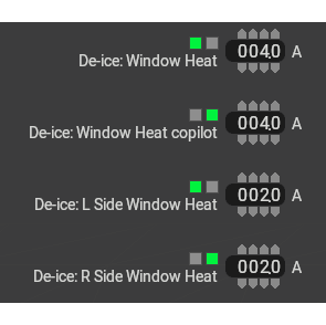
The exported windshield heat thermal parameters for the default B738, which uses four sources are shown below. Note that the ON/OFF datarefs are X-Plane’s status datarefs and not the window heat actuator/switch datarefs. The status datarefs take into account any system failures. You don’t want your window heat effects to be ON if the system is failed.

Power Consumption
You can configure the power consumption of each thermal source via PlaneMakers’s Standard Menu > Systems > Bus Loads Tab (the first one). When the status datarefs are 1, then X-Plane will add a current load to your electrical buses. These are fixed electrical loads only.
If you need to simulate a variable power window heat system and want to vary the power consumption of the thermal sources, then you will have to do so via plugin, adjusting your defrost time via dataref, calculating your power consumption and adding the load to a bus via sim/cockpit2/electrical/plugin_bus_load_amps[n]
Icing Commands and Datarefs
The following datarefs and commands are used with the Window heat / icing system.
        //  Actuator Datarefs (switch, button, whatever)
        sim/cockpit/switches/anti_ice_window_heat       // switch, 1st window
        sim/cockpit2/ice/ice_window_heat_on_window[N]   // switch, where N = 0-3

        // Actuator Commands
        sim/ice/window_heat_on                          // 1st window
        sim/ice/window_heat_off
        sim/ice/window_heat_toggle

        sim/ice/window2_heat_on                         // 2nd window
        sim/ice/window2_heat_off
        sim/ice/window2_heat_toggle

        sim/ice/window3_heat_on                         // 3rd window
        sim/ice/window3_heat_off
        sim/ice/window3_heat_toggle

        sim/ice/window4_heat_on                         // 4th window
        sim/ice/window4_heat_off
        sim/ice/window5_heat_toggle

        //  Status Datarefs.  Takes into account failures. e.g. can drive annuns
        sim/cockpit2/ice/ice_window_heat_on             // status, 1 window only
        sim/cockpit2/ice/ice_window_heat_running[N]     // status

        //  Failure State Datarefs
        sim/operation/failures/rel_ice_window_heat
        sim/operation/failures/rel_ice_window_heat_cop
        sim/operation/failures/rel_ice_window_heat_l_side
        sim/operation/failures/rel_ice_window_heat_r_side
Legacy Icing
It’s highly recommended to use the THERMAL_source2 directive with X-Plane 12.1.0 for any new aircraft development. The legacy THERMAL_source command still works in X-Plane 12.1.0, but the visual icing effects have inconsistencies with the X-Plane systems model with regards to how much ice X-Plane tracks on the windshield versus how much is visually rendered.
The syntax for the legacy THERMAL_source command is:
THERMAL_source <heat in ºC dataref> <on/off dataref>
…where the <heat in ºC dataref> is clamped between 5º and 20º C and then gets interpolated into a rate between 5 and 20 seconds.
Here is a short video tutorial on cockpit window de-Icing
No add’s. Hope it helps!
Rico
https://youtu.be/xsQnymL1PaE?si=FPIzkaBmYZ54crQd