Basics
New 3D trees in X-Plane consist of two main parts.
- The first part of a tree definition is a 2-d billboard side view of the tree. These operate almost identically to X-Plane 11 trees. In X-Plane 12, the side billboard always faces the camera and there is only one per tree.
- The second part is one or more 3-d models of the tree that are used for close up rendering. X-Plane dynamically animates the 3-d model based on wind parameters.
X-Plane automatically uses the 3-d model of the tree for close rendering and transitions to the 2-d billboard for far views for performance.
The two parts of the tree use separate texture and materials – the 2-d textures and material is shared by all 2-d billboards in the .for file; the 3-d textures and material is shared by all 3-d models in the .for file.
This guide requires some basic Blender knowledge like adding vertex groups and weight painting.
Textures
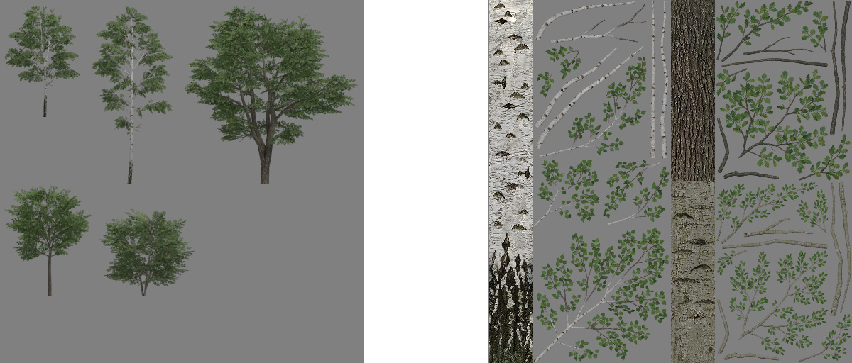
Both parts use separate textures – one for billboards and another for 3D parts. This is also the main prerequisite – all billboards and all 3D parts for all trees (all species) within a single *.for must be in a single texture sheet. A typical pair of textures may look like this:
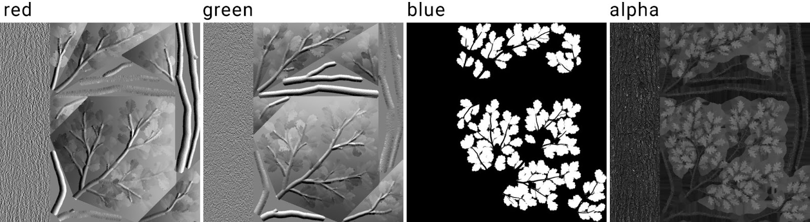
X-Plane 12 offers a new type of shader called translucent. It was designed specifically for 3D vegetation. Unlike a typical PBR shader, it has a different usage of the normal map blue channel. Instead of metallic property, it determines translucency. White color means fully translucent (leaves) and black means no translucent (solid parts – trunk). Here is what a typical normal map may look like:
Creating Trees in Blender
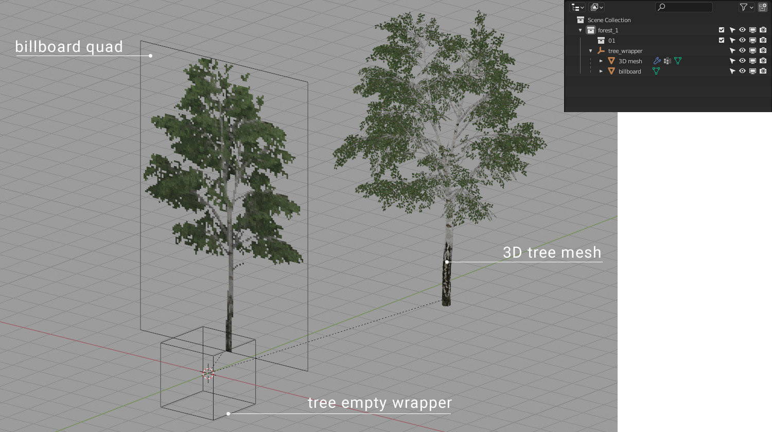
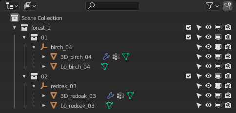
In Blender, all parts are organized in a hierarchy and in collections by strict rules. A single tree consists of three (or more) parts. The top-level object is an empty wrapper (Its name is used for the tree name on export). This parent wrapper must have two child objects – a billboard (single vertical quad) and a 3D tree (mesh object).
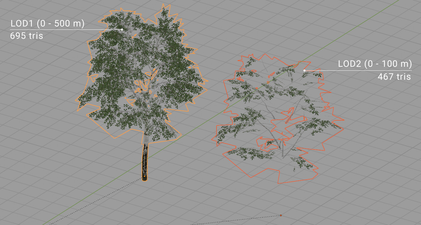
Each tree can have up to three 3D meshes. The reason is more per-tree LODs that can be additive. The typical use is: the first LOD mesh (0 to 500 m) has all triangles that are facing upward. The second LOD for a shorter distance (0 to 100 m) has all triangles that are facing towards the ground and thus don’t need to be visible for a bigger distance (bottom of branches). This is highly recommended for better performance, in particular when using high polycount on 3D meshes.
Trees are organized into forests using collections and each forest needs two levels. The top-level collection (right under the Scene root collection) is the forest itself. It consists of nothing but other collections. Those collections represent forest layers and all names must start with a numeric value (01, 02, 01-conifers, etc). This value is used as a tree layer index on the export. Obviously, all trees (with all their parts) must belong to some “layer” collection.
Parameters
All important parameters in Blender can be found in the properties editor but they’re spread across various tabs. All parts of a tree must be organized in the proper hierarchy and collection in order to get the options tab visible.
Global forest options can be found on the scene tab. Besides the main “Export” button the most important parameters here are the file name used on export, tree spacing, and global LOD distance. A separate tab for each existing root collection is shown. A collection is treated as a separate *.for on export once it has some filename entered.
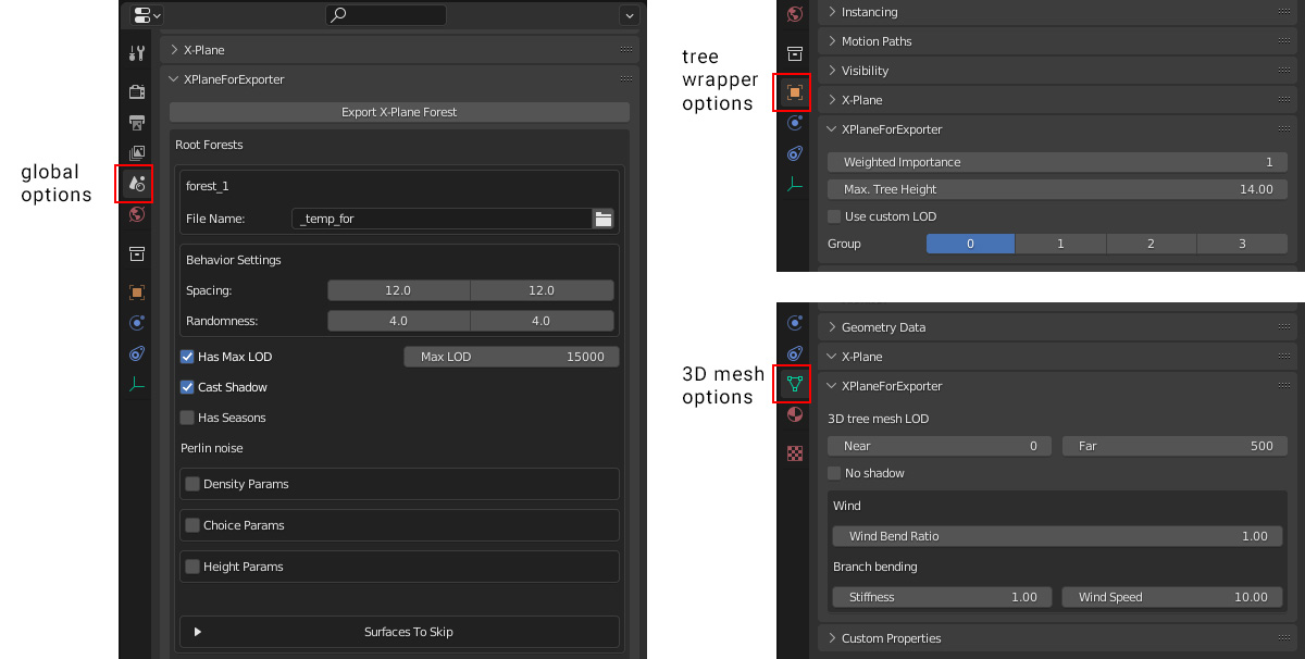
The tree root object (empty wrapper) has all options on the objects tab. The “Weighted Importance” value is a relative occurrence of the tree within a forest layer. “Max tree height” is the size limit of the tree. The minimum height is determined from the real size of the tree billboard (in other words, trees are prepared in Blender in their minimum size).
3D tree mesh-specific options are on the object data tab. 3D tree mesh LOD values are set to 0 and 500 by default. This is also the recommended value for all trees that are intended to cast shadows because 500 meters is currently the default max shadow distance in X-Plane. Shorter distances might cause popping shadow artifacts, but for some types of meshes it is not important, such as bottom facing geometry.
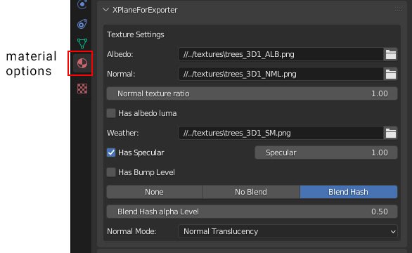
In addition, both billboards and 3D meshes have material options on the material tab. It is recommended to use blend hash and normal translucency mode for both materials.
Adding Wind Effects
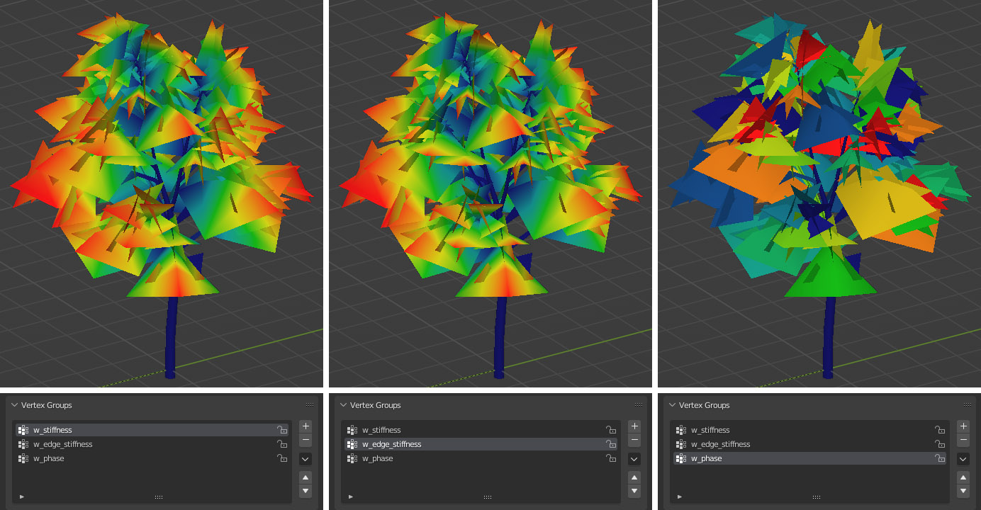
3D trees can sway in X-Plane’s dynamic wind. In order to do so the mesh needs additional vertex data. In Blender we have three vertex weight data channels: w_stiffness, w_edge_stiffness, and w_phase. These names are mandatory and case sensitive!
The stiffness channel (w_stiffness) is used to displace mesh vertices horizontally in the wind direction. The maximum distance of displacement (in meters) is defined by the stiffness parameter on the mesh data tab. It is a multiplier of the vertex data value.
Edge stiffness (w_edge_stiffness) is used to displace mesh vertices vertically (vertical oscillation or swaying).
Phase data (w_phase) is used to shift various branches’ movement in time. This can avoid uniformity in the look of the whole tree’s movement.
Stiffness and edge stiffness data might look very similar in most cases. Maximum weight value is on the tip of the branch and zero near the trunk. Phase data is different however. The whole branch usually has the same weight (any value in range 0 – 1).
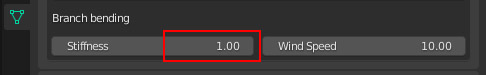
On top of that the whole tree is bent by wind. This bend is calculated automatically from the ground to the top of the tree. The stronger the wind, the greater the bend at the top of the tree. There is a calibration value on the mesh data tab that can tweak the total amount according to tree height.
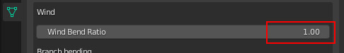
The default value of 1.0 is calibrated for a 10 meters tall tree. This value might change on the tree shape and the artist’s desires however. Here are a few examples:
10 m tree 1.0
20 m tree 0.5
30 m tree 0.3
5 m tree 1.6
Rock 0.0 (no bend)
Seasons
At this time the exporter has no automatic support for creation of seasons. It has to be done manually. To do so, make a copy of final *.for and change the texture to a different season variant. More info about seasons in different document (link?).
Tips & Tricks
- The exporter is still in a very raw stage. Code isn’t error proof so you have to follow strict rules to avoid errors on export.
- All parameters in the Blender UI have a tooltip with descriptions.
- It is recommended to use one forest per one Blender scene.
- Everything except proper forest collections must be turned off (excluded from View Layer) on export time.
- Try to avoid extremely high polycounts. A typical big tree mesh can have 1000 – 2000 triangles, or 3000 – 4000 for very big, old trees.
Can I get a sample Blender file for this?