For this tutorial, you will need a copy of the Beechcraft A36 Bonanza created in the tutorial “Creating a Basic Aircraft in Plane Maker” or you can download the files here.
Understanding the Panel Creation Workflow
To begin, get Plane Maker running (recall that the Plane Maker application is located in the X-Plane directory) and open the Bonanza. Open the Standard menu and click Panel: 2-D. You’ll be greeted by a very plain panel background with no objects on it.
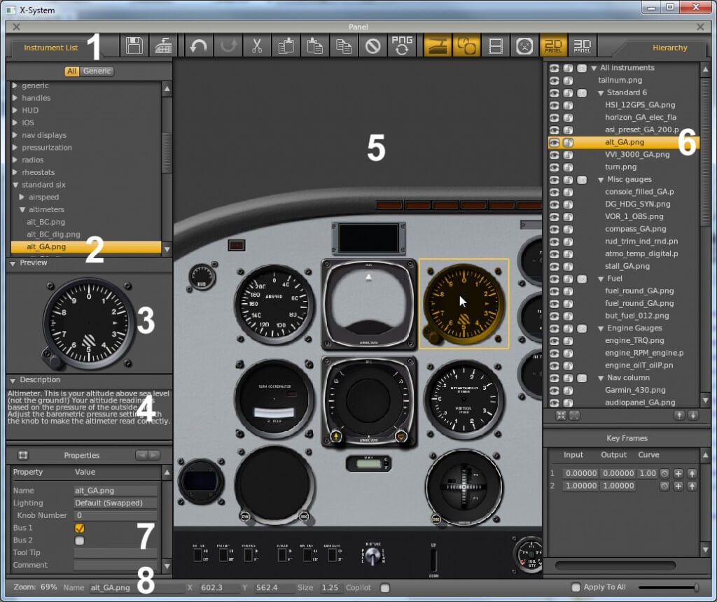
Creation of the panel is pretty straightforward. First, make sure the Instrument List is visible by clicking its tab if needed (labeled 1 in Figure 1 above). Find the instrument you’re looking for in the instrument list and click on it. For instance, in the image above, the general aviation altimeter (labeled 2) is selected. With an instrument selected, you can see what it will look like in the Preview tab (labeled 3 in Figure 1 above). Beneath this is the Description tab (labeled 4 in Figure 1), which details what the instrument does.
Taking up the center of the screen is the layout pane (labeled 5 in Figure 1 above). To add an instrument to the panel layout, drag it from the instrument list into this pane. Once there, click the instrument once to select it. With it selected, you can drag the instrument around to reposition it, or use the arrow keys to move it by very small amounts. If there is more than one instrument in the panel, guide lines will appear to which the instrument will “snap”, allowing you to align instruments perfectly.
When an instrument has been added to the panel layout, it will appear in the Hierarchy list (labeled 6 in Figure 1 above). You can select an instrument from the layout pane by clicking its name here. Additionally, you can set its status to visible or invisible by clicking the eye next to it, and to locked or unlocked by clicking the padlock.
To select multiple instruments, hold down either the Control or Shift keys and click as desired. To group instruments, select them and press the G key. Double-click an instrument to change its name.
When an instrument is selected in the layout and hierarchy panes, the Properties tab (labeled 7 in Figure 1) will display its settings. This includes which electrical bus the instrument is on, what Tool Tip (if any) will be displayed when it is moused over in X-Plane, and what lighting is used on the instrument.
Finally, in the very bottom of the window is the status bar (labeled 8 in Figure 1 above). Here, you can see the level of zoom for the panel layout pane, the position of the currently selected object, and its size (as a ratio compared to its original size).
Tips for the Panel Layout Pane
Use the = and – keys or your mouse wheel to zoom in and out in the panel layout pane. Right click (or hold the Control key and left click) on the panel and drag it to pan the view left and right. Hold the Alt key to view which electrical bus each instrument is on. Click and drag to form a box that selects multiple instruments. To delete an instrument, select it and hit the Backspace key.
Creating the 2-D Panel
To create our example panel, we found an image on the Web of a real A36 Bonanza’s panel and (loosely) based our instrument selection and layout on that. Creating custom instruments is beyond the scope of this tutorial, so we used the closest approximations to the real instruments that we could find in the Plane Maker instrument list. If you’re interested in creating custom instruments, see the Generic Instruments page of the Plane Maker manual.
Creating the Background
Before beginning the layout, you will want to create a basic version of the background panel image you will use. Plane Maker will supply a default panel image based on your cockpit setting in the Viewpoint window, but you may want a different image for a number of reasons.
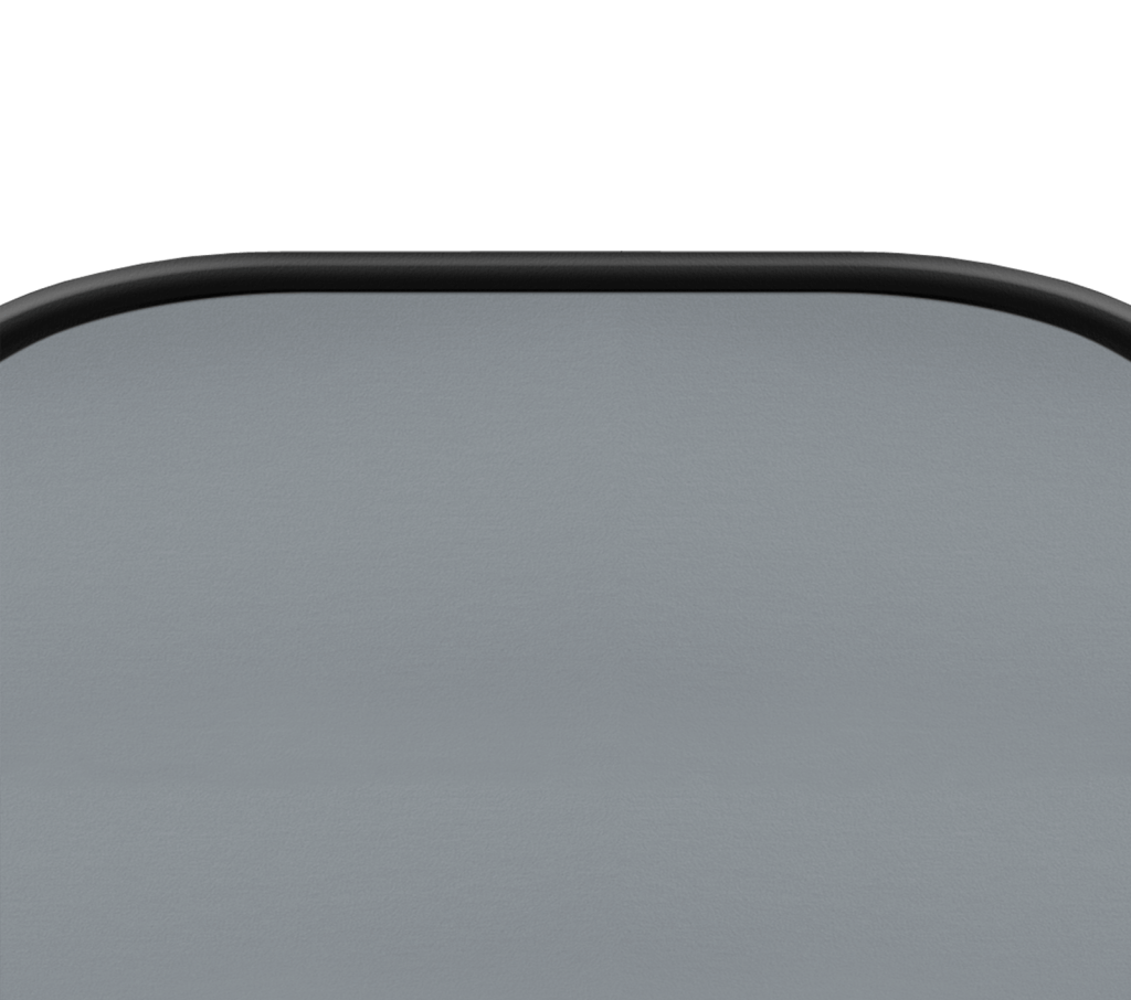
For our example aircraft, we modified the default general aviation panel to make it 1600 pixels wide, with both “ends” of the panel visible (instead of only having the left side in the image). A width of 1600 pixels was selected so that the panel will be usable, albeit a little shortened, in the smallest X-Plane window available (which is 1024 x 768 pixels), but it will also look great in a large, widescreen window of, say, 1920 x 1080 pixels.
If you want to customize the panel background, you’ll want to create at least a basic version of it before beginning the layout so that you don’t have to rearrange or resize your instruments later.
Our example cockpit image, before customizing it, is here:
Panels used in Plane Maker can follow one of two naming conventions. The old convention is simply to name the file “Panel.png” (without the quotes, of course). As of version 9, Plane Maker will still find a panel named this way. The new convention, and the one you should use when creating new aircraft, is to name the image to match the panel setting in Plane Maker’s Viewpoint window.
For instance, if the cockpit setting in the Viewpoint window is set to General Aviation (as in our example Bonanza), the cockpit image will be named Panel_General.png. If it were instead an airliner, the image would be named Panel_Airliner.png.
The official names for panels are the same as in Resources/bitmaps/cockpit/-PANELS-/ and are:
- Panel_General.png
- Panel_Airliner.png
- Panel_Fighter.png
- Panel_Glider.png
- Panel_Helo.png
- Panel_Autogyro.png
- Panel_General_IFR.png
- Panel_Autogyro_Twin.png
- Panel_Fighter_IFR.png
In order for Plane Maker to find your background, you must (re)name it using one of these conventions and save it in this folder:
- [Your aircraft folder here]\cockpit\-PANELS-\
Thus, our example aircraft’s panel image had a full path of:
- G:\X-Plane 10\Aircraft\Bonanza A36\cockpit\-PANELS-\Panel_General.png
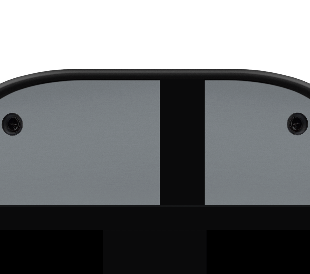
After you get your layout complete, you’ll probably want to come back to this image and customize it further–for instance, to add a column of a different color. You can find the finished version of our example Bonanza panel below.
Adding the Instruments
Once your Panel.jpg image has been placed in the correct folder, it should appear the next time you open the Panel window in Plane Maker. Once it’s loaded, you can begin dragging and dropping instruments from the list into your panel.
For our example panel, we chose to use the S-Tec System Fifty-Five X autopilot. This is a complete autopilot system modeled as a single instrument in X-Plane. You can find it in the “autopilot” folder in the instrument list.
You can download the .acf file of our example A36 Bonanza with the completed 2-D panel here: Bonanza_A36_with_Panel.zip
Creating a 3-D panel
Creation of a 3-D panel requires the use of a 3-D modeling program, which is beyond the scope of this tutorial. For more information, see the 3-D Panel section of the Plane Maker manual.