In X-Plane 11, we added two new features aimed at making joystick configuration easy for users:
- “image maps” that show you a picture of your joystick, with each of its buttons/axes labeled, and
- detailed default configurations for joysticks.
Both are described in the .joy file corresponding to your joystick. These files are located in Resources/joystick configs/.
Creating a default joystick configuration file
The easiest way to create the default joystick configuration: plug in your joystick, configure it as you’d like, then hit the “Save as Default for [device]” button there on the joystick configuration screen.
That will output a .joy file wherever you’d like (recommended that you stick it in Resources/joystick configs/). You can confirm it worked by hitting the “Reset to Defaults for [device]” button and confirming that none of your axis or button assignments changes.
At this point, if you were to delete your preferences, when you plug in your joystick, you would see that your previous configuration gets loaded—your joystick would be instantly ready to use!
Creating an image map
Our image maps consist of two things:
- a PNG image, which we’ve gotten clearance from a joystick manufacturer to distribute with the sim, and
- information in the .joy file noting the pixel coordinates of that PNG image where buttons, axes, & hat switches should be labeled.
So, suppose we have an image that is 1,000 px on each side. If the very center of that image corresponds to a particular button, we’d put a line in the .joy file to the effect of “Button x should be labeled at position (500, 500).” (We’ll get to the actual syntax below.)
Unlike the default joystick configuration, we can’t auto-generate the image map. So, you’ll need to use an image editor to figure out where in the image each label for your buttons, axes, and hat switches should go. So, you’ll specify the coordinates for these things in pixels, with (0, 0) in the upper left of the image.
The easiest way I’ve found for getting these coordinates (if you don’t want to spend a zillion years in Photoshop hovering over portions of the images and noting the pixel coordinates in the Info tool) is to use an online image map generator. Here’s how that works:
Upload the image you want to work with.
- Click the square or circle button.
- Click within the image wherever you want to add an annotation. A new line will appear in the source at the bottom of the window, giving you the coordinates of that shape. We need only the first two (x, y) coordinates.
- Continue clicking Add Area and noting the new coordinates until you’ve gotten everything you need.
See the “View” section of the following file format description for the syntax of the image map text.
Notes on the image files
X-Plane only supports .png images with an optional transparent background. While there are no official size limits, we recommend the image be no larger than 2000×2000 pixels to avoid impacting sim performance. X-Plane will also scale large images automatically while maintaining the image map coordinates you specify.
Nitty gritty: a sample .joy file, as of X-Plane 11.20
See examples of finished .joy files in X-Plane 11/Resources/joystick configs.
I
1100 version
JOY
# ^ The header; must be the first thing in the file, verbatim.

# Operating system(s) this file applies to.
# Windows, macOS, and Linux will index the axes differently, so a file
# that correctly configures your joystick on one platform is *not*
# guaranteed to work on the other.
OS: Windows
# Other valid options:
# OS: Mac
# OS: Linux
# Zero or more device names (provided by the operating system, as seen in the UI) that this .joy file describes.
# (Note that you need at least one name or one ID, described below.)
# If more than one device is named, we're saying that *any* of those devices should be configured
# using the *same* defaults and the same image maps.
Name: [device name]

# Zero or more USB identifiers (vendor ID + product ID) that this .joy file describes.
# (Note that you need at least one ID or Name, described above.)
# If more than USB identifier is given, we'll use this .joy file to configure *any* of those devices.
# You can specify the IDs in either hex or decimal form.
# For instance, the following are equivalent:
#    ID: VID:0x046DPID:0xC214
#    ID: VID:1133PID:49684
# ...since hex 046D == 1133, and hex c214 == 49684.
ID: VID:[vendor ID]PID:[product ID]

# Optional: Specify the name X-Plane should display for the device in the user interface
# (if this is different from the name the operating system provides)
Display: [device name override]

# Zero or more view sections
# These will be presented in the UI, and you can select different views for the same device
# (e.g., you might have one looking at the front of the device, one looking at the back,
# and a third looking at the throttle quadrant). Presumably you will annotate *different*
# controls for each view.
View: [view name]
-----------------------------------------------------------------------
Image: [image_name.png]

# Then, within the view section, you can zero or more of the following:
#   - buttons
#   - hat switches
#   - axes
#   - axis groups

# Buttons are easy; just specify which button you're talking about, and where in the image you
# want the "dot" for that button positioned.
# Note that these (x, y) pixel coordinates---like all the coordinates that follow---use the top left as (0, 0).
Button [button index]: [x coordinate in the image] [y coordinate in the image]

# Buttons can also take an optional *label* to display in the UI, like this:
Button [button index] ([label for UI]): [x coordinate in the image] [y coordinate in the image]

# Axes, like buttons and hat switches, can take an optional label.
Axis [axis index]: [x coordinate] [y coordinate]
Axis [axis index] ([axis label]): [x coordinate] [y coordinate]

# In addition, axes can take an optional *axis direction*. This must be one of x, y, or z (lowercase).
# If you provide a direction, we'll use that letter when labeling the axis in the UI.
# So, the following are also valid axis labels:
Axis [axis index] ([x/y/z]): [x coordinate] [y coordinate]
Axis [axis index] ([axis label]; [x/y/z]): [x coordinate] [y coordinate]

# Finally, you can optionally group axes together in the UI.
# For instance, you probably don't want to display the x and y axes on your joystick separately.
Axis Group ([label for this group, displayed in the UI]): [1st axis index in this group] [2nd axis index]
Axis [index] ([x/y/z]): [x coordinate in the image] [y coordinate in the image]
Axis [index] ([x/y/z]): [x coordinate in the image] [y coordinate in the image]

# Zero or one assignment section
# This describes the default configuration for the device.
################################################################
# NOTE:
# You almost certainly don't need to know the syntax for the
# assignments section, because you should be auto-generating
# it from an actual configuration (by hitting the
# "Save as Default for [Device]" button in Settings > Joystick).
################################################################
Assignments:
------------------------------------------------------------------------

# Any number of axes, buttons, and hat switches.

Axis [axis index]: hidden
Axis [axis index]: [joy use]
Axis [axis index]: [joy use] reverse
Axis [axis index] Type: linear or centerable
Axis [axis index] Calibration: auto
#	Valid joy uses are:
#	 joy_use_none	joy_use_ptch	joy_use_roll
#	 joy_use_hdng	joy_use_thro	joy_use_coll
#	 joy_use_lbrk	joy_use_rbrk	joy_use_prop
#	 joy_use_mixt	joy_use_heat	joy_use_flap
#	 joy_use_vect	joy_use_swee	joy_use_sbrk
#	 joy_use_disp	joy_use_reverse	joy_use_elev_tr
#	 joy_use_ailn_tr	joy_use_rudd_tr	joy_use_thro1
#	 joy_use_thro2	joy_use_thro3	joy_use_thro4
#	 joy_use_prop1	joy_use_prop2	joy_use_prop3
#	 joy_use_prop4	joy_use_mixt1	joy_use_mixt2
#	 joy_use_mixt3	joy_use_mixt4	joy_use_reverse1
#	 joy_use_reverse2	joy_use_reverse3	joy_use_reverse4
#	 joy_use_gear	joy_use_tiller	joy_use_back_thro	joy_use_view_lr
#	 joy_use_view_ud	joy_use_view_zoom	joy_use_camera_lr
#	 joy_use_camera_ud	joy_use_camera_zoom	joy_use_gun_lr
#	 joy_use_gun_ud

Button [button number]: hidden
Button [button number]: [command path, like "sim/operation/quit"]
Hat Switch [hat switch number]: hidden
Hat Switch [hat switch number] Direction [hat switch direction]: [command path, like "sim/operation/quit"]
#	See X-Plane/Resources/plugins/Commands.txt for a complete list of commands
Coping with hardware eccentricities
Sometimes, your USB hardware will report controls that don’t actually correspond to any physical axis, button, or hat switch. In that case, you can mark the control as “hidden” in the Assignments section (see examples above). Doing so will cause X-Plane to ignore that “phantom” control entirely, and not show it anywhere in the app.
(Normally, if you specify image mappings, but leave some axes, buttons, or hat switches out of all image mappings, X-Plane will add one final “view” called Other Controls to display them. Marking nonexistent controls as “hidden” can prevent this.)
Axes with limited range of motion
If your USB hardware reports a wider range of axis motion than the device is actually capable of sending, you may want to specify “relaxed” calibration in the header section. For instance, if you’re a custom cockpit builder, and your axis reports 16 bits of travel, but you only use 10 bits–during calibration, X-Plane may never recognize the range of motion as complete, although you know it is.
Calibration: Relaxed
This is not recommended if you have off-the-shelf hardware from a consumer hardware company like Saitek, Logitech, Thrustmaster, CH Products, etc.
Devices with more than one hat switch
Some devices come with multiple hat switch buttons. By default, X-Plane only recognizes one as a hat switch and the rest are considered separate buttons. You can group a set of 4 buttons into a virtual “hat switch,” which can make the button image mapping cleaner and easier to understand.
Specify the buttons to be grouped in up/right/down/left order, then associate your desired x/y image coordinates with the “up” button.
Hat Switch Group ([label for UI]): ["up" button index] ["right" button index] ["down" button index] ["left" button index] Button ["up" button index]: [x coordinate in the image] [y coordinate in the image]
Hat switches also take an optional label, so you can use either of the following:
Hat Switch [hat switch index]: [x coordinate in the image] [y coordinate in the image]
Hat Switch [hat switch index] ([label in the UI]): [x coordinate in the image] [y coordinate in the image]
X-Plane 11.10 and greater support special configuration for joystick controls that send plain button presses to the sim, but which are conceptually not buttons.
Consider the Thrustmaster HOTAS Warthog:
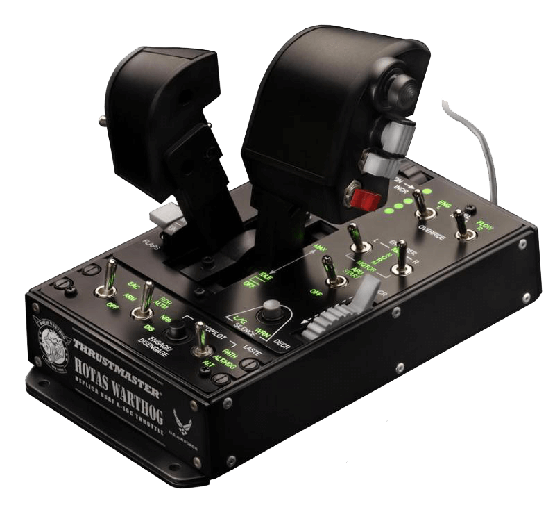
It has a number of silver switches, which fall into three different categories:
- Normal 2-position switches. When the switch is in one of these two positions, it sends a perpetually “held” button press, and while it’s in the other position, it sends no button press at all. The EAC on/off switch on the Warthog is an example of this.
- Normal 3-position switches, which send no button press in the center position, but send a perpetual “hold” for two different buttons in the up and down states. The autopilot switch on the Warthog is an example.
- Special 3-position switches which send a normal (momentary) button press in one direction (you have to keep holding the switch for it to continue sending the button press), no button press in the center, and a continuous button press when they “lock” into the third state. The engine toggles on the Warthog are like this: “ignition” is momentary, “normal” is center, and “motor” is the toggle-and-hold.
X-Plane 11.10 provides two .joy annotations to handle all three of the above cases: “momentary” and “virtual” buttons. When a button is marked as momentary, X-Plane will only run the associated command on the initial down-press, rather than running the command continuously for as long as the button is “down.” Likewise, “virtual” buttons are triggered when a “real” button (i.e., a button that you see in the UI when you have no .joy configuration file) is pressed or released—you pick which.
Here’s how it works in the above 3 cases:
The 2-position switch
This requires an immediate press-and-release when the “button” goes “down,” rather than firing the associated command continuously as long as the switch is in that state. Likewise, it requires a press-and-release when the “button” is “released (i.e., when the switch transitions to the “off” state).
The solution: mark the “button” as momentary, and create a new virtual button that fires on the release of the “button.” Example:
Button 15: Momentary
Virtual Button 100: Release Button 15
Note that this creates a new button at index 100—make sure you don’t actually have 100 physical buttons, or your newly created virtual button won’t work. In the rest of the file, you can refer to “Button 100” as though it were perfectly normal—you can map it to a view, assign a default command to it, etc.
The 3-position switch
This requires a single press-and-release when the two “buttons” are “pressed” initially, and it requires a separate command (for the center state) when either “button” is released.
The solution: mark the two “buttons” as momentary, and create a new virtual button that fires when either button is released. Example:
Button 12: Momentary
Button 13: Momentary
Virtual Button 105: Release Button 12, Release Button 13
The “special” 3-position switch
In this case, one of the button presses can actually be left alone—since it already behaves like a normal, momentary button, it doesn’t require any special configuration in the .joy file.
To cope with the “locked” button press, we need to once again mark it as momentary, and for the third state (which sends no button press at all), we need to create a virtual button that fires when either “button” is released. Example:
Button 18: Momentary
Virtual Button 105: Release Button 18, Release Button 31
In the case of our example Warthog above, all the states for one switch exist in the same space on the joystick. This can be problematic when you try to map two, three or even more of these switch states to very similar coordinates on your device image. The solution to this is a “Button Group:”
Button Group ([display name]): [button #] [button #]
Button # ([display name]): [x coordinate in the image] [y coordinate in the image]
Button # ([display name]): [x coordinate in the image] [y coordinate in the image]
You can specify the buttons to group together in any order. The first coordinates listed are used to position the image labels, but we recommend giving the same coordinates to all buttons in the group just for the sake of clarity.
Example:
Button Group (3-way Switch): 104 102 103
Button 102 (↑): 100 200
Button 104 (Center): 100 200
Button 103 (↓): 100 200
New capabilities in X-Plane 11.20
“Configuration Groups” allow you to group axes and buttons together. Note that X-Plane does not differentiate between configuration group types, so each must have a unique number. Example:
Configuration Group 2 ([display name]): Axis 2 3 Button 12
“Exclusive Configuration Group” is designed for hardware like the PS3 controller, where every button is also an axis. You specify the axis and the button, and the user has to choose in the UI which to use (and X-Plane will ignore the other). Example:
Exclusive Configuration Group 3 ([display name]): Axis 10 Button 4
New ways to use axes
Self-centering axes operating as linear axes
If you assign a self-centering axis to a linear axis assignment, we use the deltas from centered to move the throttle in that direction; a big movement from centered gives you a big jump in the axis position, etc.
For example, if you assign the Y of your X/Y stick to throttle, instead of the centered position always sticking your throttle at 50%, it instead leaves the throttle alone. You push the axis forward a bit, the throttle goes up (and remains there when you bring the axis back to center). Pull the axis back a bit and the throttle will go down. It requires some hint to us in the .joy file about the type of axis. A device with no .joy file at all will not work. To see it in action, you’ll need a .joy file with one of the following:
- an explicit axis type line in the assignments section
- a default assignment that would require a centered axis (pitch/roll/yaw/etc.)
Example:
Axis [axis index]: joy_use_roll
Axis [axis index] Type: centerable
Changing a device with no .joy file from pitch to something else can’t do it, because you may have accidentally set a linear slider to pitch at some point.
Axes operating as commands
In the .joy file, specify the axis type as either linear or centerable. Then, in the X-Plane axis usage dropdown choose “Custom commands” and you can assign some number of commands (based on the type of axis) to be fired as you move the stick:
- Linear axes always have 2 configurable slots, self-centering axes always have 4.
- You can assign up to that number of different commands to each slot.
- The assignments in each slot get triggered when you move the axis into a certain range of the stick. (E.g., slot 1 on a linear axis is from about 0 to 50%, slot 2 is from 50 to 100%.)
Axes operating as hat switches
When you have a 2-axis group specified in the .joy file as described above, you’ll get a toggle in the UI next to the group’s name to choose “axis” or “hat switch” mode.
Handling VR controllers
“Reserved Configuration Groups” are specified the same way as the configuration groups as above, but the default config is all-or-nothing. This was designed for VR, where we want the stick+clicker to either all be for menu manipulation, or to totally disallow a partial menu manipulation config (i.e., you can’t set the X/Y to pitch & roll, but keep the clicker to be “menu enter”). Example:
Reserved Configuration Group 1 ([display name]): Axis 0 1 Button 3
Automatic calibration can be specified to bypass all calibration in X-Plane. All axes on the device must be specified as such. Example:
Axis 2 Calibration: auto
X-Plane also checks for and complains at you if you don’t have the required VR assignments (VR X/Y axes plus VR menu enter command) mapped to any VR controller.
New capabilities in X-Plane 12.00
Mark an axis as control-loaded for trim
If an axis is control-loaded instead of spring-entering, its “center” is decided by the control loading software rather than a fixed position. To keep X-Plane from adding trim onto the already trimmed position of the axis, mark an axis that centers itself by force feed back with the tag “ffb”, like so:
Axis [axis index]: [joy use] ffb
I’m having a trouble with MadCatz SURFR controller with X-Plane since XP Ver 11.20 or so. This controller is connected with Bluetooth. XP detects this controller, but none of joystick axis moves nor any of HAT buttons detected. Built-in keybord seems to work fine. This controller is fully working under Win10 x64 game controller control panel.
I’m using XP V11.30 Final on Latest Win10 x64 build as of 01-17-2019.
After looking at property information on this controller, I noticed in addition to the VID & PID, there is a column (Col) ID is associated device to determine the keyboard portion and joystick portion. How do I assign the column ID in my .joy file ?
I tried the demo of version 11 and am in the unfortunate position of not being able to use Version 11 because my graphics adapter will not sustain an appropriate FPS, even at the lowest possible rendering settings. I have tried version 10 and the demo runs OK at fairly low rendering settings, so I am going to purchase version 10. I know it would be better to replace the graphics card with one with more power but I am a 81 year old USMC vet with a handicap that prevents me from installing a graphics card. In addition, moving to Windows 10 would create an enormous application migration for me as I have 86 applications that I need to use for audio restoration and video editing that I use for creating entertainment for vets at the local veterans home here in central New Jersey. Thus I am working with your Mr. Thomson on purchasing version 10.
My System is as follows:
• Intel Xtreme I9, 6 dual 3.47 GHZ Processors 12 individual
• Logitech X56 rhino HOTAS stick and throttle
• Windows 7 Pro, 64 bit, SP1
• Direct X 11
• 12 GB Memory
• ATI FirePro V5800 V graphics card, Driver Date 1/18/2017, Version 15.201.2401.1009
• 2 solid state disks, 120GB, 240GB
• 2 Dell 27″ Monitors DVI attached, resolution, 2560×1440, Dell-U2700
• 12 USB 2.0 ports
Is there a similar document available for version 10 and the x56.
My biggest quandary is that the x56 manual has a set of instructions for mapping and the version 10 appears to have another
Thank You In Advance,
Henry
Sorry to be the bearer of bad news, but… the fancy visual joystick configuration is a new feature to X-Plane 11; there’s no corresponding feature in X-Plane 10 (and thus no .joy file spec). As far as X-Plane 10 is concerned, all joystick are the same: just a collection of buttons and axes.
Hi Tyler,
I managed to produce a .joy file for the T.16000M joystick under Linux. This joystick lacks support in this platform. Is it possible to submit the file I made somewhere so that others can have this working out of the box?
All the best,
Felipe
Sure—email it to me at [my first name] at x-plane.com.
Hi Tyler,
Just to make sure, did you receive my e-mail back then?
Best,
Felipe
I recently purchased X Plane 11 and have had the Saitek/Logitech x56 stick/throttle for more than a year. It has configured normally for other Flight sims but for Xplane the Throttle configs perfectly but the Joystick’s movements are not registering. The buttons on the stick register fine but LR FB (basically any movement of the stick itself) are not registering. Any advice??
This is a bit off topic, but essential in terms of plugin management of certain functions related to joystick axis assignments.
The SDK documentation does not currently publish the enumeration of all of the possible joystick assignments as far as I can tell, nor are they exposed in the SDK C headers. Some enterprising developers have deduced this list – which I’m posting here for validation.
Is this correct? Is it complete? Thanks for any help – it would be nice to have this from an official source.
Enum Axis
0 pitch
1 roll
2 yaw
3 throttle
4 collective
5 left toe brake
6 right toe brake
7 prop mixture
8 carb heat
9 flaps
10 thrust vector
11 wing sweep
12 speed brakes
13 displacement
14 reverse
15 elev trim
16 ailn trim
17 rudd trim
18 throttle 1
19 throttle 2
20 throttle 3
21 throttle 4
22 prop 1
23 prop 2
24 prop 3
25 prop 4
26 mixture 1
27 mixture 2
28 mixture 3
29 mixture 4
30 reverse 1
31 reverse 2
32 reverse 3
33 reverse 4
34 landing gear
35 nosewheel tiller
36 backup throttle
37 auto roll
38 auto pitch
39 view left/right
40 view up/down
41 view zoom
FYI: Based on some experimentation of my own, this enum list does not appear to be correct.
Hi,
The following doesn’t even appear on my Joystick settings screen –
“Save as Default for [device]” button there on the joystick configuration screen.”
I’m still struggling to have the images of my X52 Pro joystick and throttle appear in the set up.
Would appreciate any further suggestions.
Kind regards
Hello Tyler
I am trying to understand how to use a 2-way switch for nav lights as you explained. I use as example a physical SPST off-on switch (two physical contacts). It shows up in Windows Devices as 1 button. Is then the following code correct:
Button 15: Momentary
Virtual Button 100: Release Button 15
Button 15 : sim/lights/nav_lights_on
Button 100 : sim/lights/nav_lights_off
Thanks for the help
Hi Tyler,
I’m trying to get various toggle switches in my custom made switch panel working. I manually edited my “Switch_Panel.joy” file using the same code to what Jozef created (submitted on Sept 21, 1019) but when I launch X-Plane, the “virtual” button doesn’t work and both the log.txt file and the joystick configuration utility show no sign of a “new” virtual button in either list.
All toggle switches are of the type “2-pin SPST”. Here’s the code I’m using to control the Avionics toggle switch:
Button 7: Momentary
Virtual Button 107: Release Button 7
Button 7: sim/systems/avionics_on
Button 107: sim/systems/avionics_off
I have a total of 15 toggle switches in my custom switch panel. If you could provide a sample of the code necessary to get the avionics switch working properly, then I can duplicate it for the remaining switches.
Please help.
Brian
Hi Tyler,
I’m trying to use a centerable axis as linear to control throttle, just as you describe in the text. However I’m having trouble following the full logic flow. I create my .joy file and modified the Assignments section as such:
Axis 1: joy_use_thro
Axis 1 Type: centerable
This doesn’t seem to behave any differently than standard config, meaning the throttle position matches the axis position (leaving it centered gives me ~35% throttle). What am I doing wrong? Thanks!
That should be all you need. If you’ll send me your complete .joy file (my email is my first name @x-plane.com) I can take a look. 🙂
hi just a note that the url to the Easy Imagemap Generator tool. is now 404’d
Hi, I am enjoying Xplane11 very much. But there is a problem with a hardware. I have a Cockpit For You(CFY) throttle quadrant which is connected by the ethernet.
Xplane11 does not recognize the Cockpit For You(CFY) throttle quadrant as a joystick. As a result, the throttle quadrant is not working properly including the autothrottle functions and button mapping.
Many users using a Cockpit For You(CFY) throttle quadrant really wish to solve this problem(See https://forums.x-plane.org/index.php?/forums/topic/190719-cockpitforyou-cfy-hardware-with-the-zibo-mod/).
Please make recognize the ethernet hardware. Thanks!
X-Plane only natively supports USB hardware (and a couple old serial devices). We have no plans to try to support ethernet-connected hardware—you’ll need to go to the manufacturer for that.
Hi!
I installed the 11.50 beta additionally to the current non-beta and moved the complete keyboard presets and joystick configs to the new beta resources folder. Unfortunately it says now “uncalibrated joysticks” (Sidewinder and CH throttle quadrant) and doesn’t find my custom profile, no buttons assigned). Neither can I find an option in the old version to somehow export or “save as default” in the settings. What am I doing wrong here?
I’ve added a second Saitek Throttle Quadrant to my rig and I’d like to be able to differentiate between the two devices by name in the UI so that I don’t inadvertently remap the wrong device between profiles. Is this possible?
Hi FlyGuys(and Galls!),
I have full switchgear on my Douglas DC3/C-47 rig.
I’ve wired up my DC-3 magneto switch but of course its not working properly. On real aircraft the mag switch runs on a live circuit with the Left, Right and Both settings switching to break the circuit. XP of course works it seems the opposite way and I cant get the sim to sense the “Both” setting on the mags.
To make more clear – (on just one of the engines- for clarity)
I program the following
Click switch to right mag = Button 10 is highlighted and action confirmed as “Right Magneto”
Click switch to left mag = Button 11 is highlighted and action confirmed as “Left Magneto”
Click switch to Off = button 10 “Right Magneto” AND button 11 “Left Magneto” will be highlighted.
Click switch to Both = and no buttons will be highlighted.
I have tried opening the program with the switches in the “Both” position and the “Off” position to no avail.
What line do I change to make this work in the correct sense ?
sorry – should read “live circuit with the Left, Right and Off settings switching to break the circuit”…..
Hi, I am having trouble with the virtual buttons. I am building a homemade custom cockpit, and for the buttons I am using the Leobodnar BBI-64 Button Box Interface. X-plane registers the button presses, no problem there. I am using on-off switches, so I made the change in the .joy file to make them momentary switches, this also works. But I am unable to get the Virtual buttons working. They dont show up in the joystick settings menu so I can assign commands to them, and when I try assigning commands manually in the .joy file nothing happens. Here is an example from my file:
Button 27: Momentary
Button 33: Momentary
Virtual Button 127: Release Button 27
Virtual Button 133: Release Button 33
Button 127: sim/flight_controls/landing_gear_down
Button 133: sim/lights/strobe_lights_off
What am I doing wrong? I have checked the log for errors and could not find any. The log shows X-Plane only adding the 64 physical button indexes
I am using X-Plane 11.50r3, windows 10.
Really hope someone can help me 🙂
Hello Tyler,
I have succesfully created a default joystick configuration file for a BU0836 interface, modified that file by changing a few buttons to momentary ones and saved it. However there seems to be no way make Xplane to load that modified file as a default file for the BU0836. I must be missing something? Please advice.
Hi!
How to implement more than 1 View section and designat a image file to that?
Example:
This section already exists:
View: Front
———————————————————————–
Image: MacBare Yoke 3.png
I want implement the section “Other Control”:
View: Other Control
———————————————————————–
Image: MacBare Yoke 4.png
This is the correct way?
“Other Controls” is created by X-Plane automatically if any buttons or axes aren’t either assigned or marked hidden in the .joy file. We do not recommend creating this section manually.
I also recommend checking out the .joy files that ship with X-Plane for examples of how to specify images.
I’ve done profile for VKB Gladiator NXT. But with departin of Tyler from the team, what e-mail should i use to sending png+joy files?
Please zip & send new files through the X-Plane Support form here:
https://www.x-plane.com/support/
Then they will get forwarded to the right person!
Hi, thanks for this detailed instructions.
I just purchased a Logitech X52 Pro HOTAS. It comes with 3 modes and a shift button. But X-plane interprets the modes and shift buttons as normal buttons. So I can assign a function to it, but I cannot change the function another button does when pressing the shift or changing the mode.
I found a LUA script that allows one to code it, but I was wondering if is there a way to do that on the Joystick config file.
Linux mint20, X-Plane 11.55: Hello, i have a new joy config with bitmaps, working axes and buttons. The joystick is the Thrustmaster Airbus quadrant with the Airbus Addon. but two axes are reversed.
Throttle 2 is moving the flaps axis in sim and the speedbreak axis is moving the throttle 2 axis in sim. What do I have to look for in order to change the axis assignment, where could the error be ? Thanks for help. Or is it much easier to have the windows config in use and change some axis ?
You find it in settings. Can change buttons and axis to whaterver you like.
Hi there!
Trying to get my Logitech X52 pro set up. Its not giving me a default setting, could you please advice what i should do? and if there is a tutorial on how to set it up in a certain recommended way.
best regards
Kal
Hi folks.
I cannot get X-Plane to recognize my Thrustmaster TFRP rudder pedals under Linux MInt. There does not seem to be a *-linux.joy config file. I took a shot at making one by modifying the windows.joy file. No goodness for me. The system sees the hardware:
Device-1: 1-3.1:4 info: ThrustMaster T-Rudder type: HID driver: hid-generic,usbhid
rev: 1.0 chip ID: 044f:b679
May I submit the errant file and ask one of you to tell me where I went wrong? Seems this should be possible. Thanks.
Olá amigos,
Comprei esses dias um joystick xbox one original, mas o x-plane 11 não o reconhece, na pasta joystick config até tem o arquivo “Xbox One Controller – Windows.joy” e não funciona, ele simplesmente ignora, existe algo que possa ser feito, para que possa ser reconhecido?
I’m trying to connect a GoFlight MCPPro. The manufacturer, in their operations manual (some time ago) suggests that “X-Plane contains built-in support for GoFlight’s GF-45, GF-45PM, GF-P8, GF-T8 and GF-LGT cockpit control modules”.
Might this still be the case? If so, I’ve been unsuccessful in all my efforts to configure it.
I am currently trying to interface with a small program called XPGF with a small amount of success. This is stymied by changes to naming of DataRefs.
Any advice would be greatly appreciated.
Kevin,
A payware interface called Goflight Interface Tool was just updated for XP12. It’s from Polypot software for a nominal fee.
I can’t see save option for my joystick/throttle, only reset to defaults (XP11 & XP12).
What should I do to save defaults?
Hi all!
I would like to know why X-Plane, even in version 12, does not allow 2 different flight controls to associate the same command. For example: I have a SAITEK PRO FLIGHT SYSTEM flight controller and another Thrustmaster T.Flight HOTAS X flight controller and it is not possible to configure the Throttle command on both controls, X-Plane displays a message that there is a conflict in the command and enables the command on only one of the controls. In flight simulators FSX, FSX-SE, Prepar3D it is possible to do this smoothly, without any problem of conflicts.
Is there any solution to solve this situation or has no one ever had this kind of problem?
Thank you so much!