X-Plane 11.30 introduces new facades and objects for the creation of embankments, sea-walls, piers, and docks. These can be found in the WED library hierarchy at: “lib/constructions/piers“.
Key components are special facades with various wall types for specific usage (similar to the ‘Terminal kit’ introduced in an earlier release). This facade is used in the main for the creation of ship ports, quays, river banks and sea-walls.
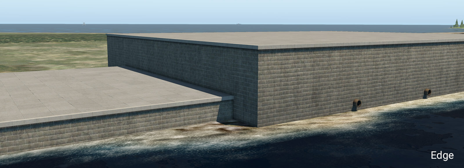
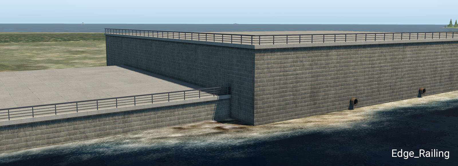
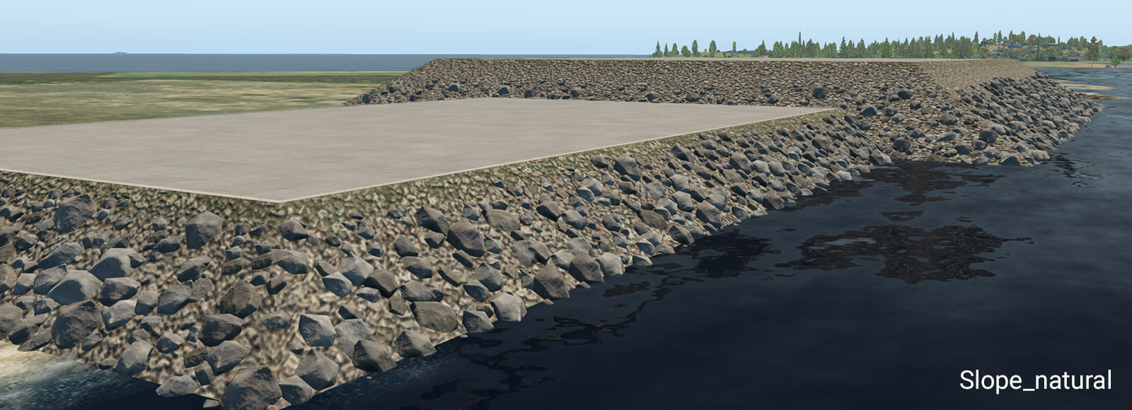
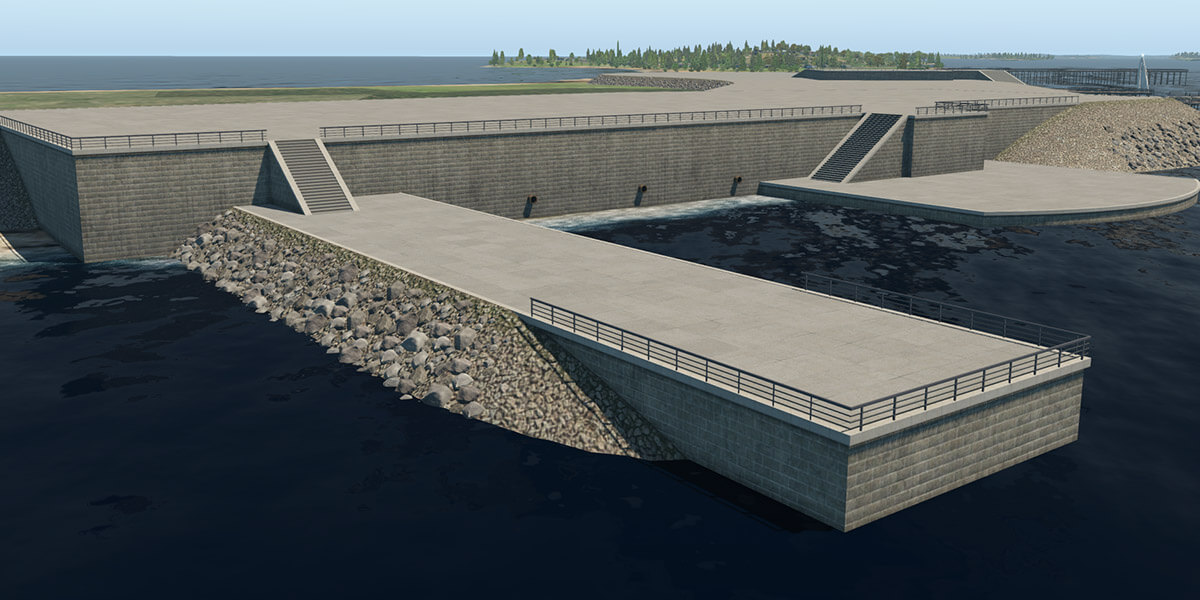
embankment_01.fac
This facade can form a typical stone embankment with vertical and sloped walls. It is designed for height ranges between one and ten meters, with a one-meter step. This facade must be placed as a closed polygon, with manually selected walls. Due to the nature of the facade system, there are some design limitations. The basic vertical wall works without any specific limitations. However, sloped walls (like natural slope, stairs or ramp) don’t work very well in conjunction with sharp angles at corners. When the corner angle is 90 degrees and more, there is an obvious distortion in UV texture mapping. This may look silly, especially with the greater height so try to avoid very sharp corner angles when using these walls. For the same reason, it is not recommended to switch between vertical and sloped walls at corners. This works best with straight polygon segments.
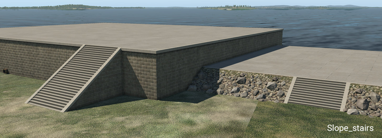
Stairs have exactly the same angle as the natural slope so they can be seamlessly placed in between sloped walls.
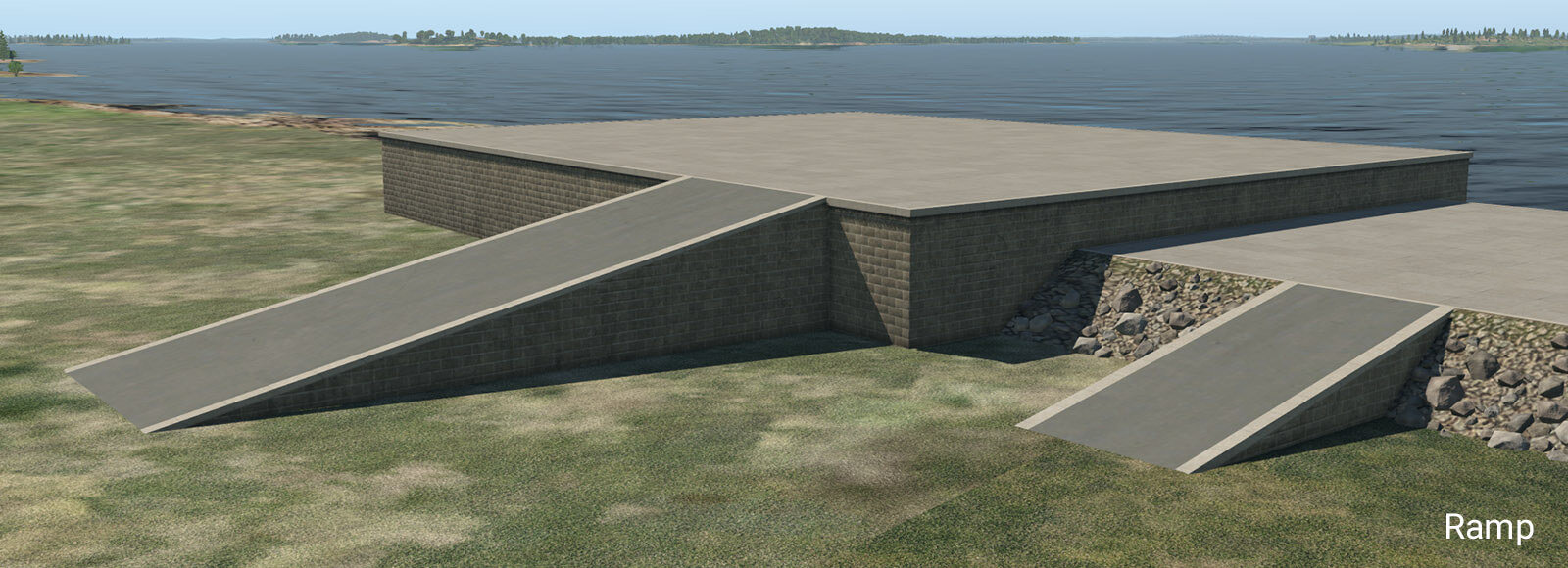
The ramp is designed for straight segments. Do not use it at sharp corners, because it has very obvious UV texture deformations due to its shape.
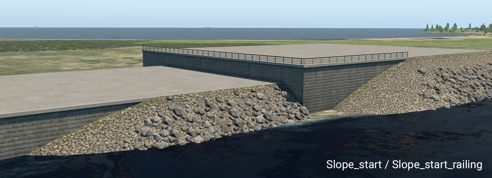
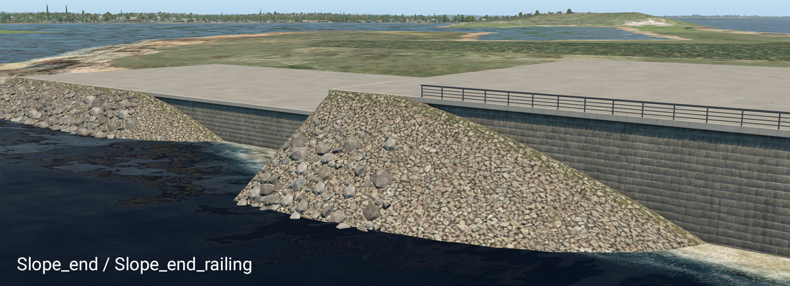
These pairs of transition segments are useful when you need a smooth transition between the vertical wall and natural slope. They work best in straight segments also. Note they require some length to be shown properly. A safe length is about 32 meters. However, you can make the transition segment much longer. If you do so, “Slope_start” will appear at the very beginning of that segment, and “Slope_end” will appear at the very end.
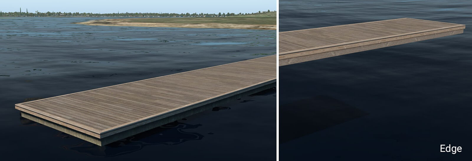
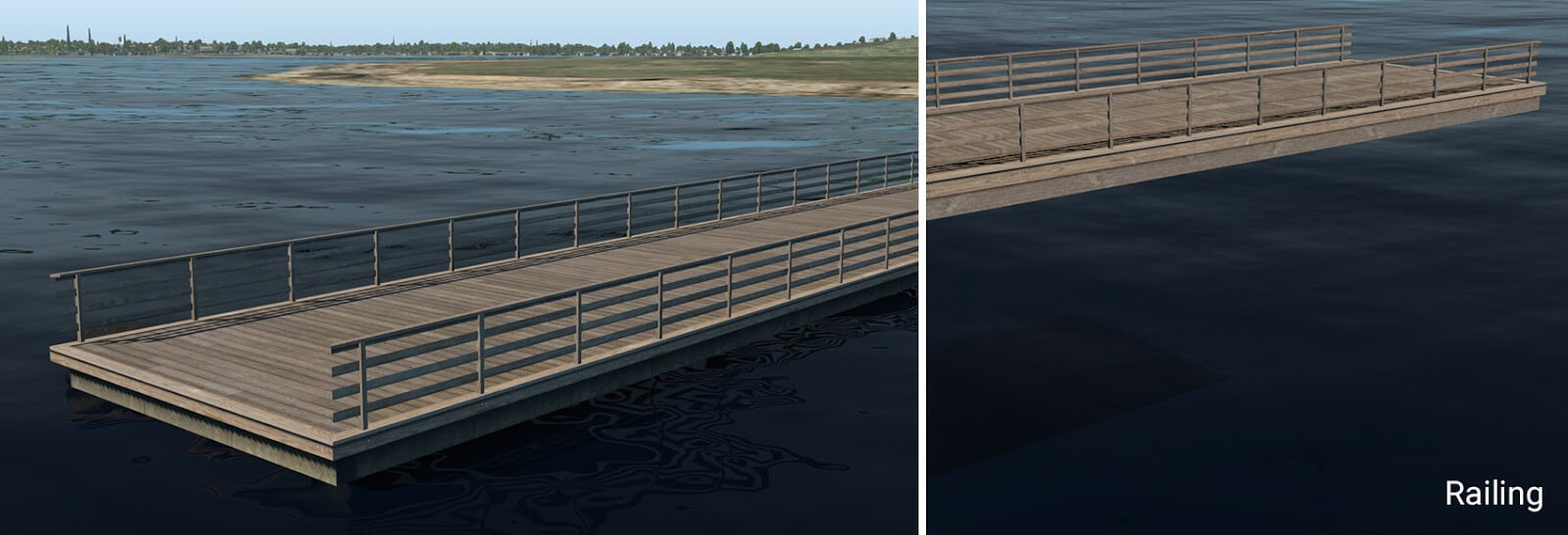
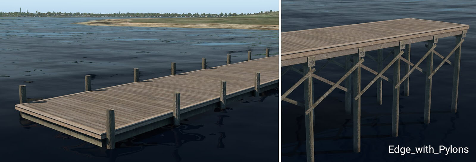
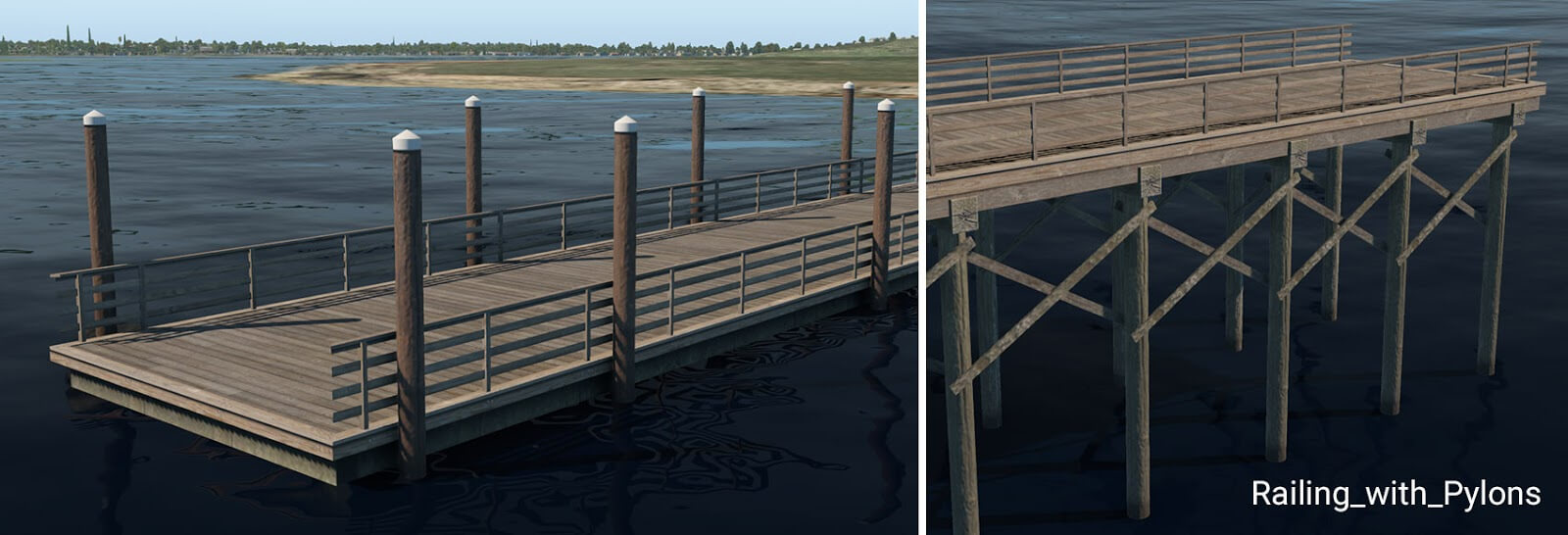
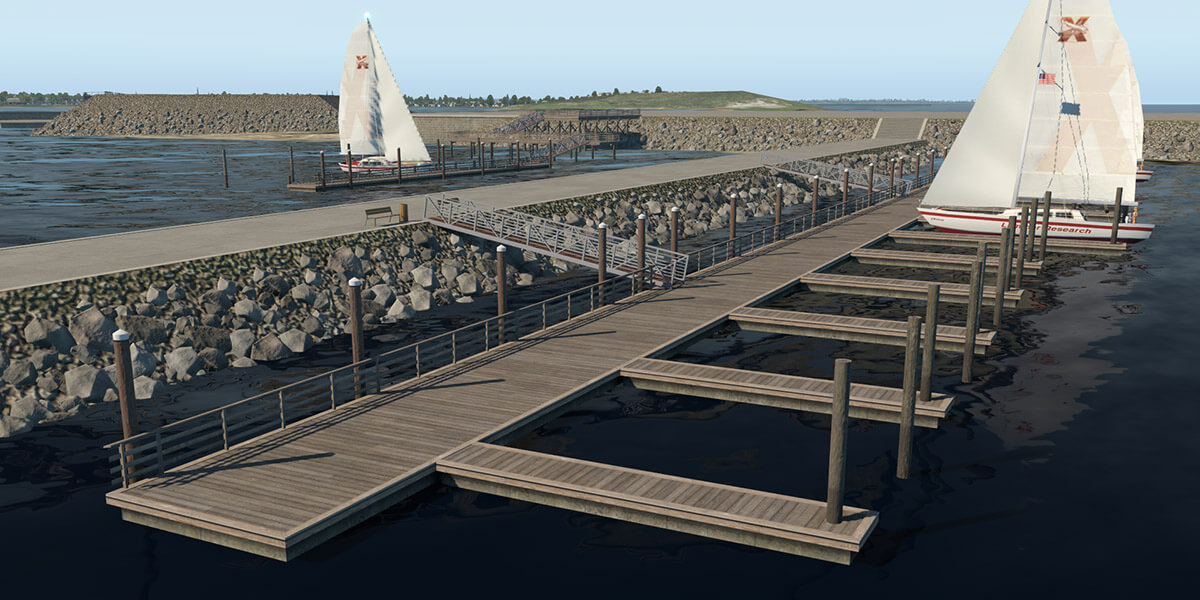
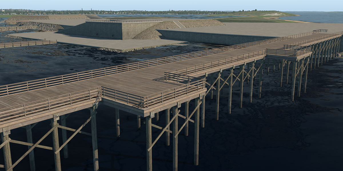
pier_wooden_01.fac
This facade is used in the main for the creation of typical wooden piers or docks. It works for the same height ranges (1 to 10) plus an additional 0.6 meters. This is because 60 cm is a typical height for small floating piers. The two lowest height levels (0.6 and 1 meter) look like a floating pier and the rest form a pier on pylons.
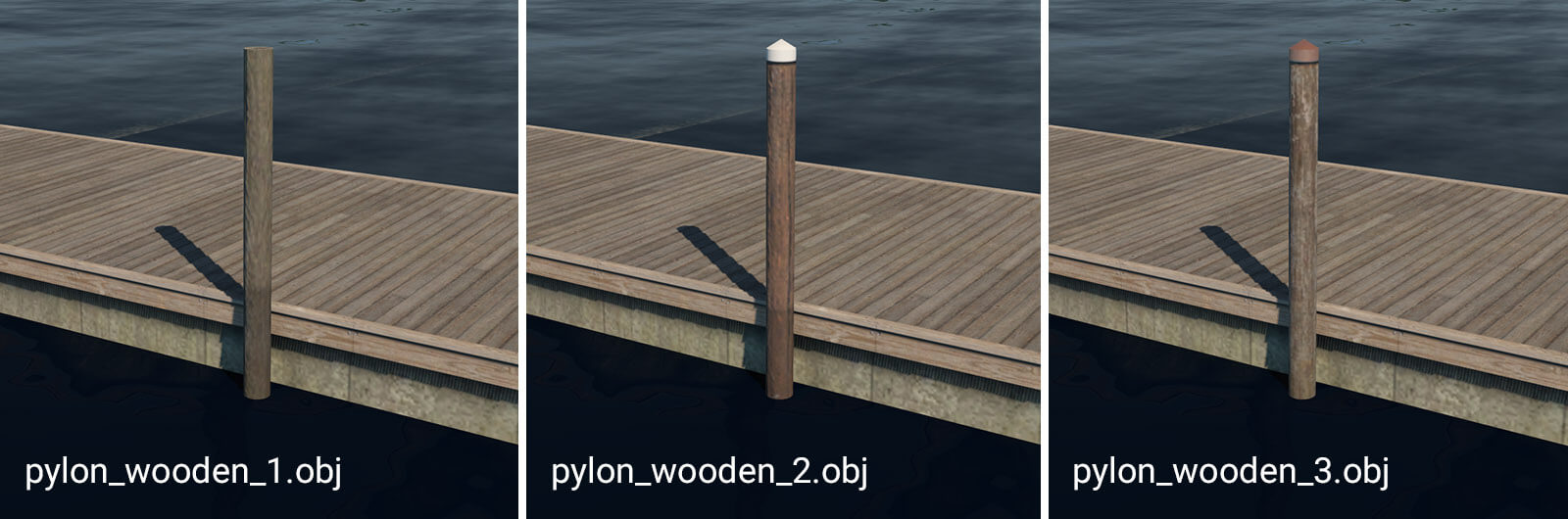
pylon_wooden_X.obj
These pylons can be placed manually. They are useful in combination with floating wooden piers. For more convenient placement, they are also available as strings: “pylons_row_wooden_X.str”.
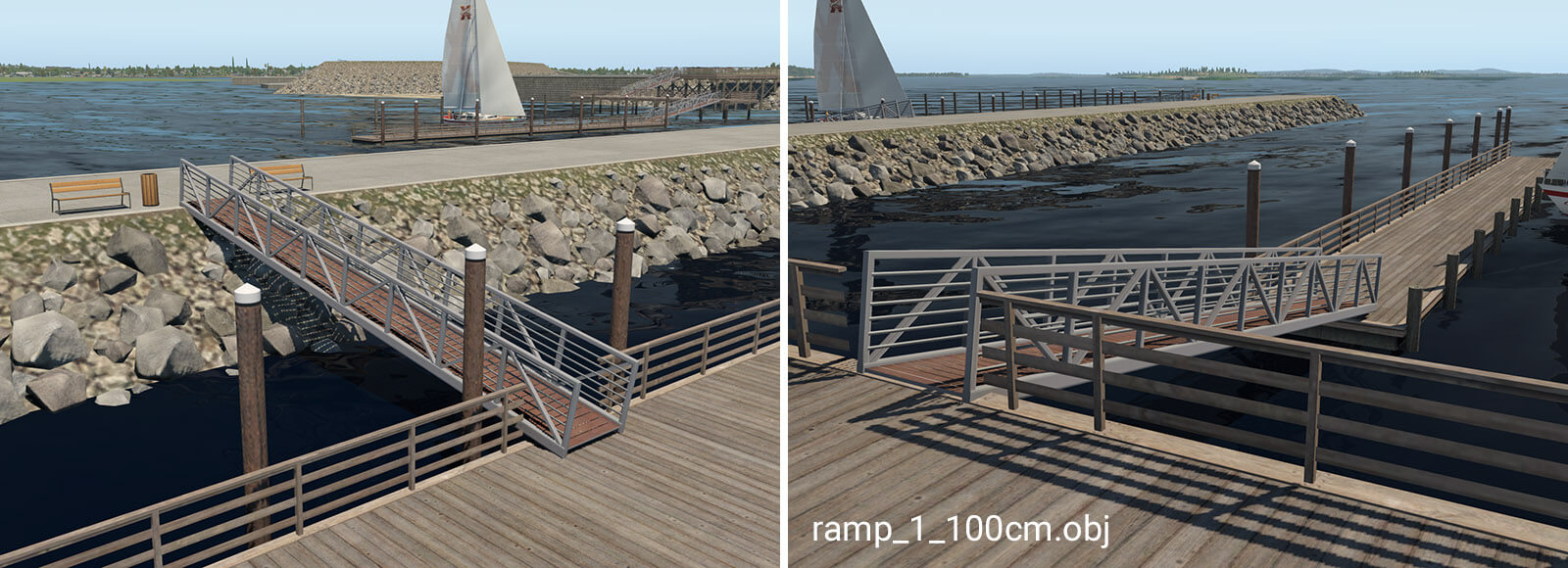
ramp_1_100cm.obj
The ramp object is available in seven different variants. It is designed for connections between levels with differing heights. The numbers in the name mean the total height of the ramp (e.g. ramp_1_240cm is 2.4 meters high). This object is available with heights of 140, 240 and 340 which is necessary in conjunction with the special 60cm pier. For proper placement of the ramp above the pier, artists must use the ‘Set MSL’ feature in WED, with the appropriate altitude above sea level.
Sample constructs:
Excellent addition for us scenery designers this will significantly improve the fidelity of coastline airports.
I note that you are requiring the use of MSL to place the ramp above the pier correctly, but the elevation of an object above the actual ground depends on the mesh, which can be changed.
This isn’t a problem in the sea, as it’s reliably at 0 MSL (though if you ever plan to implement tides, perhaps not…) but if these objects are used on lakes or inland seas the MSL may be very far from zero.
Are there any plans to introduce an ‘AGL’ object elevation placement ATTR, as it would be very widely useful for object elevation placement, reliable and much less awkward?
Does the pier_wooden_01.fac auto generate the pylons? I have tried every combination and do not get them to show. The railings show but not the pylons.
I am fairly new to WED and scenery development. Not able to find much discussion around the embankment and piers added into WED. I have been designing piers in Northern California Monterey Bay. I have modeled the Santa Cruz and Capitola piers. I find setting the platform elevation difficult as the facade height is affected by some other scenery component. For example, when modeling the pier to connect to land at a point further inland the the surf edge, and setting the height to 1, it does not place the platform “floating on the water”. It remains several feet above the water, however, the autogenerated pylons are short and not actually in the water. Changing the height actually causes the pylons to lengthen into the water. Somewhere around height 5 or 6, it starts lifting the platform out of the water. I thought maybe it was somehow affected by the default ground level but when I placed a pier in another location, it had no problem melding with the sand on the beach. Another problem is that .agp elements cannot be set above sea level even though the MSL value was set well above sea level. Same condition when setting the AGL. Trying to populate a usually very crowded parking lot on the Santa Cruz pier can only be done using individual vehicle object. Time consuming. If anyone has any thoughts on what I’m doing wrong, I’d appreciate hearing from you.
Thanks