Weather Radar for X-Plane 12.3
General
Beginning with X-Plane 12.3+, there is a new Weather (WX) radar display with advanced behaviors available to aircraft authors. The old, legacy composite WX display is still available as well. The new display is available in two forms. For aircraft authors, the first form is displayed via the regular EFIS map instruments found in PlaneMaker's instrument library. For plugin authors, the second form is via a 2D RGBA return-strength texture, which provides radar return strength values in the 8-bit RED channel of the texture, from which plugin authors can read these values and render their own wx displays. Other channels in the return-strength texture are not currently used.
The radar display on X-Plane’s EFIS maps is rendered to a 24bit RGB image using a generic color stripe texture. (Resources\bitmaps\world\maps\RADAR.png). No particular effort is made to make the radar look like any specific make and model, but rather is made generically plausible to NEXRAD / FAA standards. You can customize this texture for your specific aircraft if you like by duplicating the stripe texture into a EFIS subfolder in your aircraft’s cockpit folder (not cockpit_3d) and modifying it.
About Aircraft Radar
Aircraft radar systems typically consist of a single antenna, a Processing CPU, a graphical display and various mode controls. The antenna scans a Sector Arc within the antenna’s Sweep Arc at a rate called the Scan Rate, and receives return signals which are processed and shown on a WX Display in the cockpit. The WX display screens are updated at a rate called the Refresh Rate, which most of the time, is the same as the Scan Rate, but not always. (more below)
The Sweep Arc is the maximum arc range the antenna can physically traverse, whereas the Sector Arc is the arc range actively being scanned. Most of the time, the Sector Arc = Sweep Arc for generic scanning; however, some systems have the ability to narrow the Sector Arc, in order to achieve a higher scan rate in a particular direction. The video below shows an antenna moving through its Sweep Arc.
<future image of radar_sweep in new docs>
Many radar systems have antenna that can tilt up/down over a small range of angles. In simple systems, this tilt angle is manually controlled by the pilot (Manual-Tilt). In slightly more sophisticated systems, the tilt-angle can also be adjusted up or down automatically based on other factors such as pitch attitude, altitude, range settings, etc. (Auto-Tilt). In even more sophisticated systems, the antenna can automatically scan at multiple tilt angles and use those multiple scans to generate a single composite image to display to the pilots (Buffering Types). The video below shows an antenna scanning through multiple tilt angles in such a mode.
<future image of multi-scan opt in new docs>
GA aircraft usually have one WX display whereas Transport Category Aircraft requiring two pilots commonly have two WX displays, one for each pilot. When two WX displays exist, one for each pilot, then each display may have its own set of controls, and when the tilt angles for each side differ, then the radar antenna is “time shared” between the displays and the Refresh Rate on each WX display then becomes <u>half</u> of the antenna Scan Rate. X-Plane can simulate Manual-Tilt, Auto-Tilt, Multi-Scanning and time shared antenna behaviors, as well as many other modes.
PlaneMaker Settings
To implement the new radar, you will need PlaneMaker 12.3.+ There are three configuration settings, located in the Standard Menu > Viewpoint > General Tab > Map Panel as shown below.
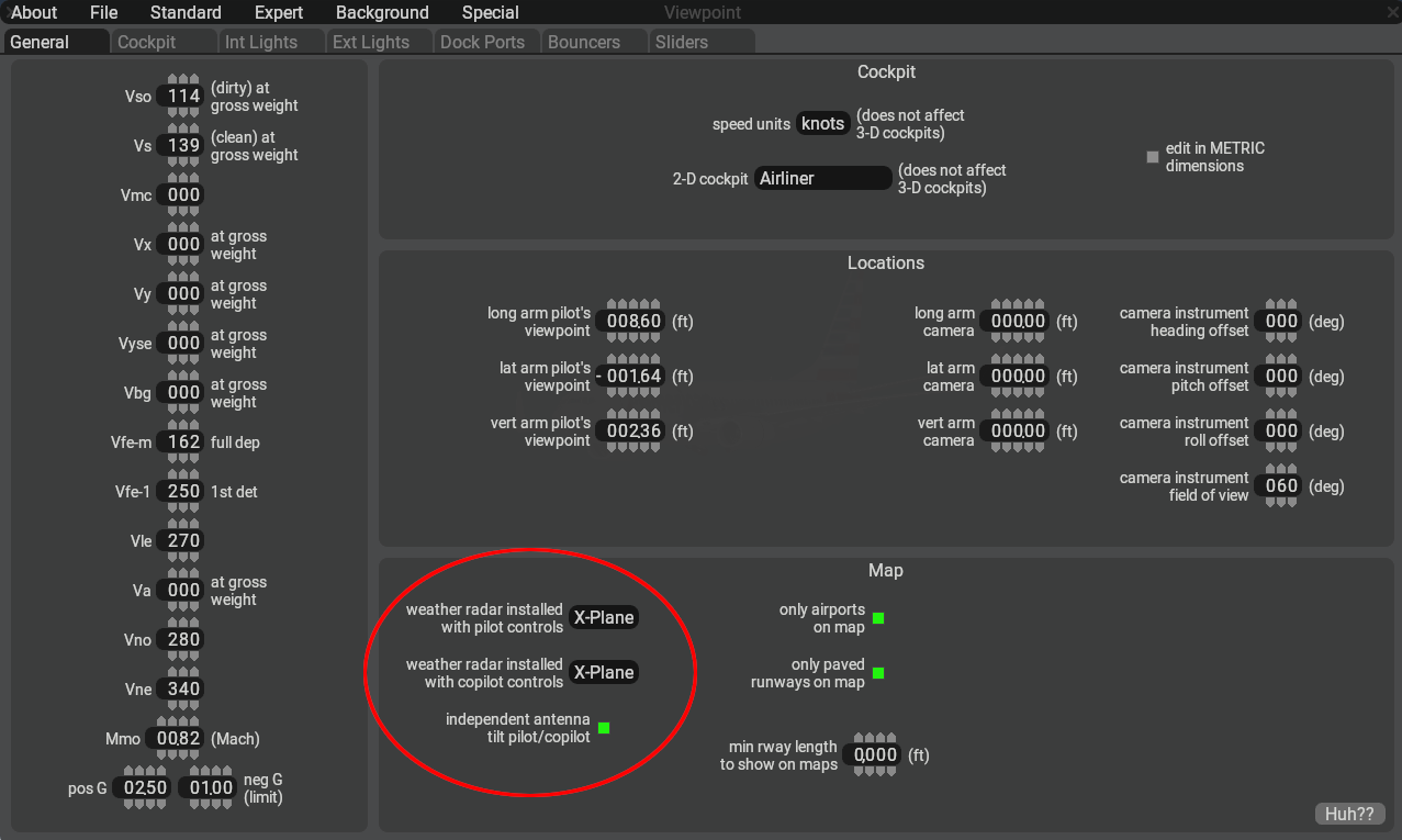
Each of the two pulldown menus contain the following three options:
| Option | Description |
|---|---|
| None | Legacy radar image used on EFIS map instruments. |
| X-Plane | New radar image used on EFIS maps instruments. (using new controls/DRs/commands) |
| Plugin | Radar emission “return strength” values are provided via a 8-bit grayscale texture for plugins to query. (The grayscale texture may be viewed on the PM EFIS instruments.) |
When both the pilot and copilot pulldowns are set to ‘X-Plane’, then a checkbox for independent antenna tilt will become available, otherwise it will be hidden. As mentioned above, when this option is enabled and the pilot/copilot tilt control settings differ, then the single antenna will be time shared between the radar controls. When this option is not checked, then both WX displays will use the same tilt value. Any input on either side will be copied to the opposite side.
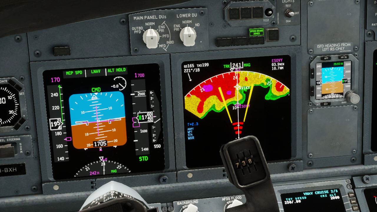
The WX radar image is rendered on PlaneMaker's EFIS map instruments as shown below. These instruments can depict either weather or EGPWS terrain depending upon the EFIS control settings. WXR and EGPWS TERR modes (described further below) are mutually exclusive and cannot be displayed at the same time.
> NOTE: If you need EGPWS functionality, then this requires a GPS FMS instrument to be present on the 2D or 3D panel for X-Plane to load the terrain database. If your panel texture space is limited, you can use one of the screen only GPS FMS instrument options and scale it down via its Size parameter so it takes up very little texture space.

> If only WX Data is desired, with no map overlays, such as would be the case for an older, dedicated WX Display unit like a Collins IND-300 or Bendix RDS-81, then you should use the basemap_s_HM.png instrument. This instrument only displays Weather or Terrain data exclusively and is suitable for overlaying other generic or plugin generated graphics.
Plug-In Customizations
For those desiring to craft their own WX display graphics and having selected the PlugIn pulldown option in PlaneMaker, the virtual radar return strength values are written into the 8-bit RED channel of a 32-bit RGBA texture (GBA channels not used). The 8-bit value at every point represents the strength of the radar return on a scale of 0 to 255. A plugin can use this texture data to further generate and render a color grading exactly representing a particular model of radar.
The plugin can either draw to the panel texture (legacy method), or draw to an FBO of a custom avionics device using the XPLMAvionics API, which is the preferred method for plugin EFIS graphics since X-Plane 12.1. Via the XPLM Avionics draw callback, a plugin can call the XPLMGetTexture() function with the enum values xplm_Tex_Radar_Pilot or xplm_Tex_Radar_Copilot to access the texture values for subsequent graphics customization.
Operating Mode Descriptions
Before getting into the Datarefs and Commands sections below, it is helpful to discuss the various Operating Modes that Radars can employ. The table below lists all the modes available to simulate Radars of varying complexity. The modes you implement will depend upon the model of Radar you are simulating.
The Datarefs and Commands to implement the various modes are listed further below, as are additional descriptions of the various Radar types and their features.
> Note that enabling the radar on the ND (sim/cockpit2/EFIS/EFIS_weather_on) will not turn on the radar. The ND will remain empty until a discrete radar mode other than OFF is selected.
>
> When a new flight is started with engines running, the radar will default to WX+T mode, with stabilization, predictive windshear, and auto-tilt functions turned on.
| Mode | Description |
|---|---|
| OFF | In this mode, the radar is not powered, the antenna does not move, and the radar image texture is cleared to all black. This is the default setting for cold & dark starts |
| TEST | The radar is powered in standby but not emitting radiation. A test image is displayed on the screen showing the color band of the radar. |
| WX | The radar is emitting radiation and sweeping the antenna left and right at the selected tilt. It detects liquid water in the air, once the droplets have reached a sufficient size. This is why it sees cumuliform clouds, which consist of comparatively large droplets, but it can't detect stratiform clouds that are dominated by very small droplets. Only when the drops become large enough to fall out as precipitation will the radar pick up stratiform clouds. The radar cannot detect small, dry ice crystals. The tops of cumuliform clouds can reach up into very cold temperatures in the atmosphere, where the upper part of the cloud will consist of ice crystals instead of liquid water. This is called glaciation. The radar's ability to detect these very cold particles is very limited. They can only be seen at very high gain settings, if at all. That is why the gain is increased with altitude (decreasing temperature) when left in the auto (calibrated) position. Because of the low reflectivity of dry ice crystals in very cold air, it is possible to "overscan" cumulonimbus clouds when the radar scans only the upper portions of them, where it doesn't get a return. It is therefore necessary to tilt the radar down to scan the lower, warmer portions of cumulonimbus clouds where liquid water generates a strong return. Auto-tilt in cruise flight takes care of that by tilting the radar down. A good technique to detect cumuliform clouds from higher altitudes is to tilt the radar down until you can see the ground return at the edge of the display. Cumuliform clouds are then easily detected as they "walk out" of the ground returns. Ground returns appear when the radar beam touches the ground. Note that the beam is about 3degrees wide in either direction, so the edge of the beam touches the ground about three degrees below the actual tilt setting. The angle at which the beam strikes the ground determines the strength of the return, not the height of the elevation. Flat ground creates only weak returns, while steep mountainous terrain creates very strong returns. Ground returns will appear unless you are using ground clutter suppression, as explained below. |
| WX/T | The same as WX, but the areas of most severe turbulence are colored magenta. Note that turbulence detection still needs humidity. Clear-air turbulence such as orographic turbulence or jet stream shear are not detected. |
| TURB | Only shows magenta areas of most severe turbulence |
| MAP | In ground mapping mode, the radar beam is spread vertically, to scan a broader range of ground in front of the aircraft. The gain is adjusted down so less weather is picked up. Again, the strength of the ground return reflects the steepness and ruggedness of the terrain, not the elevation. MAP mode turns off any multi-scanning altitude mode, as it is normally used for ground mapping, not for examining weather at high altitudes. Selecting MAP mode turns off ground clutter suppression, if it was previously selected. |
| MULTI-SCAN – Auto | For Multi-Scan Buffering Radars (see Buffering Types below). This mode corresponds to flipping the multiscan switch to auto on a Rockwell/Collins multiscan radar. The tilt will be automatically controlled and scan a high and low tilt in front of the aircraft, to capture weather in a wide range of altitudes. The tilt angle displayed corresponds to the average tilt used. When OFF, the ‘nominal’ tilt-angle may be manually controlled. |
| ON PATH | For Elevation Buffering Radars (see Buffering Types below). This mode corresponds to setting the mode selector to AUTO or ON PATH on a Honeywell radar. The tilt is automatically adjusted up and down and the resulting radar returns are combined into a buffer. Weather in an altitude band of 4000ft above or below the airplane's altitude (but no higher than 25.000ft and no lower than 10.000ft) is considered an ON PATH threat and shown normally. Weather outside this altitude band is considered non-threatening and shown in a subdued, striped pattern, indicating it is of less importance. As the airplane climbs or descends, weather can move into or out of the non-threatening category. Turning on the multiscan on-path mode also turns on ground clutter suppression. |
| ALL | For Elevation Buffering Radars (see Buffering Types below). This corresponds to switching the mode selector to ALL on a Honeywell radar. All weather is now considered threatening, not only in the above mentioned altitude band. |
| ELEV / ALT | For Elevation Buffering Radars (see Buffering Types below). In this mode, a single elevation can be selected with the weather radar alt dataref (or the selected altitude adjusted with the commands). Only weather in a narrow altitude band of +-500ft of the selected altitude will be shown. |
| PWS | <u>Predictive Wind Shear.</u> When activated, the doppler shift in returns is used to detect areas of rapidly changing wind velocity or direction. These can occur in X-Plane when a microburst is generated. When X-Plane is simulating a microburst, the PWS will generate a visual warning on the display showing the direction where to expect the microburst before the user airplane actually hits it. |
| If switched on, PWS works from takeoff until 100KTS and then again from liftoff to 2300ft radar altitude, and on approach once below 2300ft to 50ft radar altitude. | |
| NOTE: Turning on PWS before takeoff turns the radar on, even if the mode selector is in the OFF position. If PWS detects windshear, it will be displayed even if the mode selector is in OFF. | |
| GCS | <u>Ground Clutter Suppression</u><u>.</u> When activated, the ground returns of the radar are suppressed. This can make the display easier to interpret, as precipitation will be more readily seen. Note that GCS is always off in MAP mode, as this mode is explicitly for mapping the ground ahead. GCS is always off in MAP mode, and always on in multi-scan mode. |
| STAB | <u>Stabilization.</u> Stabilizes the radar tilt and sweep with respect to the airplane's pitch and roll, within limits. During normal maneuvering, a stable radar image can be maintained. If this is turned off, the direction of the radar beam will be heavily affected by the airplane's body angles, making it more difficult to interpret the image in anything but straight-and-level flight. Stabilization is always on when in a multiscan mode. |
| AUTO-TILT | When turned on, the manual tilt setting is ignored, and the antenna tilt is instead determined by map range and altitude. Auto-tilt will be significantly down in cruise flight, to avoid over scanning of cumulonimbus clouds. Auto-tilt is implicitly turned on when multiscan is selected, as multiscanning allows the selection of altitudes, rather than tilt angles. |
| AUTO-GAIN | Gain is adjusted with a rheostat (dataref) on a scale of 0..2. Lower gain helps with distinguishing benign from active clouds at lower altitudes. The higher the gain, the smaller particles (droplets, ice crystals) can be detected, which is why a higher gain is useful at higher (colder) altitudes. Note that even with the highest gain, small, dry ice crystals will not generate a return. By placing the gain knob in the middle position (dataref between 0.95 and 1.05), the gain will be automatically adjusted for altitude. |
Datarefs and Commands
The full complement of radar datarefs and commands available can accommodate the simulation of a classic radar with simple controls/display, as well as a modern radar with composite buffered displays. The video below demonstrates some of the features and modes available. Subsequent sections further below describe the various dataref and commands available.
<iframe loading="lazy" title="" width="640" height="360" src="https://www.youtube.com/embed/XkaCwmiA-Uk" frameborder="0" allow="accelerometer; autoplay; clipboard-write; encrypted-media; gyroscope; picture-in-picture; web-share" allowfullscreen></iframe>
Basic Operating Modes – Datarefs and Commands
The following datarefs and commands establish operating modes for the more Basic WX radar modes. These modes are commonly found in most radar types.
| Dataref | Type | Description |
|---|---|---|
sim/cockpit2/EFIS/EFIS_weather_mode |
int | <u>PIlot Side WX Modes</u> |
| 0=Off/Stby, | ||
| 1=Test, | ||
| 2=WX, | ||
| 3=WX+T, | ||
| 4=MAP | ||
| 5=TURB only | ||
sim/cockpit2/EFIS/EFIS_weather_mode_copilot |
int | <u>Copilot Side WX Modes:</u> |
| 0=Off/Stby, | ||
| 1=Test, | ||
| 2=WX, | ||
| 3=WX+T, | ||
| 4=MAP | ||
| 5=TURB only |
BASIC WX MODE COMMANDS
------------------------
sim/instruments/EFIS_wxr_radar_off                 Weather radar OFF pilot
sim/instruments/EFIS_wxr_radar_test                Weather radar TEST pilot
sim/instruments/EFIS_wxr_radar_wx                  Weather radar WX pilot
sim/instruments/EFIS_wxr_radar_wxt                 Weather radar WX/T pilot
sim/instruments/EFIS_wxr_radar_map                 Weather radar MAP pilot
sim/instruments/EFIS_wxr_radar_turb                Weather radar TURB pilot

sim/instruments/EFIS_wxr_radar_off_copilot         Weather radar OFF copilot
sim/instruments/EFIS_wxr_radar_test_copilot        Weather radar TEST copilot
sim/instruments/EFIS_wxr_radar_wx_copilot          Weather radar WX copilot
sim/instruments/EFIS_wxr_radar_wxt_copilot         Weather radar WX/T copilot
sim/instruments/EFIS_wxr_radar_map_copilot         Weather radar MAP copilot
sim/instruments/EFIS_wxr_radar_turb_copilot        Weather radar TURB copilot
Sector Scan Controls – Datarefs
Not all radars have the same Sweep Arc range, or the ability to configure Sector Arc range. The following datarefs are used to configure the geometric parameters of the Sector Arc and Sweep Arc ranges. These datarefs are writable.
| Dataref | Type | Description |
|---|---|---|
sim/cockpit2/EFIS/EFIS_weather_sector_brg |
float | |
| (degrees) | The centerline angle of the sector arc, with respect to the airplane longitudinal axis. 0º = “forward” | |
sim/cockpit2/EFIS/EFIS_weather_sector_width |
float | |
| (degrees) | 1/2 of the “total sector arc”. If this is set to 45º, the radar will scan 45º left and right of the centerline sector_brg. | |
sim/cockpit2/EFIS/EFIS_weather_antenna_limit |
float | |
| (degrees) | The sweep arc limit of travel, in degrees to one side of the centerline brg. Default is 45º. The antenna will <u>not</u> move past these angles. | |
sim/cockpit2/EFIS/EFIS_weather_sweeps_per_sec |
float | The antenna scan speed. One sweep is a full cycle of the antenna, returning to the same position. If a full sweep takes 9 seconds; this DR value would be 1/9 (0.111). |
> <u>NOTE</u> : The default sweep cone width is 90º. In order to widen the sweep beyond the defaults, you will need to increase both the sector_width <u>and</u> the antenna_limit DRs. Remember that the antenna will <u>not</u> move past the antenna_limit DR value.
Radar Gain Controls – Datarefs and Commands
The gain of the radar can be controlled by datarefs or commands. Note that a gain value of 1 represents the Gain Control being in the Calibrated or Auto position. In this position, the gain will be increased with increasing altitude or decreasing temperature.
| Dataref | Type | Description |
|---|---|---|
sim/cockpit2/EFIS/EFIS_weather_gain |
float | Gain of the weather radar, From 0 to 2, where 0.95-1.05 is the 12-o'clock setting for calibrated (auto) gain. |
sim/cockpit2/EFIS/EFIS_weather_gain_copilot |
float | Gain of the weather radar, From 0 to 2, where 0.95-1.05 is the 12-o'clock setting for calibrated (auto) gain. |
RADAR GAIN ADJUST COMMANDS
---------------------------
sim/instruments/EFIS_wxr_gain_up             Weather radar gain up pilot
sim/instruments/EFIS_wxr_gain_cal            Weather radar calibrated gain (auto) pilot
sim/instruments/EFIS_wxr_gain_down           Weather radar gain down pilot
sim/instruments/EFIS_wxr_gain_up_copilot     Weather radar gain up copilot
sim/instruments/EFIS_wxr_gain_cal_copilot    Weather radar calibrated gain (auto) copilot
sim/instruments/EFIS_wxr_gain_down_copilot   Weather radar gain down copilot
Antenna Tilt Controls – Datarefs and Commands
For some systems, the radar antenna may be tilted up or down to scan the sky slightly above and below the aircraft. In such installations, the tilt angle of the antenna can typically be set manually or automatically (Auto-Tilt). Auto-Tilt will adjust the antenna tilt angle (within its physical limits) based on the selected range, altitude of the aircraft and height of the aircraft over terrain (if within radio altimeter effective height). Auto-tilt will try to have the beam touch the ground at 80% of the selected display range. This is so that clouds can be seen “walking out” of the ground reflections. The following datarefs and commands can be used to configure the antenna tilt settings.
> Note that when the <u>first two datarefs</u> below have differing tilt values, then only if the WX radar is configured to use independent tilt controls via the PM checkbox option will the antenna actually produce differing tilt returns. In this case, as mentioned previously, the Refresh Rate of each display will be half their normal rates. If independent tilt controls are not enabled in PM, then writing to either of these dataref or using a command for either side will affect both sides equally.
| Dataref | Type | Description |
|---|---|---|
sim/cockpit2/EFIS/EFIS_weather_tilt |
float | Degrees of antenna tilt <u>commanded</u> for pilot's ND. -15 to +15 degrees. This is the setting on the panel. |
sim/cockpit2/EFIS/EFIS_weather_tilt_copilot |
float | Degrees of antenna tilt <u>commanded</u> for copilot's ND. -15 to +15 degrees. This is the setting on the panel. |
sim/cockpit2/EFIS/EFIS_weather_auto_tilt |
int | |
| 0 / 1 | Weather radar auto-tilt for pilot display | |
| (manual tilt dataref ignored). | ||
sim/cockpit2/EFIS/EFIS_weather_auto_tilt_copilot |
int | |
| 0 / 1 | Weather radar auto-tilt for copilot display | |
| (manual tilt dataref ignored). |
RADAR TILT COMMANDS
---------------------
sim/instruments/EFIS_wxr_tilt_up              Weather radar tilt up pilot
sim/instruments/EFIS_wxr_tilt_down            Weather radar tilt down pilot
sim/instruments/EFIS_wxr_tilt_up_copilot      Weather radar tilt up copilot
sim/instruments/EFIS_wxr_tilt_down_copilot    Weather radar tilt down copilot

sim/instruments/EFIS_wxr_auto_tilt_on             Auto Tilt On, pilot side
sim/instruments/EFIS_wxr_auto_tilt_off            Auto Tilt Off, pilot side
sim/instruments/EFIS_wxr_auto_tilt_tog            Auto Tilt Toggle, pilot side
sim/instruments/EFIS_wxr_auto_tilt_on_copilot     Auto Tilt On, copilot side
sim/instruments/EFIS_wxr_auto_tilt_off_copilot    Auto Tilt Off, copilot side
sim/instruments/EFIS_wxr_auto_tilt_tog_copilot    Auto Tilt Toggle, copilot side
For simpler, single-scan systems in manual mode, the physical tilt angle of the antenna will be the same as the commanded tilt angle set by the pilot; however, for multi-scan systems, the commanded tilt angle represents a reference tilt angle, where the antenna will scan multiple slices above and below the commanded tilt angle. As such, the physical tilt angle of the antenna at any point in time may differ from the commanded tilt angle set on the controls. You can obtain the physical tilt angle of the antenna from the following datarefs.
| Dataref | Type | Description |
|---|---|---|
sim/cockpit2/EFIS/EFIS_weather_tilt_antenna |
float | Actual degrees of antenna tilt of the weather radar for the pilot display. |
sim/cockpit2/EFIS/EFIS_weather_tilt_antenna_copilot |
float | Actual degrees of antenna tilt of the weather radar for the copilot display. If differing from pilot, then antenna is being shared and display update rate is half the antenna scan rate. |
Multi-Scan Buffering Radars – Datarefs and Commands
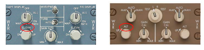
“Multi-Scan Buffering” radars are more sophisticated units with advanced CPU processors and come in two flavors: “Multi-Scan” and “Elevation”. The Elevation Type is the more advanced of the two. Both types utilize multiple scans at multiple tilt angles and save that data into a memory buffer for CPU processing. The primary distinction between the two types stem from how they post-process and display that buffered data, as well as the control inputs available. Below is an example control panel for a Multi-Scan buffering type.

The Multi-Scan Type will have Tilt Controls, which as stated previously, represents a commanded, reference tilt angle. This type of radar combines the multiple scan returns into a singular composite image that is displayed on the WX display. The composite display is essentially a layering of the multiple, angular ‘slices’.
The Elevation Type will not have any Tilt Controls, but will instead have a “Elevation” or “Altitude” control input as shown below.
The Elevation Type has more sophisticated algorithms and post-processing abilities, which allow the pilot to select a reference altitude, for which the CPU will assemble a final composite image that is relevant for the reference altitude as well as some distance above and below it. The following datarefs and commands allow you to configure the various modes available for Multi-Scan Buffering radars. Modes 0 & 1 are typical of the Multi-Scan Type and modes 2, 3 & 4 are typical of the Elevation Type. (Refer to Operating Mode Descriptions Above for each mode).
| Dataref | Type | Description |
|---|---|---|
sim/cockpit2/EFIS/EFIS_weather_multiscan |
int | Weather radar multiscan (ignores manual tilt dataref). |
| 0 = Off, | ||
| 1 = Combine scans (composite), | ||
| 2 = Automatic altitude (on path), | ||
| 3 = All Elevations, | ||
| 4 = Selected Elevation (see datarefs below) | ||
sim/cockpit2/EFIS/EFIS_weather_multiscan_copilot |
int | Weather radar multiscan for copilot display (ignores manual tilt dataref). |
| 0 = Off, | ||
| 1 = Combine scans (composite), | ||
| 2 = Automatic altitude (on path), | ||
| 3 = All Elevations, | ||
| 4 = Selected Elevation (see datarefs below) |
MULTISCAN MODE COMMANDS:
------------------------
sim/instruments/EFIS_wxr_multiscan_auto            Weather radar multiscan auto pilot
sim/instruments/EFIS_wxr_multiscan_on_path         Weather radar multiscan on path pilot
sim/instruments/EFIS_wxr_multiscan_all             Weather radar multiscan all elevations pilot
sim/instruments/EFIS_wxr_multiscan_elev            Weather radar multiscan one elevation pilot
sim/instruments/EFIS_wxr_multiscan_off             Weather radar multiscan off pilot
sim/instruments/EFIS_wxr_multiscan_auto_copilot    Weather radar multiscan auto copilot
sim/instruments/EFIS_wxr_multiscan_on_path_copilot Weather radar multiscan on path copilot
sim/instruments/EFIS_wxr_multiscan_all_copilot     Weather radar multiscan all elevations copilot
sim/instruments/EFIS_wxr_multiscan_elev_copilot    Weather radar multiscan one elevation copilot
sim/instruments/EFIS_wxr_multiscan_off_copilot     Weather radar multiscan off copilot
When in Mode 4 (selected elevation), you can use the following datarefs or commands to configure the selected reference elevation / altitude. Note that using these commands or writing to these datarefs will reset the tilt to 0º and display a flat horizontal slice at the selected altitude.
| Dataref | Type | Description |
|---|---|---|
sim/cockpit2/EFIS/EFIS_weather_alt |
float | In Feet. Weather radar buffer selected altitude pilot's ND – used in computerized weather radar systems instead of tilt. Defaults to -1000 when angular tilt is used. |
sim/cockpit2/EFIS/EFIS_weather_alt_copilot |
float | In Feet. Weather radar buffer selected altitude copilot's ND – used in computerized weather radar systems instead of tilt. Defaults to -1000 when angular tilt is used. |
RADAR ALT SELECTION COMMANDS
-------------------------------
sim/instruments/EFIS_wxr_alt_up                Weather radar alt up pilot
sim/instruments/EFIS_wxr_alt_down              Weather radar alt down pilot
sim/instruments/EFIS_wxr_alt_up_copilot        Weather radar alt up copilot
sim/instruments/EFIS_wxr_alt_down_copilot      Weather radar alt down copilot
Auxiliary Modes – Datarefs and Commands
Radar systems can have auxiliary sub-modes for various purposes to improve the display or detect windshear. The following datarefs and commands can be used to manage the radar sub-modes.
| Dataref | Type | Description |
|---|---|---|
sim/cockpit2/EFIS/EFIS_weather_stab |
int (0 / 1) | Pitch/roll STABilization. |
sim/cockpit2/EFIS/EFIS_weather_stab_copilot |
int (0 / 1) | Pitch/roll STABilization, copilot side. |
sim/cockpit2/EFIS/EFIS_weather_gcs |
int (0 / 1) | Weather radar Ground Clutter Suppression. |
sim/cockpit2/EFIS/EFIS_weather_gcs_copilot |
int (0 / 1) | Ground Clutter suppression, copilot. |
sim/cockpit2/EFIS/EFIS_weather_pws |
int (0 / 1) | Predictive WindShear system. |
sim/cockpit2/EFIS/EFIS_weather_pws_copilot |
int (0 / 1) | Predictive WindShear system, copilot. |
AUXILIARY MODE COMMANDS
-------------------------
sim/instruments/EFIS_wxr_stab_on              Weather radar stabilization on pilot
sim/instruments/EFIS_wxr_stab_off             Weather radar stabilization off pilot
sim/instruments/EFIS_wxr_stab_tog             Weather radar stabilization toggle pilot
sim/instruments/EFIS_wxr_stab_on_copilot      Weather radar stabilization on copilot
sim/instruments/EFIS_wxr_stab_off_copilot     Weather radar stabilization off copilot
sim/instruments/EFIS_wxr_stab_tog_copilot     Weather radar stabilization toggle copilot
sim/instruments/EFIS_wxr_gcs_on               Weather radar ground clutter supression on pilot
sim/instruments/EFIS_wxr_gcs_off              Weather radar ground clutter supression off pilot
sim/instruments/EFIS_wxr_gcs_tog              Weather radar ground clutter supression toggle pilot
sim/instruments/EFIS_wxr_gcs_on_copilot       Weather radar ground clutter supression on copilot
sim/instruments/EFIS_wxr_gcs_off_copilot      Weather radar ground clutter supression off copilot
sim/instruments/EFIS_wxr_gcs_tog_copilot      Weather radar ground clutter supression toggle copilot
sim/instruments/EFIS_wxr_pws_on               Weather radar predictive windshear on pilot
sim/instruments/EFIS_wxr_pws_off              Weather radar predictive windshear off pilot
sim/instruments/EFIS_wxr_pws_tog              Weather radar predictive windshear toggle pilot
sim/instruments/EFIS_wxr_pws_on_copilot       Weather radar predictive windshear on copilot
sim/instruments/EFIS_wxr_pws_off_copilot      Weather radar predictive windshear off copilot
sim/instruments/EFIS_wxr_pws_tog_copilot      Weather radar predictive windshear toggle copilot