Flightplan files must be located in the Output/FMS plans/ directory.
The .fms file is a text file – Unix or Windows line endings are legal and the character set should be UTF-8. Spaces or tabs are allowed as whitespace.
The header of the file must be
I
1100 Version
Since this is a plain text file with no binary data, there’s no difference between ‘I’ or ‘A’ as the first line. The currently supported versions are 3 (legacy, not written but still loaded by X-Plane 11) and 1100 (current).
Next is the AIRAC cycle number of the cycle the file was created with. This line is mandatory as the third line of the file. It is given as a four-digit number:
CYCLE 1710
Next is the departure block, which can be either an airport or any named point in the X-Plane nav database. In case of an airport, the departure block will look like this
ADEP KGSO
optionally, the lines for departure runway, instrument departure and transition can follow:
DEPRWY RW14
SID TRSHA1
SIDTRANS BAWDS
If no departure procedure is part of the flightplan, the SID and SIDTRANS lines can be omitted. If the departure has no transitions, the SIDTRANS line can be omitted. If no departure procedures are available or no loading of a procedure desired, the DEPRWY line can be omitted.
If the flightplan starts at a point other than an airport the departure block looks like this:
DEP CTF
CTF in this case represents a VOR, more precise information on this point is then given in the enroute section of the flightplan.
Next is the destination block. It is similarly structured to the departure block and can include destination airport, runway, arrival, arrival transition, approach and approach transition:
ADES KRDU
DESRWY RW05L
STAR ALDAN1
STARTRANS ROA
APP I05L
If any off APP or STAR is set, the DESRWY is required! STAR and STARTRANS can be omitted if no arrival is desired. APP and APPTRANS can be omitted if no instrument approach is desired. APPTRANS is optional and can follow APP, just like STARTRANS is optional after the STAR. APPTRANS can be omitted if no transitions are available for the given approach or vector to final is desired.
An exception to the above rule is a circling approach with no runway, in which no DESRWY will be set. In this case, the loading of STARs prior to this approach is limited to STARs with non-empty trunk routes, as with no runway, no runway transition can be loaded.
The name of the approach must be given in the format of ARINC 424.18+, section 5.10. Examples: I26L, B08R, R29, V01L, N35, R35-Y, VDM, NDBB, LOCD, …
If the flightplan ends at a point other than an airport the destination block looks like this:
DES RDU
RDU in this case represents a VOR, more precise information on this point is then given in the enroute section of the flightplan.
Next is the enroute block of the flightplan. It starts with the number of enroute waypoints:
NUMENR 9
This is the number of waypoints in the flightplan that are NOT part of an instrument departure, arrival, transition, approach or missed approach. The waypoints listed can be either direct (DRCT) legs or via an ATS airway. The format is similar to the v3 flightplan, but adds a field for the via airway or other special rule of the waypoint.
Only track-to-fix legs are listed here. Note that any special leg types can be loaded as part of a published procedure, via the departure or destination block explained above.
A typical enroute block after the NUMENR field might look like this:
1 KCUB ADEP 4.000000 33.970470 -80.995247
3 CTF DRCT 0.000000 34.650497 -80.274918
11 NOMOE V155 0.000000 34.880920 -79.996437
11 LILLS V155 0.000000 34.935440 -79.930206
3 SDZ V155 0.000000 35.215481 -79.587936
11 OCHOC V155 0.000000 35.402336 -79.361153
11 MOATS V155 0.000000 35.621601 -79.092964
3 RDU V155 0.000000 35.872520 -78.783340
1 KRDU ADES 435.000000 35.877640 -78.787476
The first column is the type of waypoint, and corresponds to the first column in a v3 .fms file. It is 1 for airport, 2 for NDB, 3 for VOR, 11 for named fix and 28 for unnamed lat/lon waypoints.
The second column is the identifier of the waypoint, and corresponds to the second column in a v3 .fms file.
The third column is the via/special column. It can have the following values: ADEP/ADES for departure or destination airport of the flightplan, DRCT for a direct or random route leg to the waypoint, or the name of an airway or ATS route to the waypoint.
The fourth column is the required altitude in feet and corresponds to the third column in a v3 .fms file.
The fifth and six columns are the latitude and longitude of the waypoint, given in decimal degrees and correspond to the fourth and fifth column of a v3 .fms file.
Example
This is an example of a valid v11 flightplan .fms file:
I
1100 Version
CYCLE 1710
ADEP KCUB
DEPRWY RW13
ADES KRDU
DESRWY RW05L
APP I05L
NUMENR 9
1 KCUB ADEP 0.000000 33.970470 -80.995247
3 CTF DRCT 0.000000 34.650497 -80.274918
11 NOMOE V155 0.000000 34.880920 -79.996437
11 LILLS V155 0.000000 34.935440 -79.930206
3 SDZ V155 0.000000 35.215481 -79.587936
11 OCHOC V155 0.000000 35.402336 -79.361153
11 MOATS V155 0.000000 35.621601 -79.092964
3 RDU V155 0.000000 35.872520 -78.783340
1 KRDU ADES 435.000000 35.877640 -78.787476
Backward compatibility
X-Plane 11.10 can still load the following other, older formats of flightplans:
- v3 .fms files, containing waypoints only but no airways or procedures, can be loaded into the GPS or FMS
- .flp files, containing waypoints and airways, can be loaded by the airliner FMS
- .fml files generated with the v11 FMS can be loaded by the airliner FMS
X-Plane 12 can read and write v11 .fms files.
In X-Plane 11, we added two new features aimed at making joystick configuration easy for users:
- “image maps” that show you a picture of your joystick, with each of its buttons/axes labeled, and
- detailed default configurations for joysticks.
Both are described in the .joy file corresponding to your joystick. These files are located in Resources/joystick configs/.
Creating a default joystick configuration file
The easiest way to create the default joystick configuration: plug in your joystick, configure it as you’d like, then hit the “Save as Default for [device]” button there on the joystick configuration screen.
That will output a .joy file wherever you’d like (recommended that you stick it in Resources/joystick configs/). You can confirm it worked by hitting the “Reset to Defaults for [device]” button and confirming that none of your axis or button assignments changes.
At this point, if you were to delete your preferences, when you plug in your joystick, you would see that your previous configuration gets loaded—your joystick would be instantly ready to use!
Creating an image map
Our image maps consist of two things:
- a PNG image, which we’ve gotten clearance from a joystick manufacturer to distribute with the sim, and
- information in the .joy file noting the pixel coordinates of that PNG image where buttons, axes, & hat switches should be labeled.
So, suppose we have an image that is 1,000 px on each side. If the very center of that image corresponds to a particular button, we’d put a line in the .joy file to the effect of “Button x should be labeled at position (500, 500).” (We’ll get to the actual syntax below.)
Unlike the default joystick configuration, we can’t auto-generate the image map. So, you’ll need to use an image editor to figure out where in the image each label for your buttons, axes, and hat switches should go. So, you’ll specify the coordinates for these things in pixels, with (0, 0) in the upper left of the image.
The easiest way I’ve found for getting these coordinates (if you don’t want to spend a zillion years in Photoshop hovering over portions of the images and noting the pixel coordinates in the Info tool) is to use an online image map generator. Here’s how that works:
Upload the image you want to work with.
- Click the square or circle button.
- Click within the image wherever you want to add an annotation. A new line will appear in the source at the bottom of the window, giving you the coordinates of that shape. We need only the first two (x, y) coordinates.
- Continue clicking Add Area and noting the new coordinates until you’ve gotten everything you need.
See the “View” section of the following file format description for the syntax of the image map text.
Notes on the image files
X-Plane only supports .png images with an optional transparent background. While there are no official size limits, we recommend the image be no larger than 2000×2000 pixels to avoid impacting sim performance. X-Plane will also scale large images automatically while maintaining the image map coordinates you specify.
Nitty gritty: a sample .joy file, as of X-Plane 11.20
See examples of finished .joy files in X-Plane 11/Resources/joystick configs.
I
1100 version
JOY
# ^ The header; must be the first thing in the file, verbatim.

# Operating system(s) this file applies to.
# Windows, macOS, and Linux will index the axes differently, so a file
# that correctly configures your joystick on one platform is *not*
# guaranteed to work on the other.
OS: Windows
# Other valid options:
# OS: Mac
# OS: Linux
# Zero or more device names (provided by the operating system, as seen in the UI) that this .joy file describes.
# (Note that you need at least one name or one ID, described below.)
# If more than one device is named, we're saying that *any* of those devices should be configured
# using the *same* defaults and the same image maps.
Name: [device name]

# Zero or more USB identifiers (vendor ID + product ID) that this .joy file describes.
# (Note that you need at least one ID or Name, described above.)
# If more than USB identifier is given, we'll use this .joy file to configure *any* of those devices.
# You can specify the IDs in either hex or decimal form.
# For instance, the following are equivalent:
#    ID: VID:0x046DPID:0xC214
#    ID: VID:1133PID:49684
# ...since hex 046D == 1133, and hex c214 == 49684.
ID: VID:[vendor ID]PID:[product ID]

# Optional: Specify the name X-Plane should display for the device in the user interface
# (if this is different from the name the operating system provides)
Display: [device name override]

# Zero or more view sections
# These will be presented in the UI, and you can select different views for the same device
# (e.g., you might have one looking at the front of the device, one looking at the back,
# and a third looking at the throttle quadrant). Presumably you will annotate *different*
# controls for each view.
View: [view name]
-----------------------------------------------------------------------
Image: [image_name.png]

# Then, within the view section, you can zero or more of the following:
#   - buttons
#   - hat switches
#   - axes
#   - axis groups

# Buttons are easy; just specify which button you're talking about, and where in the image you
# want the "dot" for that button positioned.
# Note that these (x, y) pixel coordinates---like all the coordinates that follow---use the top left as (0, 0).
Button [button index]: [x coordinate in the image] [y coordinate in the image]

# Buttons can also take an optional *label* to display in the UI, like this:
Button [button index] ([label for UI]): [x coordinate in the image] [y coordinate in the image]

# Axes, like buttons and hat switches, can take an optional label.
Axis [axis index]: [x coordinate] [y coordinate]
Axis [axis index] ([axis label]): [x coordinate] [y coordinate]

# In addition, axes can take an optional *axis direction*. This must be one of x, y, or z (lowercase).
# If you provide a direction, we'll use that letter when labeling the axis in the UI.
# So, the following are also valid axis labels:
Axis [axis index] ([x/y/z]): [x coordinate] [y coordinate]
Axis [axis index] ([axis label]; [x/y/z]): [x coordinate] [y coordinate]

# Finally, you can optionally group axes together in the UI.
# For instance, you probably don't want to display the x and y axes on your joystick separately.
Axis Group ([label for this group, displayed in the UI]): [1st axis index in this group] [2nd axis index]
Axis [index] ([x/y/z]): [x coordinate in the image] [y coordinate in the image]
Axis [index] ([x/y/z]): [x coordinate in the image] [y coordinate in the image]

# Zero or one assignment section
# This describes the default configuration for the device.
################################################################
# NOTE:
# You almost certainly don't need to know the syntax for the
# assignments section, because you should be auto-generating
# it from an actual configuration (by hitting the
# "Save as Default for [Device]" button in Settings > Joystick).
################################################################
Assignments:
------------------------------------------------------------------------

# Any number of axes, buttons, and hat switches.

Axis [axis index]: hidden
Axis [axis index]: [joy use]
Axis [axis index]: [joy use] reverse
Axis [axis index] Type: linear or centerable
Axis [axis index] Calibration: auto
#	Valid joy uses are:
#	 joy_use_none	joy_use_ptch	joy_use_roll
#	 joy_use_hdng	joy_use_thro	joy_use_coll
#	 joy_use_lbrk	joy_use_rbrk	joy_use_prop
#	 joy_use_mixt	joy_use_heat	joy_use_flap
#	 joy_use_vect	joy_use_swee	joy_use_sbrk
#	 joy_use_disp	joy_use_reverse	joy_use_elev_tr
#	 joy_use_ailn_tr	joy_use_rudd_tr	joy_use_thro1
#	 joy_use_thro2	joy_use_thro3	joy_use_thro4
#	 joy_use_prop1	joy_use_prop2	joy_use_prop3
#	 joy_use_prop4	joy_use_mixt1	joy_use_mixt2
#	 joy_use_mixt3	joy_use_mixt4	joy_use_reverse1
#	 joy_use_reverse2	joy_use_reverse3	joy_use_reverse4
#	 joy_use_gear	joy_use_tiller	joy_use_back_thro	joy_use_view_lr
#	 joy_use_view_ud	joy_use_view_zoom	joy_use_camera_lr
#	 joy_use_camera_ud	joy_use_camera_zoom	joy_use_gun_lr
#	 joy_use_gun_ud

Button [button number]: hidden
Button [button number]: [command path, like "sim/operation/quit"]
Hat Switch [hat switch number]: hidden
Hat Switch [hat switch number] Direction [hat switch direction]: [command path, like "sim/operation/quit"]
#	See X-Plane/Resources/plugins/Commands.txt for a complete list of commands
Coping with hardware eccentricities
“Phantom” buttons & axes
Sometimes, your USB hardware will report controls that don’t actually correspond to any physical axis, button, or hat switch. In that case, you can mark the control as “hidden” in the Assignments section (see examples above). Doing so will cause X-Plane to ignore that “phantom” control entirely, and not show it anywhere in the app.
(Normally, if you specify image mappings, but leave some axes, buttons, or hat switches out of all image mappings, X-Plane will add one final “view” called Other Controls to display them. Marking nonexistent controls as “hidden” can prevent this.)
Axes with limited range of motion
If your USB hardware reports a wider range of axis motion than the device is actually capable of sending, you may want to specify “relaxed” calibration in the header section. For instance, if you’re a custom cockpit builder, and your axis reports 16 bits of travel, but you only use 10 bits–during calibration, X-Plane may never recognize the range of motion as complete, although you know it is.
Calibration: Relaxed
This is not recommended if you have off-the-shelf hardware from a consumer hardware company like Saitek, Logitech, Thrustmaster, CH Products, etc.
Devices with more than one hat switch
Some devices come with multiple hat switch buttons. By default, X-Plane only recognizes one as a hat switch and the rest are considered separate buttons. You can group a set of 4 buttons into a virtual “hat switch,” which can make the button image mapping cleaner and easier to understand.
Specify the buttons to be grouped in up/right/down/left order, then associate your desired x/y image coordinates with the “up” button.
Hat Switch Group ([label for UI]): ["up" button index] ["right" button index] ["down" button index] ["left" button index] Button ["up" button index]: [x coordinate in the image] [y coordinate in the image]
Hat switches also take an optional label, so you can use either of the following:
Hat Switch [hat switch index]: [x coordinate in the image] [y coordinate in the image]
Hat Switch [hat switch index] ([label in the UI]): [x coordinate in the image] [y coordinate in the image]
Toggle switches: when a “button” isn’t a button
X-Plane 11.10 and greater support special configuration for joystick controls that send plain button presses to the sim, but which are conceptually not buttons.
Consider the Thrustmaster HOTAS Warthog:
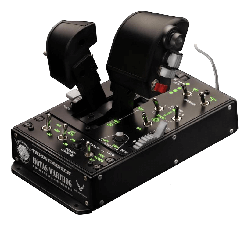
It has a number of silver switches, which fall into three different categories:
- Normal 2-position switches. When the switch is in one of these two positions, it sends a perpetually “held” button press, and while it’s in the other position, it sends no button press at all. The EAC on/off switch on the Warthog is an example of this.
- Normal 3-position switches, which send no button press in the center position, but send a perpetual “hold” for two different buttons in the up and down states. The autopilot switch on the Warthog is an example.
- Special 3-position switches which send a normal (momentary) button press in one direction (you have to keep holding the switch for it to continue sending the button press), no button press in the center, and a continuous button press when they “lock” into the third state. The engine toggles on the Warthog are like this: “ignition” is momentary, “normal” is center, and “motor” is the toggle-and-hold.
X-Plane 11.10 provides two .joy annotations to handle all three of the above cases: “momentary” and “virtual” buttons. When a button is marked as momentary, X-Plane will only run the associated command on the initial down-press, rather than running the command continuously for as long as the button is “down.” Likewise, “virtual” buttons are triggered when a “real” button (i.e., a button that you see in the UI when you have no .joy configuration file) is pressed or released—you pick which.
Here’s how it works in the above 3 cases:
The 2-position switch
This requires an immediate press-and-release when the “button” goes “down,” rather than firing the associated command continuously as long as the switch is in that state. Likewise, it requires a press-and-release when the “button” is “released (i.e., when the switch transitions to the “off” state).
The solution: mark the “button” as momentary, and create a new virtual button that fires on the release of the “button.” Example:
Button 15: Momentary
Virtual Button 100: Release Button 15
Note that this creates a new button at index 100—make sure you don’t actually have 100 physical buttons, or your newly created virtual button won’t work. In the rest of the file, you can refer to “Button 100” as though it were perfectly normal—you can map it to a view, assign a default command to it, etc.
The 3-position switch
This requires a single press-and-release when the two “buttons” are “pressed” initially, and it requires a separate command (for the center state) when either “button” is released.
The solution: mark the two “buttons” as momentary, and create a new virtual button that fires when either button is released. Example:
Button 12: Momentary
Button 13: Momentary
Virtual Button 105: Release Button 12, Release Button 13
The “special” 3-position switch
In this case, one of the button presses can actually be left alone—since it already behaves like a normal, momentary button, it doesn’t require any special configuration in the .joy file.
To cope with the “locked” button press, we need to once again mark it as momentary, and for the third state (which sends no button press at all), we need to create a virtual button that fires when either “button” is released. Example:
Button 18: Momentary
Virtual Button 105: Release Button 18, Release Button 31
Grouping switch “buttons”
In the case of our example Warthog above, all the states for one switch exist in the same space on the joystick. This can be problematic when you try to map two, three or even more of these switch states to very similar coordinates on your device image. The solution to this is a “Button Group:”
Button Group ([display name]): [button #] [button #]
Button # ([display name]): [x coordinate in the image] [y coordinate in the image]
Button # ([display name]): [x coordinate in the image] [y coordinate in the image]
You can specify the buttons to group together in any order. The first coordinates listed are used to position the image labels, but we recommend giving the same coordinates to all buttons in the group just for the sake of clarity.
Example:
Button Group (3-way Switch): 104 102 103
Button 102 (↑): 100 200
Button 104 (Center): 100 200
Button 103 (↓): 100 200
New capabilities in X-Plane 11.20
Group buttons and axes together
“Configuration Groups” allow you to group axes and buttons together. Note that X-Plane does not differentiate between configuration group types, so each must have a unique number. Example:
Configuration Group 2 ([display name]): Axis 2 3 Button 12
“Exclusive Configuration Group” is designed for hardware like the PS3 controller, where every button is also an axis. You specify the axis and the button, and the user has to choose in the UI which to use (and X-Plane will ignore the other). Example:
Exclusive Configuration Group 3 ([display name]): Axis 10 Button 4
New ways to use axes
Self-centering axes operating as linear axes
If you assign a self-centering axis to a linear axis assignment, we use the deltas from centered to move the throttle in that direction; a big movement from centered gives you a big jump in the axis position, etc.
For example, if you assign the Y of your X/Y stick to throttle, instead of the centered position always sticking your throttle at 50%, it instead leaves the throttle alone. You push the axis forward a bit, the throttle goes up (and remains there when you bring the axis back to center). Pull the axis back a bit and the throttle will go down. It requires some hint to us in the .joy file about the type of axis. A device with no .joy file at all will not work. To see it in action, you’ll need a .joy file with one of the following:
- an explicit axis type line in the assignments section
- a default assignment that would require a centered axis (pitch/roll/yaw/etc.)
Example:
Axis [axis index]: joy_use_roll
Axis [axis index] Type: centerable
Changing a device with no .joy file from pitch to something else can’t do it, because you may have accidentally set a linear slider to pitch at some point.
Axes operating as commands
In the .joy file, specify the axis type as either linear or centerable. Then, in the X-Plane axis usage dropdown choose “Custom commands” and you can assign some number of commands (based on the type of axis) to be fired as you move the stick:
- Linear axes always have 2 configurable slots, self-centering axes always have 4.
- You can assign up to that number of different commands to each slot.
- The assignments in each slot get triggered when you move the axis into a certain range of the stick. (E.g., slot 1 on a linear axis is from about 0 to 50%, slot 2 is from 50 to 100%.)
Axes operating as hat switches
When you have a 2-axis group specified in the .joy file as described above, you’ll get a toggle in the UI next to the group’s name to choose “axis” or “hat switch” mode.
Handling VR controllers
“Reserved Configuration Groups” are specified the same way as the configuration groups as above, but the default config is all-or-nothing. This was designed for VR, where we want the stick+clicker to either all be for menu manipulation, or to totally disallow a partial menu manipulation config (i.e., you can’t set the X/Y to pitch & roll, but keep the clicker to be “menu enter”). Example:
Reserved Configuration Group 1 ([display name]): Axis 0 1 Button 3
Automatic calibration can be specified to bypass all calibration in X-Plane. All axes on the device must be specified as such. Example:
Axis 2 Calibration: auto
X-Plane also checks for and complains at you if you don’t have the required VR assignments (VR X/Y axes plus VR menu enter command) mapped to any VR controller.
New capabilities in X-Plane 12.00
Mark an axis as control-loaded for trim
If an axis is control-loaded instead of spring-entering, its “center” is decided by the control loading software rather than a fixed position. To keep X-Plane from adding trim onto the already trimmed position of the axis, mark an axis that centers itself by force feed back with the tag “ffb”, like so:
Axis [axis index]: [joy use] ffb
This article describes the existing command-line options supported by X-Plane; it is essentially an extract of X-Plane’s command line help. You can find instructions on using command line options here.
Command Line Options exist to control program behavior beyond the default settings.
X-Plane can take a number of command-line flags, in the form of –flag or–flag=value. While OpenGL options are available for all X-Plane-related applications; the frame-rate test is only for X-Plane itself.
–help or -h Prints the message listing all command-line options, then quits.
Sound related Options
–no_sound Runs without initializing sound – can help identify a problem with sound hardware.
Options to Disable Video Hardware Acceleration
Normally X-Plane uses all available hardware capabilities to maximize the frame rate, these options force X-Plane not to use some aspects of hardware acceleration. This impacts frame rate, but can sometimes allow you to work around driver bugs.
–no_vbos Disable the use of vertex buffer objects, as defined by GL_ARB_vertex_buffer_object. VBOs are used to accelerate all aspects of X-Plane drawing.
–no_fbos Disable the use of framebuffer obects, even if the hardware supports them.
–no_pbos Disable the use of pixelbuffer obects, even if the hardware supports them.
–no_sprites Disables the use of point sprites, as defined by GL_ARB_point_sprite. Point sprites are used to accelerate runway lights, among other things.
–no_pixel_counters Disable pixel counters, as defined by GL_ARB_occlusion_query. Pixel counters are used to calculate sun glare, among other things.
–no_aniso_filtering Disable anisotropic filtering of textures, as defined by GL_EXT_texture_filter_anisotropic. Anisotropic filtering is used to make runways look better.
–no_hw_mipmap Disable hardware accelerated mipmap-creation, as defined by GL_SGIS_generate_mipmap. X-Plane will still use mipmapping, but it will create the mipmap images on the CPU instead of the GPU.
–no_fshaders Disable the use of fragment shaders, even on hardware that reports having them.
–no_vshaders Disable the use of vertex shaders, even on hardware that reports having them.
–no_glsl Disable the use of GLSL, even on hardware theat supports it.
–no_threaded_ogl Disable the use of OpenGL via multiple threads.
Options To Enable Incompatible Video Hardware Acceleration
X-Plane will in a few cases intentionally disable hardware acceleration to work around known driver compatibility bugs. You can force X-Plane to use the feature anyway (if the card supports it) with these options, but they may cause the sim to crash.
–use_vbos Forces the use of VBOs, even on drivers where we at one point found them to be unstable.
–use_sprites Forces the use of point sprites, even on drivers where they cause bugs.
–use_fshaders Force the use of fragment shaders, even if they would not normally be used.
–use_vshaders Force the use of vertex shaders, even if they would not be used.
–use_glsl Force the use of GLSL even on cards where we would avoid it due to driver compatibility problems.
–force_run X-Plane will not run on a machine that does not appear to have some minimum requirements, like at least two texture units. This will allow X-Plane to run no matter what the hardware looks like. Please note that most of the time if X-Plane out-right refuses to run, it will probably crash later if –force_run is used.
Frame Rate Options Logging
–fps_test=n This runs X-Plane in frame-rate test mode. The number indicates a frame rate test number, which is 3 digits indicating a combination of camera angle, scenery complexity, and weather settings. X-Plane will run for 90 seconds and quit, outputting 3 framerates to the Log.txt file for panel view, no-panel view, and paused no-panel view. This can be used to get repeatable performance measurements without changing preferences. (The preferences file is ignored when the framerate test is in effect.)
–require_fps=n When used after –fps_test this puts X-Plane into a pass-fail mode. The sim will run only one 30 second test with the flight model paused. The sim will then exit with 0 if the measured fps is higher than N or 1 if the fps is lower. This can be used to create a shell script that will automatically detect whether X-Plane performance is as expected.