(This blog entry explains the background of split beziers – the next parts will explain the bugs that they cause and the workarounds.)
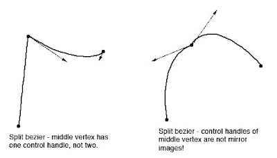
In apt.dat terminology, a split vertex is any vertex of a polygon where the control handles on either side of the vertex are not exact mirror images. (When there is only one control handle it is therefore by definition split!)
You need a split bezier any time you want to:
- Have a sharp corner between two curves and control the tangents of the curves or
- Have a sharp corner between a truly straight segment and control the curve of the next segment.
Now here’s the rub: the apt.dat format does not allow for split beziers – each curved point has only one control handle – the other is calculated by x-plane by mirroring…thus no vertex can ever be split.
(This is due to a total lack of brains on my part when working on the apt.dat format, which is quite embarrassing considering how long I spent thinking about it.)
The Hack
There is a way to simulate a split bezier: if you use zero-length segments (that is, multiple points on top of each other), you can create a shape that works as if it is split.
In its simplest, a split bezier can be created by using 3 vertices.
- The first vertex uses the control handle of one side.
- The second vertex is not curved.
- The third vertex uses the control handle of the other side.
Why does this work? Well, a bezier curve between a curved point and a straight point has zero length if the two points are on top of each other. So what we’ve done is inserted two zero-length segments. The result of this mess is that the control handles on either “side” of this cluster of points can be different!
Is the second point really necessary! Yes! The reason is this: if we simply had the first and third point (two bezier points with different control handles), X-Plane would draw a loop from the first to the second. Remember: two colocated points with ONE control handle form a zero-length curve, but two colocated points with TWO control handles form a loop.
(To see this for yourself, just draw some examples in WED or photoshop. 🙂
Line Continuity
There is one more wrinkle we have to add to the puzzle in order to understand how this works, and what the pitfalls are: line continuity.
A bezier path (taxiway edge, linear segments, etc.) is made up of one or more bezier curves. Each curve has zero or more attributes.
When X-Plane draws the actual taxi lines and lights, it looks for continuous adjacent bezier curves with the same attribute and makes sure the linkage between those attributes is correct.
(This linkage is computed separately for each type of property. So if you have taxiway lines on two segments and lights on one, the taxiway lines will still link!)
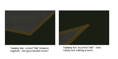
The picture above shows a correct vs. an incorrect link. When dealing with unsplit beziers and non-curved points, linkage is pretty much automatic, it just works.
But there is a pitfall to our above hack for split vertices: we have three points on top of each other. They must all have the same attributes in order for linkage to work. A “break” in the continuity of the line for one of the zero-length segments still counts as a break in linkage. The picture on the right was produced by creating a split bezier and removing the double-yellow-line attribute from the second of three vertices.
In my next post I’ll explain the bugs that this causes in X-Plane 8.60.
