I sometimes get questions from authors considering how much to rely on a 2-d panel mapped to 3-d via the panel texture vs. a true 3-d panel. I can’t comment on what will look best, but I can comment on the relative performance characteristics of both techniques, and the answer might surprise you: in some cases you’ll get better performance by modeling directly in 3-d.
The 2-D Way
When you use the panel texture to make an object, X-Plane goes through a lot of steps to create the final result:
- Your panel has to be rendered in 2-d. We atlas your panel textures, but we don’t necessarily order them optimally – we don’t know the optimal order. Each generic instrument is at least one batch, perhaps even two. Those batches have very low vertex count, and the vertices are stored non-optimally on the CPU. There may be a fair number of texture changes between instruments.
- If you use ATTR_cockpit_region, we then go back and do the same thing…again! Why? Well, we need your panel’s raw color (“albedo” to graphics nerds) and the emissive light given off by anything self-lit separately, so that we can do correct 3-d lighting.
- Both of these are rendered to an off-screen texture that the video driver will feeel obligated to preserve at all costs, putting pressure on VRAM.
- Only when all that is done do we begin drawing your object, with the usual batches to change to panel texture and change back, perform animations, etc.
If this seems expensive, that’s because it is. Periodically users send me airplanes to look at their performance, and lately I’ve been seeing a lot more problems with 2-d panels (that fuel 3-d cockpits) being the performance bottleneck, not the 3-d modeling itself.
The 3-d Way
What if we want to go 3-d? Well, we’re going to “eat” a lot more of what your 3-d pit already has:
- You’ll need a lot more animations to move all of those parts.
- You’ll need new batches with ATTR_lit_level to dial up and down various lighting levels.
But you do get some advantages:
- Geometry in objects is processed about as optimally as we possibly can. All of that work we’ve done on the rendering engine to make OBJs fast is available in your cockpit. So you can increase 3-d detail ‘for free’.
- Your lit geometry can be drawn in a single pass (we don’t need to prepare two separate lit textures). So for example a needle would take three batches via the panel-texture route (a batch to rotate the needle for albedo, a second batch to draw the rotated night needle, and a third batch to draw the resulting texture in 3-d) but only one if you use the OBJ directly.
- Since you organize your textures for OBJs, you can guarantee that all of the cockpit stuff is together, saving texture thrash.
- You can use normal maps to add per pixel detail to your cockpit; panel textured geometry cannot be normal mapped.
A Balancing Act
Given the high cost of panel texture relative to native OBJ drawing, you’d think going native OBJ would be a no-brainer, right? Well, not quite.
A needle is an easy case: you can model a needle using a rotation animation, so your implementation in an OBJ and our generic instrument are quite similar. Same with the throttle lever generic instrument.
But what about a “glass pie indicator”? What about a moving map? What about a rotary?
There are some generic instruments that have “movement” for which there is no equivalent OBJ technique. With these generics, the generic instrument/panel code may be able to render the generic quite a bit more directly than your OBJ can simulate the same effect.
This is my suggestion on a cut-off: if you can directly model a generic instrument with an OBJ (needles, throttles, and other “simple moving things”), consider 3-d. If you would have to use a lot of extra texture space, copies of your mesh, or a lot of show-hides, use the panel texture.
Your goal should not be to eliminate the use of panel texture. But if you can cut panel texture down to a single 1024 x 1024 region from a larger area, you’ll probably see a performance win or a reduction in your airplane’s system requirements.
Performance Test First
Final thought: before you invest months in a complex cockpit design, mock up the “work-load” X-Plane must do and performance test it! For an OBJ, simply make one moving instrument and duplicate the mesh to get the number of expected animations. For the panel, drag out a bunch of instruments, make custom textures and just paint junk into them with photoshop. The goal is to make X-Plane do the same amount of work as it will in the final version. Then fly your test panel on target computers and observe performance.
The short answer is: to save memory.
The cars and replay seem to be a case of damned-if-we-do, damned-if-we-don’t. If we don’t stop the cars and reverse them in replay, we get piles of bug reports. If we do try to replay the traffic, we get bug reports too.
The current implementation is a bit strange: when you replay traffic, the cars will go back a bit in time, but at some point they will just stop and refuse to reverse any more. What’s going on?
The answer is that the cars have the memory of a goldfish. They simply don’t remember where they came from. Each car knows what “link” it is on, and about when it got onto that link and how fast it is going. (A link is a single straight piece of road.) So when we go into replay, we can easily move the cars along their links as time goes forward and backward.
But when we reach a time earlier than when the car entered the current link, the car has know idea how it got there, so it is forced to stop.
This is a simple case of not wanting to burn four tons of memory on a feature that is mainly visual. To replay the cars, we would have to accumulate a history of every link a car has been on as it drives. For 20,000 cars and a sim that’s been running a while, that’s a lot of memory to burn just in case you happen to hit the replay button.
In fact it gets worse. The cars are kept in a data structure that tells us who needs to make a driving decision and when.* This structure is optimized for the cars moving forward in time. We’d have to make and maintain an entire second copy of this structure to move the cars backward; again burning CPU and memory while you fly just in case you might hit a replay.
So instead we just provide replay on the current link.
* Programming nerds: the cars are in a priority queue by time to next navigation decision. I consider this to be very clever.
Previously I blogged about the difference between integrated first person shooters (FPS) and flight simulators, and how these differences mean that FPS tend to adopt new graphics technology significantly ahead of flight simulators. One of the major differences is that a FPS often will have its content packaged with the rendering engine in a single, unified product, while a general purpose flight simulator is expected to cope with third party content.
The need to be a platform for external content doesn’t just impact our ability to optimize for “special cases” (e.g. we can’t assume anything about third party); it also puts more pressure on the rendering engine to be robust in the case of error.
X-Plane has low level and high level scenery abstractions.
- Low level: an OBJ is low level. You give us a textured mesh, and we draw it. We don’t process the mesh, we don’t interpret it, we just draw what you made in Blender, AC3D, etc.
- High level: a forest. You tell us the outline of the forest’s area and give us some trees and we fill in the forest, picking trees and placing them.
Now there is always the risk that third party content can look stupid. If you model an airplane and you use 4 quads for each engine, your airplane is going to look bad, and there’s nothing the rendering engine can do to fix that.
But with higher level abstractions, the problem is more subtle. If the input data to a high level abstraction has a problem, X-Plane’s rendering might look bad. But what constitutes a problem?
In the case of forests, if the polygonal area of a forest is too thin (along certain axes) we will fail to put any trees into the polygon. Exactly what represents too thin isn’t particularly well documented or even easy to measure. This is difficult for third parties, because they don’t have an explicit set of guidelines for “you will make the rendering engine grumpy if you do X.”
This is the kind of thing that, in an integrated FPS, is much easier to cope with. The art team tries a technique, and if it looks bad, they email the rendering engine coder. The coders then either fix the rendering engine or tell the artist “don’t do that”.
In our case, we need to be more robust in the case of input data problems because we can’t tell everyone who tries X-Plane “don’t do that”, particularly when the edge cases may change with rendering engine improvements. So whereas a rendering engine feature in an integrated FPS might be useful if it looks good when used in a few usage cases , a rendering engine feature in X-Plane is only useful when it looks good under most usage cases.
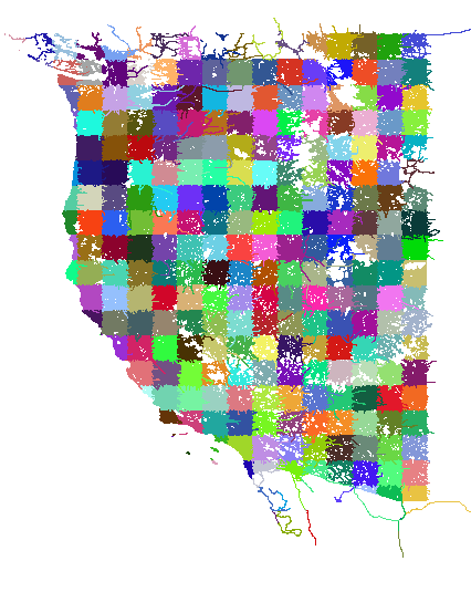
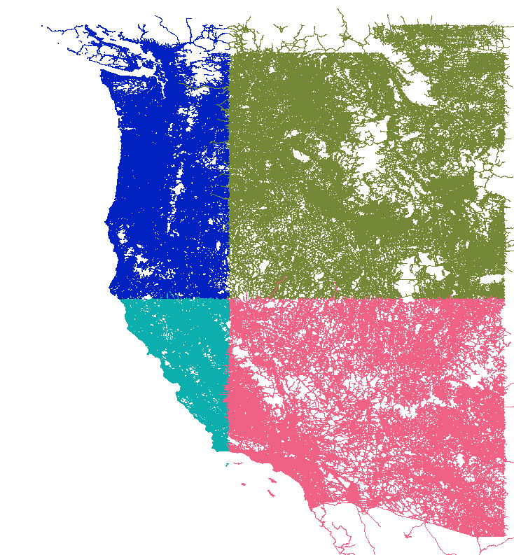
This is two pictures of “tilings” of OpenStreetMap for use in global scenery. I downloaded a OSM new planet extract about a month ago; in the 11 months since I last grabbed it, the data size has grown 56%! The new, larger file required some changes to my extracting code. After much debugging, I was able to see this in QGIS:
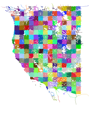
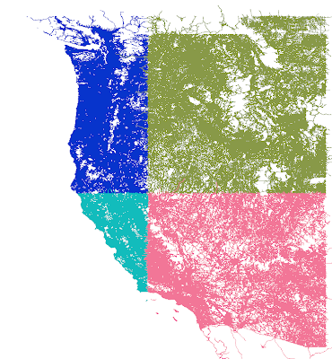
The first picture is 1×1 tiles, which are derived from the second picture (10x10s). You’ll see some “ragged” edges. This is because the cutting scheme leaves whole roads of interest in one piece even outside the tiling bounds. Later, more sophisticated code crops the road when the actual DSF is built.
The OSM processing tools are part of the open source scenery tools; I will get my changes checked in to source control over the next few days, although my code is only one of dozens of programs for bulk processing OSM.
I’ve been working on road processing today; one of the tricky problems with OSM data is that, because an OSM map is often a collection of vectors from separate authors, the results can be a huge number of very small segments, as nearby road features from different data sources cross each other. (Basically you get “thrash” between the two vectors from different sources and our tools solve this by adding a huge number of extra vertices.)
I am trying to run this data through an algorithm called Iterative Snap Rounding (ISR) to reduce this mess of vertices, and for the purpose of this blog article there’s one thing you need to know about ISR: it is really, really slow. So for the next few minutes, I figured I’d start poking at some of the issues that came up at the X-Plane Congress in France this summer.
One question that came up was whether/when X-Plane will go 64 bit. Here’s my current thinking:
We can’t drop 32-bit X-Plane. Too many users have a 32 bit operating system, or a 32-bit CPU. One thing I have been resisting for X-Plane 10 is a ratcheting up of the system requirements to only top-end game machines. While 64 bit is becoming more prevalent and has the potential to be a big win for users who load the sim up with third party add-ons and have a high-end graphics card, plenty of people buy a computer first and then discover X-Plane. Those users will often have a system that is low end (by X-Plane standards).
If we start cranking the system requirements (you have to have 64-bit, you have to have a DX10 class graphics card, you have to have 2 GB of RAM) then more users who might discover X-Plane won’t even be able to run the demo, and that will be bad for X-Plane’s growth.
So the question is not “when will we switch from 32-to-64 bit” – it is “when will we support both 32 and 64 bit.”
I think we will get there during the version 10 run, but I don’t think it’s that likely that we’ll ship 64 bit right out of the box. 64 bit is more of a performance enhancement* than a new feature. The features we have strong motivation to get into 10.0 are:
- Anything that raises the system requirements, because we don’t want to raise system requirements after we ship in a free update.
- Anything that enhances the authoring SDK, where it might be useful for authors to know that every version of X-Plane 10 has a feature.
- Of course, we want to ship any feature that looks really good and gets people excited.
- Foundation features that support other featuers have to go in first. So some enhancements that will ship in 10.0 are there because without them other tech couldn’t be rolled out.
64 bit is important, but it is a feature that only helps some of the user base, and helps by making the sim more expandable; the sim is still usable without it. So we’ll get there, but new features are a zero sum game so I think 64 bit is more likely to be a free patch than in-the-box.
(At this point I expect the various 64-bit OS users who have been asking for a 64-bit app for years to flame the heck out of me and point out that I am a cranky old bastard who doesn’t realize that 64 bit is now everywhere and totally pervasive and that this is therefore the most important thing we could possibly do. Before you dig in, hang on one second, let me put on my asbestos flame-retardant jacket. Okay…fire away. 🙂
Oops…ISR just finished…with a seg fault. Gotta go!
* As a performance enhancement, 64 bit is a weird one; because a 64-bit app uses more memory for pointer-based structures, the same data structures become larger, thrashing on-chip caches more. The real benefit to 64 bits is to allow X-Plane to use more than 3 GB of physical RAM.
To put it mildly, I am buried. If you have emailed me in the last few weeks, I apologize, but basically whatever is going on, I can’t look at it for at least a few more weeks. The four posts for June is an indication of work-load. In particular, since a lot of what I am working on is v10, it is under the radar until we do some kind of more formal announcements.
I did find a little bit of time last night to fix a MeshTool bug (thanks to the users who found this – it was a tricky one!). There will be a MeshTool RC2 to fix the bug: if you use only “wet” orthophotos (that is, orthophotos that have water-like physics) but not “dry” ones, the orthophotos are not exported at all.
I realize that the entire schema for creating mixed wet/dry orthophotos in MeshTool is byzantine at best. Basically you have to manually build the set of GIS files to create this effect, and even with examples in the README it is still pretty hard to do. I hope to automate this a bit in a future version of MeshTool but for now I need to finish version 2.0 as is. I’ll try to cut a new RC within the week.
Also a slight side note: MeshTool contains some hidden commands to let you build road grids inside MeshTool. This was never documented or supported; the code came from a merge of Andrew McGreggor’s work on New Zealand. Starting with RC2, exporting roads will simply not do anything.
The problem is that I did not separate MeshTool from the rest of the scenery code, and the rest of the scenery code is transitioning toward version 10 roads (which do you no good now as v10 isn’t released). If you are successfully using the hidden road code in MeshTool, email me and I can advise you on how to cut your own build. If you are trying to use the hidden road code but not succeeding, please use another tool like Jonathan Harris’ XPOSM.
In the long term we will end up with “draped” roads in overlays – that is, roads that do not depend on the shape of the mesh. Thus you will be able to simply write road data into an overlay file (or someday draw it in WorldEditor). But we’re not there yet.
Tyler has made a lot of progress moving the scenery documentation to the wiki. Once I find some time to give him more feedback we will be able to complete this process. Hopefully this will make it easier to keep the documentation updated.
A few years ago I blogged about gamma correction for png files. Here’s the very, very short version:
- PC and Mac monitors are calibrated differently. Dark tones on a PC appear darker than on a Mac. The curve of how colors are mapped to the monitor is the gamma correction curve, typically expressed as a number like 1.8 for Mac and 2.2 for PC. The higher the number, the more Gothic your dark tones.
- A png file can have a gamma value written into the file, which tells X-Plane (and anyone else) what kind of monitor the png was drawn on. This lets X-Plane brighten a png from a Mac when you are on a PC, and darken a png from a PC when you are on a Mac.
- If you leave off the gamma value on your png, we assume 1.8 (Mac) which can be bad if you’re a PC author.
While this is confusing, it was an improvement over the BMP situation (where everything was set up for a Mac and PC users had to simply crank their monitor brightness).
In version 9 we added a gamma correction setting to X-Plane. The setting you enter in the rendering settings is how “dark” your monitor is (bigger number = darker). We then attempt to compensate by lightening the textures more; thus a bigger number results in a lighter looking X-Plane (because you told us your monitor was dark and we tried to “fix it”).
There are two other developments since the original png situation which have unfortunately been a step backward in terms of X-Plane color correction.
DDS and Gamma
The handling of DDS and gamma is, to put it mildly, quite problematic. The problem is two-fold:
- DDS doesn’t actually have gamma information, so we can’t tag DDSes as having originated on Macs and PCs. So we assume a DDS is authored at a gamma of 1.8 (Mac). I think DDSTool correctly does a gamma correction when grinding files at other gammas.
- (If you are a real graphics programmer, please do not read this next sentence.) X-Plane attempts to adjust the color of the DDS in its compressed form. This is a big hack designed to keep framerate high, but it’s really not a very good idea. The result can be color distortion when a DDS is viewed at 2.2 gamma.
So that’s not good, but what happened next made things a lot worse.
Apple Goes Gothic
Apple adopted the sRGB color profile for OS X 10.6, which has a gamma curve of about 2.2. So now the situation with DDS is particularly ugly:
- All DDS are authored at a gamma of 1.8.
- All users are moving toward a display gamma of 2.2.
- X-Plane thus has to always color correct, but its color correction is low quality for performance reasons.
This is…very sad.
There are two things we can do about this:
- In the short term, we can provide post-decompression color correction. This will cost a (hopefully) small amount of framerate and improve color fidelity for users with 2.2 gamma. This is the kind of thing that any user with a modern card would want, but that we might make optional for users with very old hardware.
- In the long term, we can provide a gamma calibration in the text files that wrap DDS files so that authors can mark their DDS as already being 2.2. This will mean that for most users X-Plane won’t have to do any color correction at all.
There were a few threads regarding lighting rheostats in X-Plane 9. Here’s a short version of the issue and why we’re not changing X-Plane 9’s behavior.
X-Plane 9’s policy toward lighting rheostats is a little bit arbitrary. The sim will pre-position every lighting rheostat in the cockpit to 75% intensity on sim startup, and from that point on, we never touch them. We do not reset them when you load a new plane or reset your flight.
The result of this is that when you load a new airplane, it “inherits” the rheostat positions of the last airplane loaded. This can cause a problem if the newly loaded plane doesn’t have controls to adjust the lights (e.g. it has no instruments on the 2-d panel or manipulators on the 3-d panel, and there is no keyboard shortcut defined). A plane can be “stuck dark”.
It would be nice if X-Plane would pre-initialize the lighting rheostats on startup, but X-Plane deos not have enough information to do this. For example, on plane load, the instrument brightness should be set fairly high (so a glass cockpit can be read during the day) but the flood lights should be fairly low (to prevent loss of night vision). But X-Plane has no idea which rheostats control instruments and which control floods. So if we wanted to correctly initialize the cockpit, we wouldn’t have enough information.
To make it more complicated, some airplane authors have taken it upon themselves to initialize the cockpit via plugin code. If X-Plane were to start changing the rheostats at startup, it might undo some of what these plugins have done.
Given the difficulty of maintaining compatibility and the lack of a “correct” set of values, we decided not to change the behavior in 9.50 or 9.55.
If there’s any take-away point for airplane authors, I think it is this: provide controls for the lighting rheostats that you use in your airplane. Otherwise the user can’t turn the lights on if they are off for any reason. You can control the lighting rheostats with a generic instrument, manipulator, or the built-in instruments.
Ugly Glow
There is a separate issue that sometimes comes up: X-Plane panels can look bad when the flood lights are turned all the way up during the day. A panel can look very red and washed out, for example.
This problem comes from a mismatch of real-world lighting levels. In the real world, the sun is approximately four gajillion times more powerful than the little dome lights in an airplane. So when the sun is out, the dome light isn’t visible even if it’s turned all the way up. The dome light only looks bright when your eyes have adjusted to a no-sun condition.
What X-Plane should do (and may do in the future) is scale all cockpit lights relative to the overall daytime brightness, which would effectively dim the effect of flood lights during the day. Simply turning down flood lights when a flight is started during the day is not a full solution, as the user can simply turn them right back up again and end up with an unrealistic scene.
Suffice it to say, I think we will address these things in a v10 time frame, not a v9 time frame; in the short term it’s better to have airplanes continue to function as the author intended.
We have Tyler working for us again for the summer (last summer he did a very nice and much needed rework of the X-Plane manual), and among his projects is cleaning up the mess that is scenery documentation.
We are moving the scenery documentation from their own dedicated site to the X-Plane wiki. As of this writing, as you can tell, it’s a work in progress. There are a few reasons why we decided to consolidate to the wiki:
- The scenery website is the very best of 1995 technology – unmanaged php in a big mess of files. We wanted to get the site under some kind of content management system, and MediaWiki is already working well for us for other docs.
- There is a lot of overlap between modeling techniques for scenery and modeling techniques for airplanes, so having all of the third party authoring docs in one place makes sense.
It’ll be a few more weeks before everything is organized.
Tyler is also reviewing all of the documentation. I have had a lot of trouble trying to document the scenery system, partly because I have been working on it for years, and thus I have no sense of what people don’t know. Since Tyler hadn’t done any scenery work before, he was able to read the documents and go “hey Ben, you keep talking about X but you never defined what it is.” The resulting edits should make the docs a lot clearer.
In order to understand the difference between hiding geometry and disabling drawing, you need to understand that an OBJ triangle can serve many purposes. Broadly, those purposes are:
- Drawing (the most basic use).
- Collision detection, of which we have three flavors: collision of the plane with the object (“hard surfaces”, or “physics”), collision of the mouse with the panel (manipulators, or clickable triangles) and collisions of the camera with the airplane (“solid camera”, which constrains the camera).
Any given triangle can be drawn and/or used to check for any of these collisions*; attributes change what the triangle is used for.
By default, all triangles are drawn; ATTR_draw_disable marks future triangles as not being drawn. This allows you to make a triangle that is used only for collisions. Examples might include a “hot spot” in front of a region on the panel (the hot spot might be easier to click than a small switch) and an invisible simple mesh to constrain the camera.
By comparison, ANIM_hide effectively removes some triangles from your model (temporarily) for all uses – drawing and collision detection of any kind. If a door is hidden, it’s not only not drawn, but it’s not going to stop the camera moving through it either.
Some key points to these distinctions:
- Categorizing what a triangle is used for (drawing, various flavors of collisions) is static – that is, it is always the same for the object and never changes with datarefs or animation. This is intentional for performance reasons!
- Animation to hide triangles affects the triangle in every way consistently – drawing and collisions.
Generally, you will get better performance improvements by removing categories from a triangle than by hiding it. (That is, it is better to not have manipulators on your cockpit, so it isn’t mouse-click collision-checked, than to hide it.) But the purpose of ATTR_draw_disable and ANIM_hide are different enough that which you use will be determined by the effect you are trying to create.
Finally, note that hiding an object completely (that is, the object does no drawing) does not provide the maximum performance benefit of not having an object at all. ANIM_hide was created to allow authors to create clever effects, not as a performance enhancer!
* This is not quite accurate: airplane-object collision checks are only available in scenery objects, and camera/airplane or mouse/panel collision checks are only available in the cockpit object.