First, we’re not going to get an OBJ materials model in 930. 930 is crammed full of stuff, and I don’t want to add anything more! I am not sure when we’ll get OBJ materials, or even if this is how it will go down. But this is what I am thinking:
- Materials will be controlled on the “batch” level, that is, by using ATTRibutes. You’ll be able to change materials mid-object.
- Materials will be grouped into “material classes” – the material class will be mutually exclusive. So if we have a metal material class and a “plastic” material class, you won’t be able to combine them.
- There will be some kind of material class that corresponds to the current behavior, and all of the existing attributes will keep working; probably there will be a newer, cleaner way to state in an OBJ what you can already do now.
- You will set all material class parameters at once. This simplifies the syntax and assures that we don’t have any strange mix & match combinations.
To this last point, consider that OBJ currently has a number of strange cases where you can set attributes that don’t have any effect. For example, you can set the shininess while drawing the cockpit texture (which is unlit). Code like this has historically been buggy, partly because it’s not necessarily obvious to a human reader what the object should do.
I do not yet know how normal and gloss maps fit in. Normal maps may be useful to multiple material classes; gloss maps are somewhat material class specific (in that if a material class has no concept of gloss, the gloss map is moot). It is definitely advantageous to pack a normal map and gloss map into a single texture (a la blender).
The main point of material classes is to create the infrastructure for complex extensions to the material system in a clean way. Adding additional attributes creates an NxN problem – for each new attribute I add, I have to consider how it interacts with every other attribute. By comparison, a new material class by definition shuts all other material classes off.
X-Plane 930 beta 4 will be out real soon, and it has a somewhat significant new instrument feature: all instruments (not just generic instruments) can have additive lighting.
But wait – what is additive lighting? Additive lighting is the basic equation X-Plane uses for “lit” stuff. Basically it says that the _LIT texture is added to the daytime texture to simulate the effect of an object that reflects sun light and emits its own light. Here’s a
more detailed description.
It used to be that the _LIT textures for instrument overlays were used instead of the daytime ones at night. Generic instruments introduced a new lighting mode, “back-lit”, where the LIT texture is added to the daytime texture. This lets you make an instrument that has a light behind it to illuminate the markings at night.
In particular, when an instrument is back-lit, the amount of LIT texture added in is a function of the instrument light levels (the pilot can turn this up and down) while the amount of day time texture is a function of the sun and spot light shining on the area.
Originally I did not want to extend the legacy instruments to support back-lit lighting. What finally made me change my mind was the amount of detail in some of the standard mechanical instruments. As an exercise, I converted the six pack and nav instruments of Max’s default Cessna to generic instruments.
The conversion required a lot of new (and very weird) datarefs, some esoteric extensions to the generic needle instrument, and it lacked some of the finesse of Austin’s built-in instruments. All of these problems stem from one limitation: the animation action of generic instruments cannot be nested.
(Of course there is a practical consideration too – for an author with legacy instruments, rebuilding with generics takes time. Typically it took about 4-6 generics to model each built-in instrument in the six pack. The conversion only took me about eight hours, but I have access to the source code of the built-in instruments, a luxury authors would not be able to leverage.)
So in the long term, I am at least investigating the notion of nested animations and movements for generic instruments; I think that this would be the final flexibility needed to model just about anything with generic instruments.
But for the short term, you can back-light your built-in instruments; just set the lighting mode to “additive” and create the LIT textures.
A number of users have commented that the X-Plane 930 betas looks “shinier” than before. There are actually two separate features going on :
- Separate specular hilights. Specular hilights are bright areas on the plane that simualte the refelction of the sun on a shiny surface. X-Plane has had specular hilights for a while (available by the “shiny” check-box in Plane-Maker or ATTR_shiny_rat for an OBJ). What’s new is: while previously the hilights were modulated by a texture, they are now independent of the texture. This change means that even a black surface can look shiny now. Before the black surface would “tint” the hilight black, making it invisible. Now we can have a white hilight on a black surface for a glossy look.
- Per-pixel lighting (when shaders are on). Before the lighting calculations were performed on each vertex on a model, then the color from the lighting was interpolated. The problem with this is that if there is a very local lighting effect (like a specular hilight) that is smaller than one triangle, you can’t see it (since we can only see the lighting at far apart vertices). With 930, the lighting calculations are done per pixel, making the lighting effects look smoother.
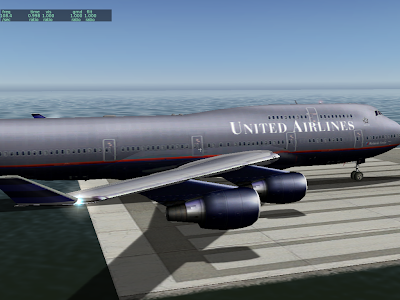
Here we have the default 747, as of 922. It’s a little bit tricky to tell what’s going on because the texture has been painted to look like there are lighting effects. But the white “specular hilights” on the engine nacelles are due to the sun position. Lighting is per-vertex and specular hilights are not separate.
Next we have the same plane in 930 without shaders:
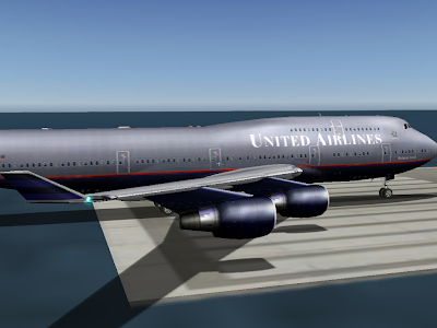
Note the increased brightness on the nacelles and fuselage. What’s happening is the hilights are no longer modulated by the texture, so they show up a bit more.
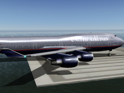
Finally, the plane in 930 with shaders. Now the hilights look smoother and much brighter. This is because the hilights are calculated on a per-pixel basis. Note how the hilights are small – smaller than the triangle size on the engines. We didn’t get the full “glare” effect before because the brightest part of the hilight did not land on a vertex at all, and was thus never seen.
Note that the change in specular hilight handling (moving to separate specular hilights) is a bit of a compatibility break. Previously authors could count on not having specular hilights on dark parts of a plane, even if they set the plane to be shiny.
I am not sure how we will ship the final version of 930. I have received very few (none, to be exact) complaints about dark surfaces appearing “too shiny”, and a lot of users like the new shiny look.
The alternative to the current scheme (specular hilights are separate by default) is to have this be a selectable feature. Older planes would look the same as they always did, but planes would have to be modified to make them look truly shiny.
ATTR_hard is the OBJ attribute that makes the geometry of an object mesh interact with X-Plane’s physics engine. ATTR_hard object has a long history of weird behavior, and its behavior in X-Plane 930 is no exception.
The History
- Before X-Plane 815, hard surfaces acted horizontal regardless of the actual OBJ geometry.
- From X-Plane 815-922, sloped hard surfaces work as expected, but vertical hard surfaces do not work. Animation is ignored for hard surfaces.
- Starting with X-Plane 930, animation commands affect hard surfaces. However, vertical surfaces still do not work, and an animated surface does not create friction under the plane.
(In other words, if you put the plane on a platform and move the platform horizontally, the plane will be pulled with the platform due to friction between the platform and the wheels.)
In all of these cases, what we have is a limited implementation that doesn’t correctly capture all expected behaviors. Why don’t we have a better implementation? There are two factors.
- In some cases a more correct implementation might take significantly more CPU power. It is important that we not raise the CPU requirements of X-Plane mid-version run.
- In some cases, we simply don’t have a better implementation coded yet. Remember that X-Plane is primarily a flight simulator. My pilot friends tell me that it is bad form to collide the airplane with anything during flight. So the goal of OBJ collisions is more to detect poor flying than to correctly model the resulting aftermath. X-Plane is not GTA4!
What Do You Do With a Buggy Feature?
Very simple: don’t use it if you can avoid it! I don’t mean “don’t use ATTR_hard” – it has legitimate uses. Rather I mean: don’t depend on the buggy behavior as a feature.
For example, before 930, animation would affect the drawn but not physical OBJ. I would say that given that bug, the only safe thing to do is to not animate hard objects. Animating hard objects to take advantage of the schism between drawing and physics would be assuming that the bug will stay buggy forever.
What Can You Do Now?
In X-Plane 930 hard object animation is a lot better than it used to be, but still not quite correct. The remaining limitations are:
- There is no friction. If you move a platform horizontally, the plane is not dragged along. So you can’t really build horizontal elevators. (You can build a platform that moves vertically and move the plane around that way.)
- There is still not support for vertical hard surfaces. Like before, to make a solid “wall”, make the wall thick and make the top of the wall hard. But bear in mind that the collision detection in this case is catastrophic; your plane will be heavily damaged by even minor contact with the wall. X-Plane doesn’t support horizontal collisions right now.
- Hard surfaces are ignored for vehicles. If you are replacing the car set, don’t add hard surfaces – it might turn out that some future implementation does look at them – if that happened, how would you know what the CPU hit is?
Even given this limitation, you can now make a building with limited access controlled by animation; using a “deck” for the roof and a hard surface for the tops of the walls and the doors (which are animated) you can control access.
It is true that in X-Plane 922, some programmer dialed down the effective range of VORs.
That programmer was me. (This is what happens when you let a non-pilot go poking at the nav code.)
The bug report was that a rather far away VOR could be received on the ground at KSFO; looking at the actual service volume, the notion that this could happen was crazy. I ended up tuning the distance calculation and also the “fudge factor”. The fudge factor is the increase in the service volume of VORs in the sim from the listed usable service volume (which is really more like a guaranteed minimum) that lives in the nav.dat file.
Here’s the real problem: VOR range has a lot to do with altitude, but X-Plane does not simulate shaped 3-d service volumes. I think we will, but probably not for 930. So for now we have to pick a fudge factor that is large enough to make IFR navigation work without allowing you to receive any VOR from any location.
Beta 3 is still a bit short for VOR range – beta 4 or 5 may improve things a bit.
Note that it is possible to change the service volume of navaids in the nav.dat file. For example, KBOS and KLAX both have extended localizers; the fudge factor for a localizer doesn’t have to be 5x to allow KLAX to have a 100 nm final; the nav.dat entry for KLAX includes this special case.
Cutting the next beta is a double-edged sword:
- Any beta that doesn’t have known bugs fixed is just not as good as it could be, and is putting buggy code in the field, where those bugs take away from testing.
- Sometimes bugs are severe enough that they occlude other testing (particularly if there is a crash bug).
X-Plane 930 Beta 3 will be out fairly soon. The biggest thing that is not fixed is the weird lighting on GeForce 6/7 hardware with pixel shaders on. It’s just my luck that we’d have a hardware-specific shader bug on the one chipset I don’t have right now. (I could pull my 9700 from the PC, but then I won’t be able to reproduce the evil “framebuffer incomplete” bug.)
We did find an intermittent crash during scenery load while flying – that’s the kind of thing we need to get into a new beta; we can’t tell what else is a real crash until that one gets cleared out of the way.
There is a crash bug that we haven’t fixed in beta 3: Austin and I have both seen a single, unreproducible crash during startup on Windows. If you have a crash during startup on Windows, please send a crash_log.txt with your bug report!
Posted in News
by
Ben Supnik |
I have been trying to put documentation on the X-Plane Wiki, and use this blog for announcements and “the inside story”, rather than letting the blog turn into a poor-man’s users manual. An aircraft developer asked me via email whether there was a blog entry on some of the pitfalls of the v9 panel lighting system. There is not, and the lighting system is under-documented. I will be working on improving the documents over the next few weeks, but the point of this blog entry is: “how did we get here?”
I am a huge fan of incremental software improvement. That’s the subject of another blog post (perhaps on another blog), but for now I’ll say this: all changes to the rendering engine since version 8.0 have been incremental ones, and yet if you were to look at the code, you wouldn’t see a series of band-aids taped on top of each other. Each incremental change leaves the rendering code “fully updated”, as if it had been written yesterday. I start each new scenery feature by first reshaping the existing code into the most useful form for what we want to have in the future, and then coding the new feature is relatively simple.
But this strategy has an Achilles heal; if the code being refactored has a public interface (whether it is a file format or programming API), then all of the intermediate steps in the journey become requirements for future products in order to maintain backward compatibility.
This is not a problem as long as the programmer knows where he is going. The danger comes when one of the intermediate steps is actually a step in the wrong direction, and becomes dead weight around a future design.
A Reasonable Progression: OBJ
The OBJ 800 file format has had a reasonable progression* since its birth in version 8. It has gained a number of new features, but each one has generalized and made more powerful previous ideas, such that “legacy behaviors” are not so painful. Some examples:
- Hard surfaces may now be decks (e.g. you can fly under them) or not, and you can specify what kind of hard surface you have. The original hard surface command was simply “it’s hard” or “it’s not”. But viewed under the lense of the new scenery system, that old hard surface command implicitly implied “the surface is smooth” and “the hard surface is not a deck”. So the new hard surface command is a more general version of the old one, which continues to work under the new system.
- Animations in version 9 can be key framed; in version 8 you simply specify start and end values. But start and end values are just like having two key frames. So viewed under the lense of the new scenery system, all animations are key framed; older objects always just have two key frames. The new key framed commands are a more powerful, more general version of the old ones.
I can’t say that the relatively pain-free evolution of OBJ files over the last 4 years comes from good design or genius on my part – in truth it’s probably just good luck. But I think one thing has helped me keep the new OBJ extensions relatively sane: most of them are conceived several months before they make it into X-Plane.
I have a scenery system to-do list that will last me at least another four years; most of it is filled with things that Sergio has asked for. This to-do list acts as sort of a road map for future scenery system extensions; for any possible OBJ change, I can look at it relative to the other todo items and ask: “is this extension going to play nicely with things to come?”
(As a side note, this is one of the reasons why there are not light maps in any of the X-Plane modeling formats. Light maps don’t play well with a number of other scenery system extensions. I want to resolve the conflict between these future additions before they go into the sim.)
Wandering In the Desert
By comparison, the evolution of the panel system in version 9 has been more like wandering in the desert than a straight line toward a goal. Repeatedly, I put features into the panel system without a clear roadmap of where we would end up or how they would work together. The result is what you see now when looking over the panel documents: complexity and chaos.
Basically there are several major changes to the panel system that affect each other in strange ways:
- A more complex lighting model on the 2-d panel in version 920. (That is, the 3 2-d spot lights, and generic instruments with back-lit, mechanical, or glass lighting.)
- A more complex lighting model in the 3-d cockpit in version 930. (That is, 3-d spot lights, ATTR_cocpkit_region and generic instruments with back-lit, mechanical, or glass lighting.)
- A separate panel used only to provide texture to the 3-d cockpit. (That is, the 3-d panel.)
The problem is the order that they were invented: first ATTR_cockpit_region, then the 3-d cockpit, then back-lit generic instruments, then 2-d spot lights, and then 3-d spot lights.
The result is two sources of confusion:
- Some combinations of features simply don’t work together. Since all of the features appear to be independent, I sometimes get bug reports on these. For example, you can’t use the 2-d spot lights on the 3-d panel. This is not a bug, it is by design! I will explain why some of these limits exist in future blog posts.
- Among the remaining combinations that do work together, there are a lot of choices about how to structure a plane – too many choices!
This second point is a tricky one: X-Plane has to continue to support whatever set of features was available for any given release (864, 900, 920, 930) so that older planes continue to work. But some of those combinations (e.g. the ones that exist in version 900) don’t make a lot of sense for new planes made in 930.
I am open to ideas on how to solve this. I intend to document a “correct formula” for a modern plane, perhaps with tutorials, on the Wiki. I am also considering programming Plane-Maker to flag unusual combinations of features as a warning when saving 930 planes.
Either way, I fear I’ve learned my lesson from the panel system: incremental improvement of code is only a good idea if the programmer knows where he is going! Next time I will use Google Maps. 🙂
* I suppose that whether you think the OBJ 800’s evolution has been reasonable depends on your standards for file formats. OBJ 800 absolutely does show growing pains. I would only say: consider the number of revisions and the change in the hardware platform OBJ 800 feeds when you consider its stretch marks.
I thought I had already blogged about this, but I can’t find the old posts, so here goes. The big question: why can’t we have “X” in the OBJ file format or as part of generic instruments?
I get a lot of requests for “more power” in the OBJ or generic instrument system – the ability to play sounds, to do simple math operations on datarefs, more show-hide filters, the ability for a generic instrument to change a dataref in response to another dataref instead of a mouse click.
And invariably I say “No! Go write a plugin!”, which I realize is a fairly rude thing to say to a non-programmer. First, let me explain why I say no, and then what we can do about this.
Keeping Systems Separate
These feature requests fall into two broad categories: “systems programming”, which is really anything that has a side effect (play a sound, change a dataref, apply some logic), and “visualization” (e.g. a user needs more flexibility to better visualize the sim’s state.
I definitely do not want any kind of “systems modeling” code inside OBJs or generic instruments. To give a trivial example: imagine that you could make a generic instrument that would set the generators to on when the landing gear is raised.
What then happens if this generic instrument is off the bottom of the screen when the landing gear is raised? Does the generic instrument get to perform its logic? Both OBJs and generic instruments are fundamentally “visualization” systems – both will short-circuit for performance when they are not visible. If we put systems modeling code into them, then the sim has to evaluate a potentially large number of otherwise unimportant (non-visible) objects and instruments to do system behaviors.
In computer programming, there is the notion of a “model-view-controller” design. The basic idea is to keep the code that changes the model, the model itself, and the code that lets the user see the data model, all separate. Keeping them separate keeps operation consistent – the model does not change its behavior depending on how you look at it, which is very important for consistent simulation.
So for all systems modeling, my answer is always the same: not in viewing code!
Expressions and Visualization
Some requests are simply requests for more visualization complexity – there is only so much you can do with key frames, animation, and a few filters.
I do have to admit that on some level, it is perfectly reasonable to ask for infinite power to visualize data in OBJs and generic instruments.
On the other hand, there would be a real cost to having programming-language complexity in what are otherwise relatively simple-to-use parts of X-Plane (e.g. the simplest model is just an export from ac3d…). My solution for both problems (systems and visualization) is a scripting system, but in the case of visualization, it is about not reinventing the wheel and keeping complexity limited to one place (the scripting system).
Scripting
Plugins have the power to solve all of these problems – they can change almost any aspect of the sim. But they are also very difficult to create; you need to be a programmer who knows a language like C or Pascal, and you need to know how to use the development tool for each platform you want to support. That’s a huge amount of specialized knowledge just to customize a few systems.
Basically we need to have a line in the sand. At some point, when the systems to visualize information (OBJ, generic instruments) are not powerful enough, we need to make programming easier, rather than make modeling and authoring more complex.
What we need is a scripting system. The scripting system would provide a relatively simple text-file syntax to do simple scripting of systems and instruments for airplanes.
Such a scripting system should be implemented as an open source plugin; it should not be built into X-Plane. The advantage of this would be:
- Anyone could improve or add features to such a scripting system, not just Austin and myself.
- People could freely customize the scripting system as needed for specific projects.
- By having the code be part of a plugin and not the sim, backward compatibility would be improved – even if the “official” version of the scripting plugin changed, you could always include an older version with your plane that worked exactly the way you want.
Who should work on this scripting system? I don’t know. Probably not me — I am not very good at making simple systems; see also what a complex disaster the panel and instrument system has become!
When a user requests that I add a feature to the generic instrument system, there is an implicit request – that Austin or I take programming time to do the feature. So for now I can only say that if/when I take time to do some of these feature requests, it will be in the form of a scripting system, not as extensions to the generic instrument and OBJ systems. This will give us better long-term compatibility and extensibility (via an open source plugin) and will keep systems modeling code separate from the visualization system.
X-Plane 930 has a lot in it – I will try to cover some of the details of the new features soon, but some immediate thoughts:
- X-Plane betas are open to anyone who wants to participate. You don’t have to sign up, you don’t have to be approved.
- If you would not be happy with a buggy, broken, weird, freaked out version of X-Plane, do not get the beta! Just wait and enjoy 922 – when 930 is debugged, it will be free for everyone.
- If you make a third party add-on for X-Plane and 930 breaks it…report it, don’t fix it! Give us a simple report about how your add-on used to work in 922 and is hosed in 930, and show us where to get the add-on. None of the new features in 930 should break 922 content. Pretty much all of them do nothing until you choose to use them.
- If you make a third party add-on, get on the new betas early; the earlier you report it, the earlier we can fix it.
- Don’t release third party add-ons for 930 until 930 goes final. Until 930 is final, all datarefs, SDK features, etc. are subject to change.
- Keep a copy of 922 around if you want to fly during early betas.
- Don’t use early 930 betas on critical files – make backup copies!
The first few betas are usually pretty rough…the main reason is that Laminar Research is a small company, and therefore we have a small number of computers; even though I have five machines in my office now (and I think 12 operating systems) there are plenty of combinations of software, hardware and drivers that our users have that we don’t have.
So if you try the beta and it just blows up…don’t panic! Report a bug, and we’ll try to get it working for your machine. The pixel shaders and low level video driver setup code have changed, which means working out the kinks on every hardware configuration out there. (Programmers sometimes call this “write once, debug everywhere”.)
With that in mind, there’s a lot of cool stuff in 930. Better 2-d panel filtering and per-pixel lighting should make the sim look better for just about everyone; other features like 3-d cockpit lighting will be of interest to airplane authors. I will be updating the X-Plane wiki to document how to use some of these new features over the next few days.
Posted in News
by
Ben Supnik |
A number of users have confirmed that the new ATI Catalyst 9-1 drivers fix the artifacts introduced with the 8-12 drivers! No need to stay back on the 8-11 drivers any more.
It’s nice to have this bug fixed – long time X-Plane users saw this as soon as they updated from 8-11 to 8-12 – they updated drivers and the sim got weird looking, so they just rolled their drivers back.
But a number of MSFS users have tried the X-Plane demo for the first time using 8-12 drivers and wondered how we could ship such a lousy product. The key, of course, is that MSFS uses DirectX drivers, while X-Plane uses OpenGL drivers, so the 8-12 drivers affected X-Plane but not MSFS.
I’ve been poking at the FRAMEBUFFER_INCOMPLETE messages that some people get. The best I have so far is: run with –no_fbos and –no_glsl (learn how
here). If you get this card and you have 2 GB of RAM, consider turning your rendering settings down a bit.
And 930? I got my last beta stopper fixed today, so it’s time for a scotch! I’ll post more on the beta tomorrow.


