My last post generated number of posts from both sides of the “hardware divide” (that’d be the have’s and have-not’s). I think everyone at least grasps that developer time is finite and features have to get prioritized at the cost of other features, even if not everyone agrees about what we should be coding.
I think the term “hardware divide” is the right one, because the hardware market has changed. Years ago when I bought myself a nice shiny new Dell (back when that wasn’t an idiotic idea) a medium-priced Dell had medium-priced hardware. Not only did I get a decently fast CPU (for the time), but I got a decent AGP bus, decent motherboard, etc. The machine wasn’t top-end, but it scaled.
When you look at any computer market, you need to consider what happens when consumers can no longer accept “more” and instead want “the same for cheaper”. This change in economics turns an industry on its head, and there are always winners and losers. (I have
claimed in the past that operating systems have turned that corner from “we want more” to “we want cheaper”, a shift that is very good for Linux and very bad for Microsoft.)
Desktop computers hit this point a while ago, and the result is that a typical non-gamer computer contains parts picked from the lower end of the current hardware menu. You’re more likely to see:
- Integrated graphics/graphics by the chipset-vendor.
- System memory used for VRAM.
- Slower bus speeds, or no graphics bus.
- GPU picked from the lowest end (with the fewest number of shader units).
- CPUs with less cache (this matters).
Someone commented a few days ago that computers would get more and more cores, and therefore multi-core scalability would be very important to fully utilizing a machine. I agree.
But: how many cores are those low-end PCs, aimed for general use (read: email, the web, text editing) going to have?
My guess is: not that many. Probably 2-4 at most.
These low end PCs are driven by one thing: price – the absence of VRAM or dedicated graphics hardware is all about bringing the hardware costs down – a $25 savings matters! In that situation, box-builders will want the cheapest CPU, and the cheapest CPUs will be the physically smallest ones, allowing for more chips on a wafer. A low-end PC will get no benefit from more than 4 cores – the intended use probably doesn’t even use one.*
Multiple cores are great because they give us a new way to benefit from smaller transistors (that is, by packing more cores on a chip, rather than clocking it faster, which has real limitations). But I think you’ll start to see the same kinds of gaps in CPU count that you see now with GPUs.
(In fact, the mechanics are very similar. The main differences between high-end and low-end GPUs of the same family are the number of parallel pixel pipelines – the low-end chip is often a high-end chip with a few defective pipelines disabled. Thus you can have a 4x or 8x performance difference due to parallel processing between siblings in a GPU family. Perhaps we’ll see the same idea with multi-core chips: build an 8-core chip, and if 4 of the cores fail, cut them out with the laser and sell it as a low-end chip.)
* One advantage of multiple cores is that they can take the place of dedicated hardware. For example, there is no penalty for doing CPU-based audio mixing (rather than having a DSP chip on the sound card) if the mixing happens on a second core. Being able to replace a dedicated component with a percentage of a core is a win in getting total hardware cost down, particularly if you were going to have the second core already.
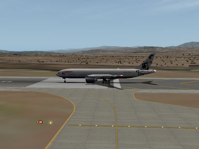
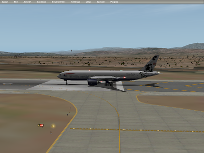
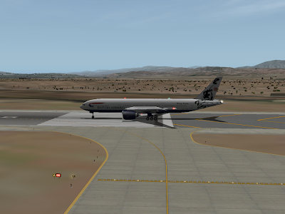
With X-Plane 920 RC1, the user can now control how smooth taxiway curves look. More smoothing looks better, but can slow frame-rate.
Below are four pictures of KSBD (which has good, sparse vertices) at the four rendering settings.

In my post on 64-bit computing and X-Plane, there’s a point that’s implicit: there is a cost (in development time) to adopting any new technology, and it takes away from other things. I’ve been slow to work on 64-bit X-Plane because it would take away from things like texture paging and generic instruments. Similarly, there is a cost every time we do a build to supporting more configurations, so we pay for 64-bit continuously, by supporting six platforms instead of 3 (3 operating systems x 2 “bit-widths” of 32 and 64 bits).
We have a similar problem with graphics hardware, but it’s even more evil. Moore’s Law more or less says that in a given period of time, computer technology gets twice as fast. In the case of graphics cards, each generation of cards (coming out about every 12-18 months) is twice as fast as the last.
This has some scary implications for X-Plane. Consider these stats for video cards (taken from Wikipedia):
Card      Date        fill rate       Bus         Memory bw
GF3       01Q4        1920 MT/S       4x          8 GB/S
GF4 Ti    03Q1        2400 MT/S       8x          10 GB/S
GF5950    03Q4        3800 MT/S       8x          30.4 GB/S
GF6800    04Q2        7200 MT/S       PCIe16      35.2 GB/S
GF7900    06Q1        15600 MT/S      PCIe16      51.2 GB/S
GF8800    06Q4        36800 MT/S      PCIe16      86.4 GB/S
GF9800    08Q2        47232 MT/S      PCIe16/2    70.4 GB/S
Let’s assume we support any video card in the last 5 years (in truth we support more than that). The difference between the best card and the oldest in w006 was 13,680 MT of fill rate.
Now in 2008 the difference is 43,432 megatexels per second!
In other words, the gap between the best and worst cards we might support is over 3x larger in only 3 years!
This is no surprise – since cards get twice as fast with every revision, the gap for a given number of generations also gets twice as wide.
What this means for us, programming X-Plane, is that coming up with a single simulator that runs on the very best and worst hardware is becoming increasingly more difficult, as the performance gains at the high end run away.
As 920 beta finishes up, I am working on some WED features. Future WED updates will be small and more frequent; I think it’s more useful to get at least some features into WED quickly, rather than holding them until I have a huge update.
So this list is short – that doesn’t mean that other features won’t happen – they just won’t happen as soon. In particular, I am very aware that WED needs better taxiway sign editing and better polygon editing. Those will have to wait though.
WED 1.1 will provide overlay editing. WED will not be a replacement for overlay editor – Marginal has done a really great job with his tools. However, having overlay editing in WED will allow people making airports to see complete apt.dat 850 data and overlay data at the same time. This is particularly useful for authors making custom scenery where the apt.dat format is augmented with custom DSF overlay pavement and lines.*
WED 1.1 will have 3 features:
- Ability to edit these DSF overlay types: object placements, facades, forests, object strings, draped lines, and draped polygons (both tiled and textured with ST coordinates).
- Very limited preview of those types. I know you will be able to see the texture for a draped polygon for orthophoto placement. I do not know if I will even have OBJ preview in 1.1. Editing will not be WYSIWYG. It will be more CAD-like.
- Import and export of DSF overlay types to DSF overlay files.
Note that while roads and beaches are technically allowed in overlays, they are not on the list. The reason is that right now both of them require elevation data in the road and beach itself. Since WED doesn’t have a base mesh, it can’t sanely provide this information.
Eventually we will have some way to “drape” roads – at that point it will make sense to provide WED road editing too. But let’s not delay at least some overlay editing that long!
I don’t know exactly how long this work will take – my rough guesstimate is about 2 weeks. But…that depends on my working on WED for two weeks straight without interruption!
* Every type of element in apt.dat can also be created with custom-provided artwork and an overlay DSF — draped polygons for taxiways, draped lines for taxiway lines, object strings for taxiway lights, etc. The idea is to provide a way for authors who want to extend realism beyond the scope of apt.dat 850 to insert custom artwork. Apt.dat 850 is not a modeling format, so you cannot provide PNG files with it.
If you look at the LOWI demo area, you’ll see that some of the pavement in that layout is in the apt.dat file, but some pavement is in the DSF overlay. Creating this demo area required a bunch of DSF2Text hacking by Sergio and myself. With WED 1.1 it will be possible to do this completely using WED.
I don’t usually blog about plugin issues, but this one falls into limbo, somewhere between plugins, aircraft design and OBJ animation. This is written for plugin developers; if you don’t write plugins, you can tune out.
Plugin Drawing
Plugin drawing is documented in a few tech notes – I strongly recommend reading them all.
The basic idea is this: to draw in a plugin, you register a callback. X-Plane tells you “it’s time to draw” and you draw.
The first rule of drawing callbacks is: you only draw. You don’t do anything else.
The second rule of drawing callbacks is: you only draw. You don’t do anything else.
There are a number of good reasons for this.
- You don’t know how many times, or in what order the callbacks will be called! You might be called four times per frame or none. So doing flight model calculations in a draw callback is a bad idea.
- Drawing has to be fast. In the drawing code we are trying to stuff the GPU to the gills with work to do. Drawing time is not a good time to go off and do other expensive calculations.When we look at the interaction of the CPU and GPU, we know that the flight model takes some pure CPU time, and we can improve efficiency by queuing an expensive OpenGL operation before we hit that CPU-only phase. If your plugin is doing its real calculations during draw time, our pipelining gets thrown off.
- We’re continually increasing the parallelism of the sim via threads to take advantage of multiple cores. But plugins are single threaded by definition. This means that plugin interaction points will (in the future sim) halt parallel operation and slow overall performance. When we design parallel operation, we can try to optimize our design to avoid this “halt” case, but if you are doing something strange (like flight calculations in a draw loop) you’re more likely to fall off the “fast path”.
Surprise
Now here’s the surprising thing: your dataref callback is actually a drawing callback, sort of!
Object datarefs are called back during object drawing. Therefore they have all of the above problems that drawing callbacks have. Here is my recommendation:
If you create a custom dataref that is used by an OBJ for animation, return a cached value from a variable in the dataref, and update that variable from the flight loop.
This avoids the risk of your “systems modeling” code being called more than once per frame, etc.
When you update X-Plane, it scans about 10,000 files before it runs the update. This scan checks every single byte of every file. As a result, it’s a little bit slow – it takes a few minutes.
With the new installer, when you add and remove scenery, we do the same scan on the installed scenery. This scan is very slow – 78 GB is a lot of data!
When the next installer comes out (2.05, which will be cut after 920 goes final), the add-remove scenery function will do a quick scan to see what files exist. This is a lot faster – even with full scenery the scan takes only 10-20 seconds on a slower computer.
I can’t pull the same trick for updates – we need to detect any possible defect in a file during update to ensure that the install is correct!
We get a number of questions about whether X-Plane takes advantage of 64-bit CPUs. The short answer is: “no, not yet”, but here’s the details.
Some of the people who ask are Linux users who haven’t been able to set up 32-bit compatibility libraries for their 64-bit Linux distribution. To me, this is a portability request, e.g. can you make X-Plane work on yet another operating system. I don’t view this as a high priority because you can run X-Plane on a 64-bit operating system using 32-bit compatibility libraries for a number of distros. Linux comes in a million flavors and we can’t support them all.
Other users ask about 64-bit because they have 64-bit CPUs (and possibly paid more for a 64-bit operating system) and want to know when they get some benefit for their money. But…is 64-bits actually useful?
A 64-bit CPU is one that can deal with larger integral numbers – as a result it can access more memory than 4 GB, and it can do math with very large integer numbers more efficiently. 64-bit CPUs also have some architectural differences that are theoretically beneficial.
Is It Faster?
Joshua tried building an experimental 64-bit version of X-Plane for Linux when he first got his 64-bit AMD box and he found…
…no performance benefit at all.
Doh! This actually isn’t surprising.
- X-Plane doesn’t use very large integral number math. X-Plane uses a lot of floating point math.
- The biggest time-sinks for the CPU in X-Plane are talking to the driver and sorting through piles of scenery. The later task requires a lot of logic and memory access — neither of which work any better on a 64-bit CPU.
So the short answer is: you’re not going to get a fps boost from 64 bit. Sorry.
Memory, Memory, Memory
Now 64-bits is useful because a 64-bit app (on a 64-bit OS and 64-bit CPU) can access more than 3 GB of RAM. We’re reaching the point where a lot of users have 4 GB of RAM and a machine that could be using all of it. While I’ve been dragging my feat on the move, someday we will support 64-bits and X-Plane will be able to use more memory.
But in the meantime, I’ve been doing everything I can to reduce the amount of memory X-Plane uses. This is because optimizing memory usage benefits all users, while 64-bits only helps users with a 64-bit OS and a 64-bit CPU.
I believe that we’ll reach a point where 64-bits is useful for users who want to use a ton of add-ons simultaneously. But the out-of-box X-Plane configuration needs to work with much less memory than 4 GB.
I’m back from vacation and trying to catch up on email and close out 920. I’ve received a number of emails regarding the 3-d cockpit, the big questions being:
- What can I do about the lousy lighting for 3-d object textures and 3-d panel textures via ATTR_cockpit_region?
- Can I use the new 2-d panel spot lights in the 3-d cockpit?
The answer is unfortunately “not much for now” and “no”. Let me explain what’s going on with the 3-d cockpit and what we’re thinking for a long term strategy.
First, I try to organize my feature work around one part of the sim for each patch. 920 is a bit too big of a patch for us (featuring both a lot of cockpit/instrument work and some big rendering engine changes). Austin has been on the road a lot this year, and in his absence I went a little nutty. I wanted to do some work on the 3-d cockpit, but it’s different code, and with 920 in beta so long, this work will have to wait.
3-d Lighting
Our long term approach to the 3-d cockpit is “real 3-d lighting”. By that I mean: multiple light sources, acting on all of the cockpit geometry based on 3-d positioning. This means a few things:
- Providing some way to specify multiple light sources inside the cockpit, as well as how they are controlled (e.g. how do you dim the flood light)?
- Specifying which attached objects are considered part of the interior of the plane vs. the exterior.
- Providing a way to provide emissive lighting vs. elements that must be lit by light sources.
The 3-d cockpit lighting environment must work the same for the panel texture and object textures. This is necessary to keep the brightness of the finished cockpit consistent between the two textures sources. With the current 3-d system (e.g. what you can do in 864) often the brightness of the panel texture and the rest of the object don’t match.
To this end, ATTR_cockpit_region, which is targeted at the new system, gives you the same lighting model for the object texture and panel texture. Now that model isn’t very useful right now, but it will get better with future patches, and it will always be consistent.
Why Not 2-D Panel Lighting
We can’t use the new 2-d panel lighting features (spot lights), etc. because they are not scalable. Most of the advanced 3-d cockpits I have looked at use a lot of textures, quite possibly several 1024×1024 object textures, as well as a panel texture.
Now the panel texture is very expensive, so there is a penalty for letting it be any bigger than necessary. Given this, we’d only have two options:
- Provide the 2-d spot light features on the OBJ textures, effectively making them dynamic. This would be very expensive, performance-wise.
- Have authors only use one huge panel texture. This would limit them to 2048×2048 and be really slow.
If we don’t provide the spot lighting features for all panel textures then we have the problem of inconsistent lighting, which makes the feature fairly useless.
So instead I have withheld spot lighting (and _LIT replacement textures) from the 3-d panel; the cockpit object will instead end up featuring real 3-d light sources to create these kinds of effects in a 3-d correct manner.
The idea here is to avoid providing features that will be unnecessary, inferior, slow, or unsupportable in the future. Otherwise such a “stop-gap” measure would just end up breaking existing airplanes.
So for now, the 864 system for 3-d cockpits still works as it always did. It will be at least one more patch before 3-d cockpits get a serious upgrade.
It’s that time of the year again…I’ll be out of the office next week, and more importantly, away from all cell and email contact.
Austin and Randy will be at EAA – stop by and say hi if you’re there. Once Austin gets back, the last few betas should resume – we’re close to an RC on 920 but not quite there.
I just found two bugs in the scenery system in beta 7 (both will be fixed in beta 8):
- If an object had a blank TEXTURE statement with no trailing white space (this is legal in OBJ8, at least I think) the sim would crash when it rendered the object.
- DDS-based terrain textures with the new paging system would show junk when they were far away.
One of our users did the right thing: even though it wasn’t his scenery, he reported the problem and sent me the packages, rather than fixing the problem and going on.
My goal with scenery is to avoid regression bugs – that is, if it works in 900, it should work in 920. So I was glad to get these reports. I cringe when I read posts where people report “fixing” problems with content that are new to 920. Those are my bugs to fix!


