Panels and airplanes aren’t really my thing. But we’re using the OBJ engine more and more in aircraft, blurring the lines between scenery code and aircraft code.
In X-Plane you can actually use the panel texture in any object. Pleaes don’t do this! There are two cases:
Airplane Objects
With X-Plane 860 you can attach many objects to an aircraft. But…you should only use the panel texture in the cockpit object.
The cockpit object is special! It is the only object that gets mouse-click tested. In the future we will decide how much of the 2-d panel to render to a texure (for the 3-d cockpit) based on the cockpit object. So…don’t use the panel texture in your other aircraft objects. Put your panel-textured triangles in the panel object.
(You should do this anyway; switching to the panel texture creates a new batch*, so using it in a lot of separate objects is bad for framerate.)
Scenery Objects
Technically you can also use the panel texture in scenery objects. This is really just a big hack — all of the issues with optimzation apply to this case, plus: how can you even know the layout of the panel texture in scenery? Don’t do this!
* “Batch” is the technical term in the game development and authoring world for a set of triangles that can be drawn by the graphics card via single CPU command. While graphics cards can process tons and tons of triangles, the number of batches they can process is limited by CPU and bus speed, which advance much more slowly. Generally the number of batches is the limiting factor in X-Plane’s framerate.
It’s easy to see how many batches your OBJ8 contains: open the file and count the number of “TRIS” and “LINES” commands at the end. Ignoring lights, the sum of the TRIS and LINES commands is the number of batches! (HINT: fewer is better, and only one batch is great!)
Ari asked a good question regarding sloped runways and the new apt.dat 850 format:
Am I understanding it right that airport taxiways, ramps and runways are from now on going to be merged into one big mesh, instead of bunch of rectangle pieces overlapping each other? If yes, will this finally allow us turning on sloped runways option in X-Plane without any of the current side effects?
This brings up some interesting questions. First the most basic answer:
- apt.dat 850 prrovides curves, irregular taxiway shapes, which will allow you to create complex taxiway shapes with only one piece of pavement, rather than many overlapping ones.
- X-Plane still honors the order of apt.dat 850 for drawing, so you can also overlap and get visually consistent results.
- We recommend using a smaller number of curved taxiways rather than many overlapping rectangular ones because X-Plane can handles this case more efficiently. It is not necessary to build the entire airport out of one taxiway though.
Now the second part of the second of this question is a little more complex, because the cause of bumps in the scenery changed.
Bumpy Runways in the Good Old Days
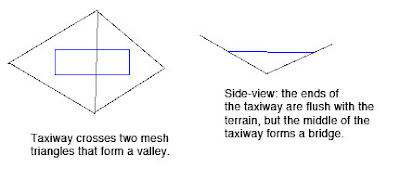
Back in X-Plane 806 there was a fundamental problem with the way we did sloped runways that made them virtually unusable: while the corners of each rectangular piece of pavement would sit directly on the terrain (no matter what the terrain’s slope), the area of the taixway was formed by a flat plane. This means that the middle of the taxiway might be above or below the terrain.
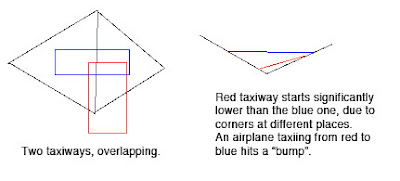
Now the real problem comes when we have two taxiways that overlap. Because they are only aligned to the terrain at their corners and not centers, there may be differences in their height when one taxiway’s corner hits another taxiway’s center (which happens a lot). As the airplane travels from one taxiway to another, the elevation of the ground changes instantly, inducing a major jolt to the suspension. At high speeds these damage the airplane’s suspension.
Bumpy Runways Now
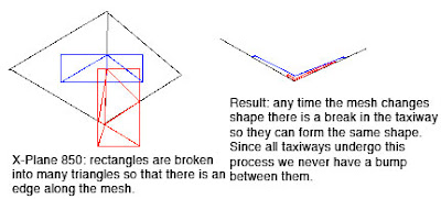
In X-Plane 850, we break all runways and taxiways (new and old) into multiple pieces each tiem the terrain underneath them has an edge. The resulting taxiways are then aligned to the mesh at their corners. But since no taxiway center goes over a mesh corner, the taxiway “hugs” the mesh perfectly. And since all taxiways hug the mesh in the same way, there is never a height gap between taxiways.
It’s the Mesh, Stupid
So why do we still have bumps in X-Plane 850 if we so carefully make sure the taxiways exactly reflect the mesh height? Well, you’re effectively driving on the terrain, so any bumps are ones from the terrain. Simply put, even with the new system the usability of sloped runways is only as good as the underlying terrain.
Now our meshes come from SRTM data, which is radar data – it naturally has a certain level of noise and “speckle” which makes it pretty unusable for airports…airplanes are very sensitive to even small bumps during takeoff.
We attempt to “condition” the elevation data for airport use, smoothing out hills and bumps. Unfortunately our algorithm doesn’t always work right. The X-Plane 8 US scenery was way too bumpy to be usable. The 7-DVD set is better, but still makes bumpy airports in a few cases:
- If there was no airport in the apt.dat file at the time of scenery creation, no conditioning was applied, and the underlying terrain is probably inappropriate for draping.
- The scenery creator has a bug that causes airport flattening to fail when it’s very close to water. For example, the big bump in the runway at KLGA is due to a water-airport interaction.
- I think that flattening across DSF tiles can have problems too.
If you’ve been thinking — wow, the diagram for 850 has a lot more triangles (10 vs 4) than the one for 806, you are right. Fortunately, the number of triangles, all part of one taxiway, in an airport layout, doesn’t really affect frame-rate, since this is handled by the GPU.
But this is also a case where a few curved polygons can be much more efficient than several overlapping ones – when we cut up the taxiway based on the mesh, if there is ovelapping pavement, each overlapping taxiway must be cut, multiplying the effects of the mesh on triangle count.
It also turns out that in the real case this is somewhat moot: because X-Plane smooths the airports and then induces triangle borders around the edge of the airport. Since the interior area is so flat, it doesn’t require a lot of triangles, and therefore the trianglse inside an airport tend to be big, so the number of times we have to cut an actual layout is quite small.
Mighty Mighty Bostones? Anyone? Nevermind. Anyway…
…some pictures of WED. (These were taken on a Macintosh, but it looks almost the same on Windows except for the title bars of the windows.)
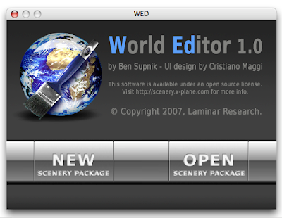
This is the startup window. WED can edit multiple scenery packages (in multiple windows) but does not let you edit a scenery package until you create and name it. So we show this window when you startup to let you choose between a new or existing project.
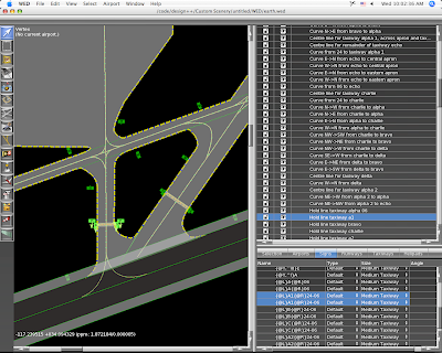
The left side is the map view, which provides draggable editing of any part of an apt.dat file. This is part of Aussie’s KSBD layout, which is part of the X-Plane demo. The right side provides a hiearchy-structure view (top) and more detailed editing or properties (bottom).
With the vertex tool, we can drag control handles for any selected entity.
The map view is a “structural” view, not a photorealistic one. The markings on the lines and pavement color change to reflect the settings you pick, but WED does not attempt to reproduce the final result in X-Plane.
Wiht the marquee tool, we get a rectangular edit box around the selection and can thus resize or move whole sets of entities at once.
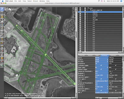
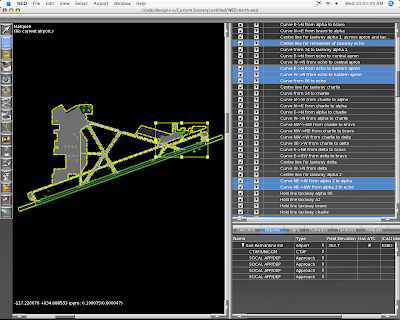
This is KBOS from 860 imported into WED. WED will import 810 or 850 layouts, but only exports 850 layouts. (It can thus be used as a simple converter.) That background image is automatically downloaded from terraserver and updated as you zoom and scroll the map. Unfortunately terraserver only covers the US; where there is no coverage you can import any BMP, PNG, JPEG or TIFF file and set it as a background image.
Posted in Tools
by
Ben Supnik |
A long time ago I posted a picture of my immediate supervisor. I am pleased to announce that the home office has brought on Cecelia to help consult on future X-Plane development. Here she is:

A meeting of the management team:

Since before I’ve been involved in X-Plane, scenery has been broken into tiles. You know the naming scheme…+42-072.XXX is some kind of file for Boston. Perhaps it’s a .env or a .dsf, but what is unchanged is that the world is broken up into bite-sized pieces.
Tiling is very necessary for X-Plane…it allows the sim to rapidly load only the information we are interested in. The world is too big to go fishing for the relatively small amount of data that is loaded at one time.
The source data that is used to build global scenery is also tiled – if you look at the SRTM files, they often have names like N42W072. It’s no surprise that global data requires tiling to make it manageable.
When we produce global scenery, we work on a per-tile basis. We load the raw tiled data* into source XES files (one per tile), then process and convert that XES file into a DSF. By working one tile at a time, we limit how much RAM we need.
But if you used WorldMaker on an airport or city that spanned a tile boundary, you know how annoying tiling can be. With WorldMaker you couldn’t see both halves of an airport at once.
WED will not use tiles. For custom scenery packages, the total data is not so large that we have to tile. When you work on a scenery package in WED, you work on the entire package at once as a single seamless workspace. When you export your work, WED will split the data into tiles as needed. This will mean:
- You do not have to decide in advance where you are going to work. All scenery packages cover the entire planet, and DSFs are created only as needed.
- You will be able to work on more than one “tile” of area at a time, because there are no tiles.
- You will be able to work on airports that span tile boundaries seamlessly.
I just finished fixing some bugs in WED regarding the hierarchy view. (To get a sense of what a hierarchy view is like, try AC3D…)
In WED, the contents of your airport layout are viewed in a hierarchy view. This is where you reorder your runways and rename entities. You can also group entities (as many times as you want) to help organize your layouts. (The groups will not be visible in the final apt.dat.)
An airport is, in a way, sort of a super-group…it’s a group of “stuff” (runways, taxiways, etc.) plus it has its own information.
But this leads to some tricky situations:
- You can’t have an airport inside another airport.
- You can’t have a runway outside an airport.
The result is that there are a number of grouping and drag & drop combinations in the hierarchy that are simply illegal. Cris and I debated this a bit and what we have now is: commands that would produce illegal results simply cannot be executed. (That is, the group command is grayed out if the new group would violate these rules, and the drag & drop won’t show a legal drop if the new order would violate these rules.)
Once we get into beta we’ll see how well this works. The alternatives include:
- Putting up a specific error message when an illegal configuration is made (annoying).
- Allowing illegal configurations and putting up an error message on export (by this time the whole file layout could be pretty badly messed up).
- Attempting to silently export the illegal configuration (unpredictable – there’s really no good way to export an airport inside an airport).
Also, I am sure there are some illegal configurations I have missed…we’ll have to catch those in beta too.
Posted in Tools
by
Ben Supnik |
The new beta of the AC3D export plugin is posted here. There are a bunch of bug fixes, but the two big ones are:
Texture paths are exported without relative directories. This was a new “feature” in the first beta, but virtually everyone said that exporting relative paths was both confusing and annoying. The plugin is now back the way it used to be. (If you need a relative path, there is a “prefix” path that you can specify in the preferences that will be prepended before all textures.)
The popup menu for datarefs has been replaced by a combo-box. This has three advantages:
- The popup can be built a lot faster.
- You can type custom datarefs into the combo box.
- It doesn’t crash.
Here’s a tip: if you type a part of a dataref into the combo box and then open it, only the matching datarefs are shown. Try typing “flightmodel” into the combo box and then opening it.
“Directories” of datarefs are shown first. So from flightmodel you can pick sim/flightmodel/position and then re-click. Now all of the position datarefs are shown. In this way you can navigate through all datarefs.
You can also use wild-cards in the combo-box. If you search for sim/flightmodel*x you will find all of the datarefs beginning with sim/flightmodel and ending with x. Note that when you use * your pattern must match the entire dataref.
(To search for all datarefs containing flightmodel and local with some text between them, you cannot just use flightmodel*local. You need to use *flightmodel*local*.)
First, I just want to be clear: I am not announcing any future features for the scenery tools. I am not saying when they will be released, and I am not saying what they will do, because honestly I do not know. There have been too many cases when users have emailed me and said either “I thought you guys were going to do X” or “you guys promised you were going to do X”, so now I am officially paranoid.
So this blog post is not about what the future scenery tools will do – it is simply a discussion of the difference between editing source data and compiled DSFs.
When we make the global scenery, we start with a bunch of source data that roughly consists of: road maps, coastlines, elevation, landuse, climate data, airport locations, etc. When we build a DSF out of it, we “bake” these items together into a single file. During this baking process, our tools apply some “integration effects”. Here are a few of the more obvious examples:
- Terrain under airports is forced to be an airport grass texture, appropriate for local climate data.
- Roads are removed from airport areas.
- Intersections are computed for highways – that is, a highway and city street form an overpass, but two city streets become a real intersection.
- Generated Buildings are put around the roads, not under them.
- Buildings are oriented to “face” the slope of the ground they are under, based on their shape.
That’s not a complete list, but it gives you an idea of some of what goes into making a DSF. All of this information is precomputed and represented in the final DSF. But consider this last point: the DSF contains the actual orientation (north/south/east/west) of each building. It does not contain the slope underneath the building and it contains no information about which buildings need reorientation. In other words, the results of the process, not the inputs to the process, are present.
So consider what would happen if you could simply edit the data in the DSF:
- If you moved an airport, the airport grass would stay in its own location.
- If you moved an airport over a road, the road would still be there.
- If you changed a city street to a highway, it would not form an overpass.
- If you moved a road on top of a generated building, the building would remain in place.
- If you changed the ground elevation, buildings would not change their orientation to face the new slope.
If you changed the source data and re-ran the DSF building process, these effects would occur. But remember, we need elevation, land use, etc. to build a DSF from scratch, and the DSF itself doesn’t contain its source data.
So we have two possible strategies for editing DSFs:
- We could build a DSF “retouching” tool that let us make very small changes to the existing DSF without having any source data. None of these effects would “work” so authors would have to make very small changes and then hand-fix any problems that appeared.
- We could build a DSF “rebuilding” tool that let authors make new DSFs from source data. All of the effects would look good, but authors would have to get some of the source data. (We could post our source data, or provide links to places where it can be downloaded.)
Note that we can’t have our cake and eat it…we cannot get the “integration effects” listed above unless we go back to the source data. If I can stretch my cake metaphor to the breaking point, once we make our cake, we can’t easily remove the flour and add another egg – we need to start over with the raw ingredients.
Which strategy will the scenery tools use? I don’t know yet. I am focusing on airport and overlay editing, which sidestep this issue a bit (we can easily edit an apt.dat 850 or overlay from the final product). We may do a bit of both strategies – it depends on what users want and what we can code efficiently.
Why don’t the finished DSFs contain everything we need to edit them? The answer is size. The finished global scenery was about 56 GB of DSF. When I last checked, the raw data that forms the DSFs was at least 100 GB or more. So for each DVD we shipped of scenery, we’d have to ship two more DVDs of source data, for a 21 DVD set, most of which wouldn’t be useful to most users.
That take the longest to program. This may surprise non-programmers, but won’t surprise anyone who has done UI development before.
Example: in WED, there is a spreadsheet-like view (the “property” view) that shows text-based information, usually with a list of runways or taxiways in one direction and different aspects of them (name, displaced threshhold length, surface, etc.) on the other.
In WED, if you press the tab key while editing text, WED will move to the next editable field, first across, then down. Furthermore, it will scroll the view as needed so you don’t need to adjust the scrollbars while working. The result is that you can, for example, use the mouse to select all of your taxiways, and then rename every single one of them from the keyboard with the tab key without ever going back to the mouse.
It’s a small UI feature that can make a big difference in how long it takes to work on a project, and takes surprisingly long to code.
Posted in Tools
by
Ben Supnik |
A user reported a bug: the 3-d buildings in all parts of the world outside the United States* are European-style, even in Australia, Canada, China, etc.
It takes two things to see 3-d objects in X-Plane:
- Location data in the DSF you are flying over.
- 3-d models (stored in OBJ files) that match the definitions called for by the location data.
Now we have location data for our “generic” objects (objects that are placed pseudo-randomly based on local topography and roads, to synthesize cities) for all urban areas that are covered by the 7-DVD global scenery set. But we only have two sets of artwork: a set of US-style buildings for use in the US, and a set of European-style buildings for the rest of the world.
So we had an unfortunate dilemma. Either we could have European style buildings everywhere, which looks funny, but at least it’s 3-d. Or we could use the European-style buildings only in Europe and have no 3-d at all everywhere else. Both options make some users unhappy and neither is very good. We chose to have the European buildings everywhere – my guess is that it generated slightly less complaints.
Well, the silver lining is: it’s actually really easy to remove the European-style builldings from the rest of the world (Canada, Australia, China, Russia, Africa, etc.). All you have to do is make a custom scenery pack that applies to the regions where you don’t want the buildings and maps them to a blank object. I have built such a custom scenery pack and posted it here. If you install this scenery pack, then Canada will be devoid of 3-d, but at least there won’t be mismatching architecture.
This begs the question: why not use the US buildings to populate some of those regions? The answer is that the US buildings are built to a different spec than the European ones, because the road grid data for the US is more detailed than the rest of the world. So amongst our current artwork, only the European buildings will work globally.
* When I refer to the United States, I really mean the continental United States. Sorry to everyone in the beautiful states of Hawaii and Alaska. This is just an artifact of how the data was imported – I could not get the Census data for Hawaii, Alaska, or the territories to import, so I reverted to the generic “global” data.


