I was going to post some pictures of the newly fixed “auto-vary” feature, but before I can do that in a way that makes any sense, I need to explain how X-Plane deals with texture repetition.
Texture repetition is the inevitable result of using “landuse-style” texturing (that is, a repeating single texture representing a type of land). Typical X-Plane land use textures are 1024 x 1024 at max res and repeat about every 3-5 km. Unfortunately, our brains are pattern-recognizing machines, and the result of this texturing scheme is that the “grid lines” of texture placement become apparent over wide views.
We use a number of techniques to minimize this problem.
Lots of Land Uses
Our main tool to combat repetition is to not use a given land use for too large of an area. This has the advantage of efficiently using the entire set of textures, and (because terrain textures change based on an irregular grid, based on elevation) the changes to textures are both irregular in shape and “plausible” in placement.
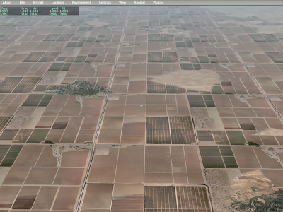
In this picture, you can see that the urban residential land use has been interrupted by various forest and grass textures. This is intentional – Sergio tuned hte land use rules to make sure that we wouldn’t have large regions of one land use type. Those blobs match the irregular grid, which gets its shape from the terrain’s elevation.
Variation
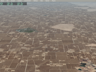
In the above picture, you can still see the repeating grid of the residential terrain; observe the right side – you’ll see the same repeating vertical pattern of road repeating over and over. In order to further hide repetition, we use the same texture multiple times, but in offset locations.
Here you can see that the vertical line on the right side has been broken up a bit.
More VRAM
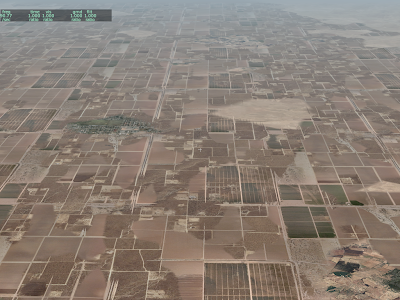
In some cases, a terrain covers such large areas despite the rule set (e.g. for really flat areas) that we use two separate textures and can vary between them. Here you can see both input textures for our dry square crop land use, as well as the combined results.
In summary, we have three techniques:
- Add more rules to prevent large spans of a single land-use.
- Use a texture with multiple offsets (variation)
- Use two textures and vary between them.
Yesterday I described how triangles and meshes can be optimized and hypothesized that building OBJs carefully could improve vertex throughput. Having looked at some numbers today, I think the potential for framerate improvement isn’t that great…an improvement would come from cache utilization (post vertex shader), and our cache usage seems to be pretty good already.
Simulating a FIFO vertex cache with 16 vertices (an average number – very old hardware might have 8 or 12, and newer hardware has at least 24 slots) I found that we miss the cache preventably around 15% of the time (using a random set of OBJs from LOWI to test) – sometimes we really missed bad (20-25%) but a lot of the time the miss rate might be as low as 5%.
What these numbers mean is that at the very best, index optimizations in OBJs to improve vertex throughput might only improve vertex processing by about 15% (with the FPS improvement being less, since vertex throughput isn’t the only thing that slows us down).
In other words, if I solve the cache problem perfectly (which may be impossible) we get at best 15%.
So this could be a nice optimization (every 5% win counts, and they matter if you can improve fps by 5% over and over) but cache utilization isn’t going to change the nature of what you can model with an OBJ, because our cache utilization is already pretty good.
Have a Happy Thanksgiving!
I’ve been looking a bit at triangle optimization – first some terminology:
- Indexed triangles means that the vertices in a mesh are referred to by index numbers. This is the scheme OBJ8 uses. The advantage of indexing is that if a single vertex is used by many triangles (that share a corner) you only have to include the vertex data once, and then use that data many times by index. (The savings from indexing depend on how often vertices are shared.)
- Triangle strips are strips of triangles sharing common edges. Because triangles in strips share so many common vertices, they can be stored in a compact form, for a savings of almost 3x.
Back in the old days, triangle strips were critical for performance (hence the presence of strips in the OBJ2 and OBJ7 formats). However with modern hardware, indexing is more efficient – the slight increase in data size (due to the index) isn’t as expensive as the cost of specifying “we’re done with one strip, start the next one”. (Consider that if we use indexed triangles, we can submit all triangles in one batch – with strips, we need one batch per strip.) Thus OBJ8 uses indexing and doesn’t provide any strip primitives.
There is one other concept to be aware of: cache utilization. Graphics cards remember the last few vertices they processed, so if a mesh repeats a vertex shortly after using it, the graphics card can save work. Triangle strips naturally use a cache somewhat well because vertices occur in close succession.
Strips and DSF
DSF allows for triangle strips (and triangle fans) as a space-saving measure. Even with indexing, the indices can be compressed if strips and fans are used, and with DSF, file size was a very high priority.
When the DSF file is loaded, the data is rebuilt into indexed triangles (and reindexed – the DSF internal structures don’t provide as good indexing as the DSF loader can create) – in version 803 we first started using indexed triangles and found it to be a big win.
MeshTool will generate triangle fans (as a space saving measure) – if you build a DSF by hand (using DSF2Text), use strips/fans to compress file size.
Because DSF focuses on file size, the quality of mesh output is a function of the DSF loader, which has to run while flying. So while I can imagine some improvements in future performance, I don’t expect to be able to get huge wins because the very best mesh optimizing algorithms are much too slow for real-time use.
The DSF loader already produces full indexing and preserves cache utilization from strips and fans – the next logical optimization would be to reorder non-strip, non-fan triangles for better cache use on load; the order in the DSF file may be optimized for file size and not cache utilization.
Optimizing OBJs
Where I believe there could be real improvement is in OBJ8 generation. The OBJ loader currently loads the indexed OBJ triangles exactly as specified in the file – build a smarter file and we can get faster framerate. There are two possible ways to win:
- Cache utilization – by ordering vertices for cache use, we can get better throughput.
- Hidden surface removal – by putting the exterior triangle earlier in the OBJ, we can draw them first, occluding the interior of an object, which cuts down fill rate. (In an airplane, you would want the exterior fuselage first in the OBJ, before the seats inside, so that only the pixels visible through the window are drawn.)
This second form of optimization may be of limited utility in that an OBJ8 optimizer has to respect authoring decisions about translucency, attributes, etc.
I am investigating OBJ optimization now – my hope would be to put optimization into a new version of the ac3d exporter and ObjConverter.
Strips and the iphone
There is one place that triangle strips do matter: the iphone. It turns out that the iphone will process triangles a lot faster if they are presented in a strip-like order. So the iphone DSFs are the first to use triangle strips (instead of fans), and the OBJ exporter for the iphone optimizes the OBJ mesh into triangle strip order.
My tests indicate that strip order makes no difference on modern ATI and nVidia GPUs, so there is no point in releasing these optimizations in the main X-Plane tools. In the long term, I expect our OBJ tools will have two optimization paths – a strip-based path for the iphone and a cache utilization-based path for the desktop.
I saw a post about this on X-Plane.org…authors sometimes try to make a vehicle (a car, truck, etc) modeled via an OBJ “drive around” using animation translate commands. The problem is that sometimes the objects disappear. Here’s what is going on:
X-Plane uses a bounding sphere to decide whether to draw an object. The bounding sphere is the smallest sphere X-Plane can fit around the entire object; if the sphere is on screen, the object is drawn (even if the object itself isn’t on screen). We do this because we can test whether the sphere is on screen very quickly.
But what if the object has animation? X-Plane attempts to guess how animation might affect the sphere by looking at animation commands and making the sphere a bit bigger where animation might move the object outside the sphere. This process works, well, rather poorly. In particular, X-Plane doesn’t know exactly how your datarefs will change. This results in two error cases:
- If X-Plane assumes the animation is more drastic than it really is, we make the sphere too big. The object will then be drawn even when it is not on screen (because the sphere is on screen because it is too big). This case hurts fps but does not cause objects to disappear.
- If X-Plane assumes the animation is less drastic than it really is, we do not make the sphere big enough, and sometimes the object “disappears” because the object is on screen but the (too small) sphere is not.
Now let’s apply this to objects that are driving around. Usually this is done via a translate animation command where datarefs feed the object’s position.
X-Plane estimates the effects of a translate animation using the largest and smallest key frame values. But the animation engine will extrapolate beyond these key frames. So consider these three cases:
- As your dataref goes from -1 to 1, you translate by +/- 1 meter. In this case, the bounding sphere will be increased in radius by one meter.
- As your dataref goes from -25 to 25, you translate by +/- 25 meters. In this case, the bounding sphere is increased in radius by twenty five meters.
- As your dataref goes from -1000 to 1000, you translate +/- 1 kilometer. In this case, the bounding sphere is increased in radius by 1000 meters.
Note that in all three of these cases, the animation works exactly the same! But by using different dataref and value extremes, X-Plane’s estimate of the effects of the animation (and its change to the boundign sphere) can be quite different.
So…if you animate an object and it disappears, it is probably because the bounding sphere has not been increased, perhaps because a translation animation is being sent values outside its minimum and maximum values.
The problem is of course that to have an object “roam” over a large area, it must have a very large bounding sphere, which means it is being drawn a lot more than necessary.
I’m never quite sure about naming names. There are users whose contributions to X-Plane and its scenery system have been immense – we wouldn’t have what we have without them.
But I don’t want to make the decision to blog for anyone else – this blog is part of Laminar Research’s communications to our users, and I don’t want to set up content that leads our paying customers toward third parties who may not want the extra questions/attention.
So I guess for now what I’ll say is this: the work I discuss here on this blog is not a solo effort – I have had the good fortune to collaborate with some really good people, and it has made X-Plane that much better of a flight simulator.
To everyone who has helped me with the scenery system: thank you!!
This thread on X-Plane.org sparked off quite the discussion. Now a lot of this is a discussion of when LR will have an overlay editor – there are a few overlay editing functions that Jonathan Harris’ excellent OverlayEditor apparently does not yet support, sparking this discussion.
(I am not saying that LR should rely on Jonathan to do an overlay editor. But I am saying that the complaints I hear about a lack of overlay editing go down when Jonathan’s overlay editor does everything that the file formats can do.)
But another part of the discussion focused on the problem of mesh editing. In particular, the basic terrain in a DSF is a fully baked output of a complex process that starts with higher level GIS input data. In other words, we start with a raster DEM, polygon coastline, apt.dat file, vector roads, and a bunch of config files and hit “bake” and a DSF comes out the other side, with a lot of processing.
This is very different than FS X, which integrates its data sources on the fly. Why did we choose a precomputed route for scenery? It has some pros and cons. (In understanding how we made these decisions, think back to what scenery was like with X-Plane 7 and ENVs and single-core machines.)
Performance
The main benefits of preprocessing scenery are performance related. When you process scenery data into the final scenery while flying, that computer power takes away from the rendering engine, thus cutting down fps. At some point you have a zero-sum game between how much cost there is to loading scenery and how complex the scenery integration can be; you have to pick very simple scenery integration algorithms to keep fps up.
(This is less of an issue as more cores become available, but is still a factor.)
When pre-processing, we can use algorithms that take minutes per DSF without affecting framerate.
Similarly, there might be scenery processing algorithms that improve fps by optimizing the output triangles – but do we have time to run these algorithms during load? With preprocessing we have all the time in the world because it happens once before the DVDs are burned.
Preprocessing also breaks a similar zero sum game between scenery data size and quality; the source data we use to make the scenery is a lot bigger than the 78 GB of DSFs we cut; if we had to ship the source data, we’d have to cut down the source data quality to hit our DVD limitations. With be-baking we could use 500 GB of source data without penalty.
Format Flexibility and Stability
The second set of benefits to preprocessing are flexibility benefits. (Consider the file format churn of the ENV days.)
– With a preprocessed scenery file, what the author creates is what the user sees – X-Plane does not go in and perform subjective integrations on the scenery later that might change how it looks in a negative way.
- There is no need to revise the scenery file formats to introduce new data sets, because new data sets and old are all processed to the same final DSF container format.
- A wide variety of mesh generation techniques can be employed because the mesh generation is not built into X-Plane. This is a flexibility that I don’t think anyone has really utilized.
- Changes of behavior in the scenery generation toolset can never affect existing scenery because that scenery is already preprocessed; this help compatibility of old file formats.
Integration Issues
There are some real limitations to a pre-processed format, and they are virtually all in the bucket of “integration issues” – that is, combining separate third party add-ons to improve scenery. In particular, in any case where we preprocess two data sources, we lose the opportunity for third parties to provide new scenery to replace one of those data sources and not the other.
Airport is the achilles heal where this hurts us most; while airport layouts are overlays and can be added separately to the scenery system, the elevation of the base mesh below the airport needs to be preprocessed. This is something I am still investigating – a tolerable fix that other shave proposed is to allow an overlay scenery pack to flatten a specific region regardless of the user setting (so an author can be assured of a flat base to work from).
Preprocessing does fundamentally limit the types of third party add-ons that can be done; with version 9 and overlay roads, we are getting closer to letting road add-ons be overlays (see this post).
It appears to me that integration isn’t the primary complaint about the scenery system (the primary complaint is lack of tools) but we’ll have to see once we have mesh editing tools (mesh recreation tools really) whether preprocessing still limits certain kinds of scenery.
Note that a lack of tools or a lack of tool capability is not an inherent limitation of pre-processed scenery. We have an incomplete tool set because I have not written the code for a complete tool set, not because it cannot be done.
(The complexity of writing base mesh editing tools is a function of the complexity of a vector-based base mesh – this is also not related to pre-processing per se.)
Tools
In the end, I think the question of tools is not directly tied to the question of pre-processing. Whether we have scenery that is processed by X-Plane or a preprocessing tool, we have the same issues:
- Good tools require an investment in coding user interface.
- The code to convert source data which users might want to edit (like a polygon that defines a lake) to data the simulator might want to use (like a list of 78,231 triangles) has to be written.
I don’t think either option (pre-processing or in-simulator processing) reduces the amount of work to be done to create a good toolset.
As a final thought, using scenery file formats that are “easier to edit” (e.g. a file format that contains a polygon for water rather than triangles) doesn’t make the total code for scenery tools + simulator any easier; it just moves the task of “processing” the scenery from the tools to the simulator itself.
I always have to hesitate before posting a possible future direction to my blog – our future plans are a road map, a direction we intend to follow, but if circumstances change, our plans change. (This is one of the great powers of software: the ability to be flexible!) Unfortunately in the past, I’ve posted ideas, and then when we didn’t productize them, gotten back “but you promised X” from users. So now I’m a little bit gun-shy.
But let’s try the reverse: what about a feature that I am now pretty sure won’t go into the sim?
We were looking at running the flight model on a separate core from the rendering engine. The idea is that the less work must be done in series with that main rendering thread, the higher the total frame-rate. But now it looks like it’s not worth it. Here’s my logic:
- The rendering engine now runs best on at least two cores, because all loading is done on a second core. So unless you have a 4+ core machine, X-Plane is utilizing close to all of your hardware already.
- The flight model isn’t very expensive – and the faster the machine, the less percent of time the flight model takes (because it does not become more expensive with higher rendering settings).
- Therefore I must conclude: threading the flight model would only help framerate on hardware that doesn’t need the help – modern 4+ core machines.
So why not code it? (Even if the improvement in framerate would be pretty low, it would be more than zero.) Well, besides the opportunity cost of not coding something more useful, there’s one thing that makes a threaded flight model very expensive: plugins.
Plugins can run during various parts of the rendering engine, and they can write data into the flight model. I bounced a number of ways of coping with this off of Sandy, Andy, and others, and I don’t see a good way to do it. Basically every scheme includes some combination of a huge performance hit if a plugin writes data from render time, a lot of complexity, or both.
So the simplest thing to do is to not try to thread the FM against the rendering engine, and instead continue to use more cores to improve the rendering engine.
This doesn’t apply to running more than one FM at the same time (e.g. AI planes and the main plane at the same time). It’s the question of the FM vs. the rendering engine that I think now is not worth the benefit.
With the iPhone and X-Plane 9, we’ve been very busy…with this in mind, I am pleased to announce the latest engineer to join Laminar Research.
“Nubblet” would like you to know that the MacBook Pro is, in fact, “hers”. 🙂
Per-pixel lighting is something I hope to have in X-Plane soon. A number of other features will take longer, and quite possibly might never happen. This is the “pie in the sky” list – with this list, we’re looking at higher hardware requirements, a lot of development time, and potential fundamental problems in the rendering algorithm!
High Dynamic Range (HDR) Lighting
HDR is a process whereby a program renders its scene with super bright and super dark regions, using a more detailed frame-buffer to draw. When it comes time to show the image, some kind of “mapping” algorithm then represents that image using the limited contrast available on a computer monitor. Typical approaches include:
- Scaling the brightness of the scene to mimic what our eyes do in dark or bright scenes.
- Creating “bloom”, or blown out white regions, around very bright areas.
Besides creating more plausible lighting, the mathematics behind an HDR render would also potentially improve the look of lit textures when they are far away. (Right now, a lit and dark pixel are blended to make semi-lit pixels when far away as the texture scales down. If a lit pixel can be “super-bright” it will still look bright even after such blending.)
Besides development time, HDR requires serious hardware; the process of drawing to a framebuffer with the range to draw chews up a lot of GPU power, so HDR would be appropriate for a card like the GeForce 8800.
While there aren’t any technical hurdles to stop us from implementing HDR, I must point out that, given a number of the “art” features of X-Plane like the sun glare, HDR might not be as noticeable as you’d think. For example, our sun “glares” when you look at it (similar to an HDR trick), but this is done simply by us detecting the view angle and drawing the glare in.
Reflection Mapped Airplanes
Reflection maps are textures of the environment that are mapped onto the airplane to create the appearance of a shiny reflective surface. We already have one reflection map: the sky and possibly scenery are mapped onto the water to create water reflections.
Reflection maps are very much possible, but they are also very expensive; we have to go through a drawing pass to prepare each one. And reflection maps for 3-d objects like airplanes usually have to be done via cube maps, which means six environment maps!
There’s a lot of room for cheating when it comes to environment maps. For example: rendering environment maps with pre-made images or with simplified worlds.
Shadows
Shadows are the biggest missing feature in the sim’s rendering path, and they are also by far the hardest to code. I always hesitate to announce any in-progress code because there is a risk it won’t work. But in this case I can do so safely:
I have already coded global
shadow maps, and we are not going to enable it in X-Plane. The technique just doesn’t work. The code has been ripped out and I am going to have to try again with a different approach.
The problem with shadows is the combination of two unfortunate facts:
- The X-Plane world is very, very big and
- The human eye is very, very picky when it comes to shadows.
For reflections, we can cheat a lot — if we don’t get something quite right, the water waves hide a lot of sins. (To work on the water, I have to turn the waves completely off to see what I’ m doing!) By comparison, anything less than perfect shadows really sticks out.
Shadow maps fail for X-Plane because it’s a technology with limited resolution in a very large world. At best I could apply shadows to the nearest 500 – 1000 meters, which is nice for an airport, but still pretty useless for most situations.
(Lest someone send the paper to me, I already tried “TSM” – X-Plane is off by about a factor of 10 in shadow map res; TSM gives us about 50% better texture use, which isn’t even close.)
A user mentioned
stencil shadow volumes, which would be an alternative to shadow maps. I don’t think they’re viable for X-Plane; stencil shadow volumes require regenerating the shadow volumes any time the relative orientation of the shadow caster and the light source change; for a plane in flight this is every single plane. Given the complexity of planes that are being created, I believe that they would perform even worse than shadow maps; where shadow maps run out of resolution, stencil shadow volumes would bury the CPU and PCIe bus with per-frame geometry. Stencil shadow volumes also have the problem of not shadowing correctly for alpha-based transparent geometry.
(Theoretically geometry shaders could be used to generate stencil shadow volumes; in practice, geometry shaders have their own performance/throughput limitations – see below for more.)
Shadows matter a lot, and I am sure I will burn a lot more of my developer time working on them. But I can also say that they’re about the hardest rendering problem I’m looking at.
Dynamic Tessellation
Finally, I’ve spent some time looking at graphics-card based tessellation. This is a process whereby the graphics card splits triangles into more triangles to make curved surfaces look more round. The advantage of this would be lower triangle counts – the graphics card can split only the triangles that are close to the foreground for super-round surfaces.
The problem with dynamic tessellation is that the performance of the hardware is not yet that good. I tried implementing tessellation using geometry shaders, and the performance is poor enough that you’d be better off simply using more triangles (which is what everyone does now).
I still have hopes for this; ATI’s Radeon HD cards have a hardware tessellator and from what I’ve heard its performance is very good. If this kind of functionality ends up in the DirectX 11 specification, we’ll see comparable hardware on nVidia’s side and an OpenGL extension.
(I will comment more on this later, but: X-Plane does not use DirectX – we use OpenGL. We have no plans to switch from OpenGL to DirectX, or to drop support for Linux or the Mac. Do not panic! I mention DirectX 11 only because ATI and nVidia pay attention to the DirectX specification and thus functionality in DirectX tends to be functionality that is available on all modern cards. We will use new features when they are available via OpenGL drivers, which usually happens within a few months of the cards being released, if not sooner.)
The triangle is at the heart of 3-d modeling – but before we discuss what might become of the triangle, we need terminology.
- Per-vertex lighting. This means that the brightness of the model (a function of the sun and camera position, etc.) is calculated for each vertex in the model, and then crudely interpolated between the vertices to light the pixels.
- Per-pixel lighting. This means that the brightness of the model (a function of the sun and camera position, etc.) is calculated for every pixel on the screen separately.
- Tessellation. This is the process of splitting a triangle into a number of smaller triangles, increasing the number of vertices in a model.
- Specular lighting. The specular lighting component is an extra amount of brightness that you get when the angle from the sun to the model to your eye is very small. (That is, if the model was a mirror and you could see the sun by looking at a certain location, then that location would have a bright “specular hilite”.)
- Normal map. A normal map is a texture that describes the way light bounces off a surface. This is one way to do “bump mapping”. This tutorial shows a pretty good example of how normal maps work. (The earth orbit textures in version 9 use normal maps to create “bumpy” mountains when pixel shaders are in use.)
- Specular map. A specular map is a texture that describes how strong the specular component of the lighting model appears for a given textured location. Here’s another tutorial that explains it.
- Environment Map. An environment map is a texture that represents the world around an object, used to simulate reflections. Here’s another blender tutorial that explains it better than I. (The reflective water in X-Plane 9 is effectively using a dynamic environment map created by taking a picture of part of the sim’s world every frame,)
- Material attributes. These are OBJ attributes that change the lighting model. For example, ATTR_shiny_rat changes the lighting model so that specular hilites appear.
- Batch. A batch is a single set of triangles sent to the graphics card without any change of mode. Basically every TRIS command in an OBJ becomes a batch; submitting a batch requires the CPU, but submitting a bigger batch (more triangles) does not require more CPU.
That’s enough vocabulary to describe just about everything that is happening now, will be happening in the future, as well as some pie-in-the-sky stuff. 🙂


