Real world ATC is all about efficiency – runway space at major airports is limited, so ATC aims to use the existing runways, taxiways, and airspace in the most efficient manner to arrive and depart as many planes per hour as possible. The “flow” system in WED/X-Plane aim to model real world procedures that were designed for real world efficiency.
An airport ATC “flow” defines how the runways in an airport are used. Each flow tells ATC:
Which runways are used, and in which directions
Whether the runway is used for takeoffs, landings, or both
What kinds of planes use which runways.
Real world flows are often named after the direction of traffic, e.g. “east flow” and “west flow” but these names are never exposed to pilots. In the same manner, WED’s flows are named for reference and log output only and are never displayed to X-Plane users.
Flows are picked based on wind and weather conditions so aircraft can land and take off into the wind. They are also sometimes based on noise abatement – the route the aircraft flies may be restricted to not fly over residential areas at low altitude and high power.
Only one “flow” is used at an airport at a single time – each flow is designed so that all of the runways used in the flow can be used at the same time safely to have maximum efficiency at the airport. A very common misconception is that you need to add one flow per runway; this is not true! You should add one flow per set of conditions, and each flow should contain all runways that are active under those conditions. This implies that a flow is not picked per-aircraft at the time when that aircraft requests runway access; flows do not reference aircraft properties at all.
While X-Plane doesn’t move as many airplanes as KORD, we support the same kinds of rules for realistic routings and flow.
A detailed example: KBOS
Boston Logan has five runways that it uses for major operations: two parallel runways (4L/4R), two near-parallel runways (33L and 32) and one additional runway (9). The airport also has a noise restrictions: no aircraft ever land on runway 14 or depart on runway 32.
Based on this, KBOS has four possible main flows:
“Northeast” VFR flow:
Jets land on 4R
Jets depart 4L and 9
Heavy jets depart 4R
Props land and depart 4L
“Southwest” flow:
Jets land on 27
Jets depart 22R
Heavy jets depart 22L
Props land 22L and hold short of 27
“Northwest” flow
Jets depart 27
Heavy jets depart 33L
Props depart 27
Jets land 33L and 27
Props land 34
“Southeast” flow
Jets land 15R
Props land 15R and 15L (15L is tiny)
Jets depart 15R
Props depart 14
These flows are ordered from most efficient to least efficient for the airport. The southeast flow is a huge bottleneck because KBOS can’t land on runways 9 or 14; all planes have to land on one runway. It is also hard for ATC to land a prop behind a jet because of wake turbulence rules and the difference in speeds. By comparison the northeast flow provides the highest operations rate, with jets landing parallel to props (with each stream of aircraft packed tightly) and room for completely independent departures on runway 9.
Flows in WED & X-Plane
Selection Rules and Priority
The main rules for flow selection in X-Plane are:
Only one flow may be active at a time.
X-Plane will evaluate each of your flows in the order they appear in WED – the top flow in the hierarchy is evaluated first.
The first flow in which all of its rules pass is selected. No further rules are considered.
This means flows should be arranged in WED with care, and generally with the most selective flow first. Where multiple general flows exist, they should be arranged with the most efficient first. In our KBOS example, you would want to arrange the flows in WED in the order they’re listed above (ordered by high to low efficiency).
If no flows are usable – that is, if none match the current conditions – then the airport will be seen as temporarily closed. X-Plane treats airports closed by time rules alone as if they are normal, overnight closures.
It is advisable to always have a “low wind” flow as your first flow, such as 000-360 at 5 knots or less. In light and variable wind conditions, this will ensure that the flow remains stable (i.e. the airport does not continually want to change the active flow) if the wind direction changes rapidly. With continual small wind variations, a wind from 035 at 1 knot may rapidly change to 220 at 2 knots, then back to 040 at 1 knot. With a low-wind flow as the first one, which effectively ignores wind direction, other flows which do depend on wind direction will not be active until the wind is at least 5 knots (in this example) which should be enough to not be affected by small-scale variation.
Each airport has flows evaluated at the point when it is fully loaded into the simulator, typically when it’s within 100 miles or so. Environmental conditions at each airport are re-evaluated frequently to detect if a flow change is needed, but the system will also not change flows too frequently since this is disruptive to aircraft operations. Flow changes may also be delayed by aircraft taxying out, or those within a short time of landing.
Flow basics & rules
Each airport in WED should have one or more flows, ideally more than one. If no flow is provided, X-Plane will generate a basic set of flows aligned to the longest runway and, if necessary, at 90 degrees to it. Parallel and near-perpendicular runways are handled, as are separate low-vis flows for ILS-capable only runways if they exist. To make sure that your airport moves traffic the way you intend though, you should define and test your own flows.
To create a flow in WED, select the airport and use the “Airport→Create Airport Flow” menu.
Flows contain two kinds of data. To add these in WED, select the flow first.
Restrictions that control whether the flow can be used at any given time in the sim (time, vis & wind rules)
Runway Use rules tell which runways will be usable by arriving and departing aircraft, if the environmental rules are passed.
Runway Use Rules
Each flow has one or more “Runway Use” entry that describes a particular runway with use restrictions. These can be added in WED by selecting a flow and using the “Airport→Create Runway Use” menu.
Runway Use rules describe:
The end of the runway to start from
Departure frequency for aircraft departing from this runway using this rule (mobile X-Plane only)
Whether it is used for arrivals, departures, or both
The type of aircraft operations
Departure direction range
Initial assigned heading range
Flows also have a “pattern” runway for VFR traffic patterns. You must still include a runway use – just having the traffic pattern runway will not make that runway used. (The VFR pattern runway on the flow doesn’t tell us what kinds of planes use the runway, etc.)
The runway use rule for the pattern runway should include both arrivals and departures. But do not set a flow to allow arrivals (or departures) on both ends of a runway, or you risk head on collisions! For example, do NOT arrive on 4R AND arrive on 22L. In the majority of cases, if a runway allows arrivals and departures at the same time they will go the same direction and use the same runway.
It is okay to have a runway in a flow more than once – you might need this for complex rules.
From X-Plane 12.1.3, ATC will try to use all available runways in a given flow; before 12.1.3, only the first runway in any flow that meets the current aircraft’s requirements is used.
A single flow containing runways which intersect is normal and expected.
In this case we need to use the 4R runway use twice. For arrivals jets and heavies land 4R, but for departure, ONLY heavies use 4R. The logic behind this case is the heavies need the long runway 4R for departure, but the jets can depart runway 9 for more operations.
You can set this example up in WED two different ways with the same result.
Option 1:
Create a use rule and set traffic type to Jets & Heavy Jets
Set Operations to Arrivals only
Create another use rule
Set traffic type to Heavy Jets
Set operations to departures
Option 2:
Create a use rule
Set traffic type to Heavy Jets
Set operations to departures & arrivals
Create a new rule
Set traffic to Jets
Set operations to arrivals only
The departure frequency field is required but is not fully implemented in X-Plane. In X-Plane desktop version, the relevant frequency at any moment is determined based on nearby controllers’ airspace and this value is ignored.
Runway Uses also include the departure direction range. This is the rough direction from the airport that the aircraft will fly (e.g. if we depart KBOS for San Francisco, our direction is west). This is specified in the Legal on-course hdg min/max in WED. Given two runways that can both depart an aircraft, X-Plane will pick a runway based on departure direction when possible. This lets you specify things like “north departures use 27R, south departures use 27L”, to avoid aircraft crossing in-air. Take care to specify these ranges clockwise; a range of 315 to 045 would mean aircraft departing within 45 degrees of north would be preferred, while a range of 045 to 315 would prefer aircraft departing within 135 degrees of south.
Runway uses also contain an initial heading. These are the ATC Assigned hdg min/max fields in WED. This is the heading that ATC will assign the aircraft off of the runway – it can be a range so that ATC can “fan out” aircraft for faster departures. This is another case where two runway uses can be used, e.g. from our example KBOS northeast flow:
In other words, most props will depart runway 4L and head directly north. But props departing to the south or east will depart runway 9 and immediately turn south-east, getting out of the way of jets. Jets will take off runway 9 and go straight.
(The southeast runway 9 heading lets small airplanes going to Cape Cod go straight out toward their destination – the jets fly straight to get out over water and to not make noise over the city of Boston.)
Note that departure direction and initial direction do not have to match. E.g. at KBOS a jet whose departure direction is West might still get an initial direction of East – this means the plane initially flies the wrong way (usually for noise abatement) and is then turned around.
Time, wind and visibility rules
Flow rules come in three flavors:
Time rules define during what times of day the flow may be used. Time is given in HHMI format in Zulu time, not local time.
Wind rules define under what wind conditions the flow may be used.
Visibility rules define what visibility is required to use the flow; this is defined as part of the flow itself rather than a separately-defined rule.
You can have more than one wind and time rule for a flow; if you do, the flow will pass if any of the rules of that type pass. In other words, you can do this:
Flow “northeast”
Wind < 4 knots, 0-360
Wind < 15 knots, 270 – 090
Flow “southwest”
Wind < 15 knots, 090 – 270
In other words, if the wind is less than four knots or the wind is coming from the north, we use the northeast flow. This “or” behavior is useful because often airports will use the most efficient flow when the wind is very low.
Similarly, the time rules can have more than one time, e.g. for two peak periods.
For all weather-related rules (wind, visibility), you specify the ICAO code of a METAR reporting station. For major airports, this is the airport’s ICAO, but for small satellite airports, you can use the ICAO code of a larger nearby airport. This is for cases where a small GA airport’s runway use must be changed to affect the runway use of the neighboring large airport, or where several airports must adjust their runway uses all at once due to proximity.
Typically an airport with multiple runways will have higher priority “VFR” flows with higher visibility requirements and multiple runways in use, and then lower priority “IFR” flows with no visibility requirements. This lets X-Plane’s ATC use more runways in good conditions and just one runway in bad conditions. The same may apply for low/high wind situations.
Manually Checking Flows
The best way to debug your flows is to set a number of AI aircraft running and watch them, occasionally manually changing weather conditions to those which you think should activate different flows. You can of course check ‘manually’ by disabling AI (just to prevent flows being held unexpectedly), setting appropriate weather conditions, selecting an aircraft of a given type (i.e. prop, jet etc.), and requesting departure clearance from a gate start – not an on-runway start because these are handled slightly differently – or landing clearance from an in-air start.
You can also perform a quick check using ATIS if the airport provides this, since this will give you the active runways. From 12.1.3 onward, active runways are also shown on the map if you zoom in to the airport you wish to check.
To work out which flow should be used, start reading from the top of the list in WED and work down one line at a time. Select the flow, and check that any conditions there are satisfied (i.e. ceiling and visibility). Remember to check the weather the airport is actually reporting, because even with static weather set in the simulator, there are local variations in wind direction, speed and visibility. You might have set a 3kt wind to check a flow which has a wind restriction at 4kt, but if the random local wind variation only adds a single knot then your ‘low wind’ flow will not be used.
If the flow itself passes, check any time or wind restrictions. As long as one restriction from each type passes, the flow is accepted. Of course, if no restriction is given, the flow is also accepted. For example, if you have two wind restrictions and no time restrictions, then the flow will be used if either wind restriction passes.
It is permitted to have flows that define periods when the airport is closed. For example, smaller airports may only be usable during business hours.
At this point, if the flow has passed all the restrictions then this flow is the one that will be used. No other flow will even be considered. If the flow has not passed, read the next flow in the list, in order. If you reach the end of the list without any flow passing, the airport is also seen as closed.
Once you have identified which flow is in use, check each individual runway inside the flow in order from top to bottom. To be usable for a specific aircraft, that aircraft has to match the Traffic Type restriction. If no runway exists in this flow which satisfies that aircraft’s type and the type of operation (i.e. arrival or departure), then the aircraft will be unable to land or depart. No other flow will be considered.
Before X-Plane 12.1.3, the first runway that matches will be used; from 12.1.3 on, any runways that are usable for this aircraft type and purpose will be considered based on other conditions such as proximity and usage levels.
Example
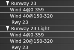
These flows are from an airport which has six flows defined for two usable and parallel runways, 05/23 and 05R/23L . The first two flows are shown here:
The first flow, “Runway 23”, declares that when the wind is at 4kts or lower from any direction or less than 40 knots from somewhere between 150 and 320 degrees, runway 23 and only runway 23 should be used. The runway is restricted to only Jets and Turboprops, which means that the airport is inaccessible for props, helicopters, heavies and fighters.
Firstly, the flow is probably incorrect, because there is also a runway 23L which will never be used at all. In fact, two additional flows exist – one for 23 and one for 23L – neither of which will ever be used because they have identical wind restrictions to “Runway 23” and come after it in the list. This particular airport is popular with GA, so disallowing props is also incorrect – but a likely explanation follows.
The next flow, “Runway 23 Light”, will never be used because there is no circumstance where it satisfies restrictions that are not also satisfied by “Runway 23”; the only difference is the wind restriction, and it is more restrictive (20kts vs 40kts). “Runway 23 Light” allows the runway to only be used by props and helicopters so even if this flow were to be used, which is impossible, it would prevent jets and turboprops from landing if the wind speed was less than 20 knots. Remember that only one flow is ever in use at any time so if no runway in the currently active flow can service your aircraft, you’re out of luck!
In general, if you have considered naming your flows after runways and you have more than one runway, the flows are probably wrong.
What would be more appropriate would be to define four flows for this airport:
W Light, covering runways 23 (a long tarmac runway) and 23L (a shorter grass runway), with “Wind 4@0-359” and “Wind 20@150-320”, with jets and turboprops assigned to runway 23 and props and helicopters assigned to 23L. Heavies should probably remain excluded; fighters are a trickier question because even a WW1 biplane could be defined as a fighter.
W Normal, covering runway 23 only, with “Wind 40@150-320”, again with jets and turboprops assigned to runway 23. This would close the airport to helicopter and small GA aircraft when the wind was above 20 knots, but leave it open for more powerful aircraft.
E Light, a copy of “W Light” but using runways 05 and 05R and with a single wind restriction for “Wind 20@320-150”. It would be pointless to include “Wind 4@0-359” because it has already been satisfied by “W Light”.
E Normal, a copy of “W Normal” using only runway 05 and the wind direction reversed to cover “Wind 20@320-150”.
Debugging Flows and Flow Changes
When the weather changes, X-Plane will wait at least one minute before beginning to change flows. When it starts to change flows, the sim goes through three phases:
Departure drain. All new departures are held, but existing departures are allowed to depart using the old flow. All arrivals continue to arrive using the old flow.
Arrival drain. Once the number of non-held departures falls to zero, all arrivals not on final are re-routed to the new flow. Existing arrivals are allowed to land on the old flow.
Complete change-over. Once the existing legacy arrivals have landed, the new flow is fully in effect and the ground hold is lifted.
Note that if the weather changes back to the old flow in phase 1, the old flow is resumed; if the weather changes back in phase 2, we continue to the new flow.
The logic behind step 1 is: we have to let all taxiing departures depart on the old runway because there might not be enough room for aircraft to turn around on the pavement. While this is happening we don’t re-route arrivals to avoid a head-on collision. The logic behind step 2 is: as long as pending arrivals are arriving in the old runway, we can’t release the gate hold because the departing aircraft might block the arrivals’ route to the gate.
By default the ATC system logs some information about flow changes to Log_ATC.txt, but you can turn on advanced and detailed logging by setting the art control atc/debug/rwy_flow to 1. Detailed logging starts after the art control is set. Log_ATC.txt can be viewed in real-time using the “developer console” menu item in the Special menu.
You can also view more details about runway selection by setting the art control atc/debug/rwy_selection to 1.
Revision History:
         2/22/23   Updated for X-Plane 11, 12
         7/ 6/16   Added data validation rules
        12/ 8/13   Clarified DSF DEM handling
         2/18/12   Updated to docuemnt 7z
         2/12/12   Updated for X-Plane 1000
         2/ 4/09   Updated for X-Plane 930
        12/26/07   Updated For X-Plane 900
         7/25/07   Initial Draft
This document outlines how the DSF file format is used by X-Plane. DSF is a container format; new features can be added to the X-Plane scenery system without changing the file format. This document lists the different legal DSF configurations that X-Plane understands.
Note: this document is a low level reference, intended for programmers who intend to create tools to edit DSF files. Authors who want to edit DSFs should simply use higher level tools like OverlayEditor, or PhotoSceneryX.
DSF Compression
Starting with X-Plane 10, X-Plane will read 7z-compressed DSF files (a single DSF compressed into a 7z archive) natively. X-Plane thus installs its DSFs without decompressing them, to save disk space. You may need to un-7z DSFs to read them. 7z compression is optional.
DSF Properties
DSF contains a series of properties, with string values. These are the properties X-Plane recognizes:
Bounding Box and Location Properties
All DSFs must contain four properties indicating the bounds of the DSF tile. These bounds are in degrees and must be integers. DSFs should contain a planet tag, which is optional, and assumed to be earth if missing.
Property Name
Default
Value
sim/north
(Required)
degrees
sim/south
(Required)
degrees
sim/east
(Required)
degrees
sim/west
(Required)
degrees
sim/planet
earth
mars
Object Density Control Properties
X-Plane only loads part of the facades and objects in a DSF, based on the “number of objects” setting in the rendering options. The “require” properties force X-Plane to load certain objects. Each require statement applies to either facades or objects, and specifies both the minimum setting where the objects are guaranteed loaded and the minimum index within the DSF of the object/facade it applies to.
More than one requirement statement can be used; all are combined together to meet all requirement constraints. Thus you can bring in objects incrementally through proper organization of the DSF object definition order.
Property Name
Value
Minimum Sim Version
sim/require_object
obj_level/first_required_index
8.0
sim/require_agp
agp_level/first_required_index
10.0
sim/require_facade
obj_level/first_required_index
8.0
Overlay and Exclusion Properties
The overlay properties control how a DSF is used as an overlay to other DSF files. The overlay property signals to X-Plane that the DSF should be loaded as an overlay and not a base mesh.
The exclude properties cause X-Plane to eliminate scenery from lower priority DSFs that are loaded underneath the overlay. Each exclusion zone is a rectangle specified in latitude and longitude. A DSF may contain multiple exclusion zones of the same type, and they may overlap.
Property Name
Value
sim/overlay
1
sim/exclude_obj
polygonal exclusion
sim/exclude_fac
polygonal exclusion
sim/exclude_for
rectangular exclusion
sim/exclude_bch
polygonal exclusion
sim/exclude_net
polygonal exclusion
sim/exclude_lin
polygonal exclusion
sim/exclude_pol
polygonal exclusion
sim/exclude_str
polygonal exclusion
sim/filter/aptid
airport ID
The quality of culling depends on the type of scenery being excluded. In some cases, culling may over-remove or under-remove scenery.
[X-PLANE 9] X-Plane 9 improves the quality of forest exclusion. While X-Plane 8 forest exclusions remove a forest polygon if any vertex is in the exclusion zone, X-Plane 9 forest exclusion zones exclude on a per-tree basis for more precise cuts.
A rectangular exclusion is four floating point coordinates lon/lat coordinates in the form of
west/south/east/north
[X-PLANE 12] A polygonal exclusion is a rectangular exclusion (for compatibility) or:
The rectangle should be a bounding box around the polygon, and the polygon should contain at least three points and no overlapping edges or holes. Concave exclusions are allowed. Like rectangular exclusions, the exclusion is a containment test with any point in the geometric primitive, so containing a single corner of an AGS will remove the entire AGS, for example.
The intent of poylgonal exclusions is to allow simple shapes to be modeled directly instead of using a large number of thin axis aligned bounding boxes. The outer AABB provides backward compatibility with X-Plane 11.
[X-PLANE 11.50] X-Plane 11.50 can exclude by airport ID – see the section on custom DSF comments for more. Each sim/filter/aptid establishes a zero-based indexing scheme to airport IDs for this purpse.
LOD Properties
[X-Plane 930:] Historically, X-Plane measures the distance of a mesh patch based on an arbitrary center point computed from the geometry. Since two different LOD mesh patches may have different vertices, their centers will be different. This cannot be predicted by authors. So for example, if a first patch has an LOD of 0 -> 20000 and the second one has 20000 -> -1, the first mesh patch may not disappear when the second one appears because they are being measured using different center points.
Setting the property sim/lod_mesh to 1 changes X-Plane’s behavior in the following way: the center point for LOD calculations of a mesh patch with a non-zero LOD start value will be taken from the previous mesh patch in the command stream.
This in turn means that a series of consecutive mesh patches with increasing LODs (starting at 0) will all have the same center point, and can be switched between using consecutive LOD values. (Also note that when this option is used, the closest LOD must come first, to establish the center point!
Other Properties
For historical reasons X-Plane will only flatten a terrain mesh if these properties are present.
Property Name
Value
sim/creation_agent
X-Plane Scenery Creator 0.9
sim/internal_revision
0
Raster Layers
X-Plane interprets multiple types of raster data in the DSF:
DEM Name
Contents
Supported In
elevation
MSL Elevation Data
X-Plane 10
sea_level
Bathymetric Depth
X-Plane 11
soundscape
Sound codes
X-Plane 12
spr1
Seasons: start of spring, day of year
X-Plane 12
spr2
Seasons: end of spring, day of year
X-Plane 12
sum1
Seasons: start of summer, day of year
X-Plane 12
sum2
Seasons: end of summer, day of year
X-Plane 12
fal1
Seasons: start of fall, day of year
X-Plane 12
fal2
Seasons: end of fall, day of year
X-Plane 12
win1
Seasons: start of winter, day of year
X-Plane 12
win2
Seasons: end of winter, day of year
X-Plane 12
Elevation Raster Data
[X-PLANE 10] Elevation should be specified via a raster DEM file. If the vertex elevation is the flag value -32768.0 then the DEM elevation is sampled. This method is recommended because X-Plane can use the elevation DEM for other purposes as well as meshing.
Bathymetric Data
[X-PLANE 11] The depth of the sea floor is specified via a bathymetric DEM; elevations are absolute MSL meters. The behavior of the depth vertex variable varies by version and data.
Sim Version
Bathymetry Present
DSF Depth Coord/Flag
X-Plane 10
No (not used)
Depth
X-Plane 11
No
Depth
X-Plane 11
Yes
0 for coastline, 1 for use bathymetry
X-Plane 12
Yes (required)
ratio for interpolation: 0 is ground elevation, 1 is bathymetry sample
Sound Raster Data
[X-PLANE 12] A sound raster file specifies codes that drive environmental sounds throughout the scenery. Codes are:
0 or invalid = barren
30 = water (we don't differentiate between water body types because we don't have the data on the DSF yet)
40 = forest
50 = rural
60 = urban low
80 = urban town
100 = urban high
120 = industrial
Airport sounds replace some of these data points based on the apt.dat data loaded at runtime.
Seasonal Data
[X-PLANE 12] X-Plane 12 supports a set of 8 seasonal raster files that define the time of year of seasons. Each of the four seasons has a start and end day; within that range, the season is selected; between the ranges (e.g. blended between end of summer and start of fall) the seasonal art is interpolated.
All eight raster layers must be present. Days are days since January 1, and seasons can “wrap aorund”, e..g winter could start on day 310 and end on day 20.
Mesh Types and Coordinate Organization
X-Plane uses .ter files to specify the way mesh patches are drawn. The coordinate organization is:
Longitude
Latitude
Elevation
Normal – X
Normal – Z
Additional Coordinates…
These .ter files may contain “border” textures–the border feature of a .ter file is only used if the overlay flag is set in the mesh patch.
Mesh normals: the normal vector is stored as the X and Z ratio of the normal vector, based on a coordinate system of Y = up and Z = north at the mesh point’s location.
Additional coordinates are ordered optionally S1, T1, then optionally S2, T2. If an odd coordinate is provided, it is treated as alpha. If an alpha is needed but not present, X-Plane generates one using seeded random numbers.
Base Texture is Projected
Composite Texture Is Projected
Border+Overlay Flag
ST1 Controls
ST2 Controls
no
no
no
base
no
no
yes
base
border
no
yes
no
base
no
yes
yes
base
border
yes
no
no
base
yes
no
yes
base
border
yes
yes
no
yes
yes
yes
border
X-Plane 8 does not use the alpha channel right now that a DSF may have.
Water Handling
A mesh layer with the name water or terrain_Water is treated as water data mesh triangles; unlike regular mesh triangles, no .ter file is provided.
Water mesh triangles have a number of properties that are unique to water.
Water meshes ignore the normal parameters and have two ST coordinate controls after them:
“Fetch ratio”, a ratio from 0.0 to 1.0 that controls the scaling of waves. Use 1.0 for open ocean and 0.0 for ponds.
Depth. This is an actual depth measurement for X-Plane 10 and earlier. In X-Plane 11 and later, if a bathymetric DEM is present, then this is a flag: 0.0 for coastline and 1.0 for in-water. See raster data handling for more info.
In X-Plane 12, if a .ter file has the WATER_COLOR_MASK directive, then it is water provided via a .ter file. In this case, four ST coordinates are expected: fetch ratio, bathymetric depth flag (this directive should always be used with raster bathymetric depth) and a pair of ST coordinates defining the UV mapping for the water texture in the .ter file.
Raster Data and Meshes
If elevation raster data is present, it will be used for the elevation of a mesh point as long as:
The patch vertex’s elevation is -32768.0 or
The patch vertex’s terrain type is water.
If elevation rater data is present, all normal vectors can be left as 0.0 – X-Plane will calculate them from raster data, for all terrain types.
(By convention v10 DSFs produced with LR’s scenery tools use explicit elevation for all water vertices and all coastal vertices, to ensure precise water elevation even near dams and to keep a water-tight seal between land and water. Interior land elevation points come from raster DEMs for data compression.)
Object Types and Coordinate Organization
Objects are placed with three or four coordinate values:
Longitude
Latitude
Heading
MSL height (optional in v10)
X-Plane 8 and 9 only allow AGL positioned objects (3 coordinates); X-Plane 10 allows for an optional 4th coordinate, interpreted as the MSL height of the object in meters. (See Special DSF Comments for AGL placement).
AG Points (X-Plane 10 only) may only have three coordinates (lon, lat, heading) and are always draped.
Polygon Types and Coordinate Organization
Only one beach .bch definition may be used per DSF. Subtypes within the beach are used to create variety.
X-Plane uses a number of graphic resource files for DSF polygons. The meaning of the coordinates varies based on the type.
File Type
Minimum Sim Version
Holes Allowed?
Parameter Meaning
Coordinates
Facade (Flat, No Wall Choice)
8.0
No
Height (meters)
Lon
Lat
Facade (Flat, With Wall Choice)
10.0
No
Height (meters)
Lon
Lat
Wall Type
Facade (Curved, No Wall Choice)
10.0
No
Height (meters)
Lon
Lat
Bezier Lon
Bezier Lat
Facade (Curved, Wall Choice)
10.0
No
Height (meters)
Lon
Lat
Wall Type
Bezier Lon
Bezier Lat
Forest
8.0 (10.0 for line and point fill, 12.0 for height/MSL control)
Yes
Density (0-255) + Fill (0=solid,256=line,512=points)
Lon
Lat
height (optional)
MSL (optional)
Beach (MSL)
8.0
No
0=chain,1=ring
Lon
Lat
Elevation
dx
dz
subtype
Beach (AGL)
10.0
No
0=chain,1=ring
Lon
Lat
subtype
Line (straight)
8.5
No
0=chain,1=ring
Lon
Lat
Line (curved)
8.5
No
0=chain,1=ring
Lon
Lat
Ctrl Lon
Ctrl Lat
String
8.5
No
Spacing (meters)
Lon
Lat
String (Curved)
8.5
No
Spacing (meters)
Lon
Lat
Ctrl Lon
Ctrl Lat
Draped Polygon (no UV)
8.5
Yes
Texture Heading
Lon
Lat
Draped Polygon (curved, no UV)
8.5
Yes
Texture Heading
Lon
Lat
Ctrl Lon
Ctrl Lat
Draped Polygon (with UV Map)
8.5
Yes
65535
Lon
Lat
S
T
Draped Polygon (curved, with UV Map)
8.5
Yes
65535
Lon
Lat
Ctrl Lon
Ctrl Lat
S
T
Ctrl S
Ctrl T
Autogen Block
10.0
No
Block Code + 256 * (Height / 4)
Lon
Lat
Autogen String
10.0
Yes
Number of Active Sides + 256 * (Height /4)
Lon
Lat
For forests, the density is a scaling factor–255 makes the maximum number of trees, 0 makes none. This control is multiplied by the rendering settings to set a final number of trees. Tree density will not exceed the maximum possible density from the .for file.
X-Plane 10 : in X-Plan 10, a packing code is added to forest density. 0 gives the default behavior of filling the polygon with trees. 256 gives the behavior of plotting trees along every line of the polygon, treating each contour as a poly-line. 512 gives the behavior of plotting a tree on each point in every contour. Note that:
Poly-lines are not auto-closed with line filling (to allow for U shapes) so you must duplicate the final point to make a ring.
In point-fill mode, all points are equal, so there is no advantage to using contour rings.
For beaches, the parameter can specify a ring, which connects the end point to the beginning. This will create a correct texture transition from the end to the beginning. The dx and dz coordinates for the beaches are a normal vector, similar to a DSF’s normal vector, and are used for draping the beach. The subtype parameter is an integral subtype which describes which beach from within the .bch file is used.
X-Plane 10 : in X-Plane 10, the normal vectors and elevation of beaches can optionally be omitted, as X-Plane derives this information on the fly.
For draped lines (.lin), object strings (.str) and draped polygons (.pol) if bezier coordinates are present, then bezier curves are generated.
For object strings, the spacing of objects is controlled by the polygon parameter. For draped lines, the polygon may be treated as a ring or chain. Like beaches, best results come from using the ring feature rather than duplicating the first point. For a draped polygon, texture coordinates (ST from 0 to 1) may also be included–the parameter value 65535 indicates this.
X-Plane 12: in X-Plane 12 for draped polygons whose parameter is not 65535 (e.g. texture projected by heading, not UV mapped) if the heading exceeds 359, then the integral heading divided by 360 is used as 128th of a degree and added to the heading modulo 360, to provide sub-degree resolution. In other words:
For both autogen blocks (.agb) and autogen points (.ags) the height of variable height elements is encoded in the upper 8 bits of the parameter (e.g. * 256) and represents the metric height divided by four. (In other words, some precision in height is lost to allow for a wider range of building height.
For autogen blocks, the lower 8 bits of the polygon represent a spelling set code – this is used to look up which “spelling set” in the autogen block to use. A typical use is to use different tile arrangements based on different block codes. X-Plane’s global scenery, for example, uses codes 0-7 to indicate whether the “back 3” walls are road adjacent or not.
Autogen strings represent the strangest polygon feature of all. Unlike other polygons, the contours in AGS are interpreted as poly-lines ( not closed polygon rigns!); the AGS is required to be a closed polygon with holes when all contours are considered.
The first N contours (where N is the lower 8 bits of the polygon parameter) will spawn autogen buildings; the rest of the contours are used only to create a closed polygon-with-holes area.
A few examples may help clarify autogen strings:
In the case of a single rectangle city block with houses on all sides, there would be one contour with 5 points (the start point must be duplicated) and the polygon parameter N=1.
In the case of a single rectangle city block where the north side has no houses, there would be two contours: the first contour would contain the NE, SE, SW, NW points and the second woul contain the NW, NE points. N=1 because only the first contour has houses.
In the case where only the east and west sides of the block have houses, there would be four contours: NE,SE then SW, NW, then NW, NE, then SE,SW. N=2. Note that the first two and last two contours can swap with each other.
In the case where a city block has houses on all sides but a lake in the middle, the first contour is the block (with a dupe point to close), the second is the lake (with a dupe point to close) and N=1.
X-PLANE 12: in X-Plane 12, a forest in point mode (and only point mode) can optionally have a third and fourth data coordinate plane; these planes are used to control tree height on a per tree basis and vertical registration if desired. There is no mode to get randomized heights with fixed MSL locations.
Road Types and Coordinate Organization
Only one road.net definition may be used per DSF. Subtypes within the road file are used to create variety.
Road network files use 4 coordinates.
Longitude
Latitude
Elevation
Junction ID
Road segments are connected via junction IDs with the following rules:
The DSF file’s junction IDs must start at 1 and contain no gaps. 0 is reserved as the “no junction” flag.
A road chain must start and end with a junction.
A junction must be used any time an intersection is desired.
A junction must be used any time a road chain changes subtype.
All nodes that share the same junction code must share the same coordinates.
A junction should not be used for nodes that are designed only to change the path of a road (“shape” points), because the processing overhead is higher for junctions.
X-Plane 10 : if the road.net specifies a draped road type then the elevation should be a stacking layer number (0 for the ground, then 1, 2, 3, etc.) for all junctions to specify overpasses. Within the chains, the shape point should be 0 for a vertex and 1 for a bezier curve control point. There must be no more than two consecutive control points in a road. (That is, quadratic and cubic bezier curves are allowed but no higher degere polynomials.) All bridge-crossing roads should use a junction so that the sim can ensure separation.
DSF Feature Extensions Via Comments
Airport-ID Based Exclusion/Filtering
Starting in X-Plane 10.45, sections of DSF overlays can be filtered by airport ID. The mechanism works as follows:
The properties table contains sim/filter/aptid properties that establish an indexing scheme to particular X-Plane airport IDs.
X-Plane determines whether a given airport ID is “owned” by the scenery pack that contains the DSF. If the airport is in the apt.dat of this pack (and not in a higher-priority pack) then the airport ID is owned.
When a filter directive sets the filter to a given index, all following network segment, polygon, and point features are excluded unless the airport is part of this pack. Filtering is done at the interpretation level; DSF command state is not skipped.
Filter commands are encoded via a DSF comment with the following format six-byte format:
uint16 comment type - must be 1
sint32 airport index - can be -1 to clear the filter or [0...properties)
Like all DSF command table data, these ints are little endian. Filter state is considered to be “off” by default.
The intent of this feature is to allow a DSF to place objects that are “part” of an airport and will be removed if a higher priority pack replaces the airport, even if the higher priority pack does not correctly provide exclusion zones.
AGL-Offset OBJ Placement
Starting in X-Plane 11.50, explicit-height OBJs could have their datum changed from MSL to AGL. The format of the comment is:
uint16 comment type - must be 2
sint32 AGL mode - 0 for MSL, 1 for AGL
The flag affects all point placements for OBJs until the mode is further changed; the default mode is MSL.
Overlay DSF Restrictions
DSF overlays have restrictions on the types of files they may use:
[X-Plane 8:] Road networks are not allowed in overlays.
Mesh patches are not allowed in overlays.
X-Plane 9 relaxes the road network rule–in X-Plane 9 a DSF overlay may contain a road network, but the one-.net-per-DSF rule still holds. When a DSF overlay has a road network and the base mesh does too, the junction IDs between the two do not connect.
Guidelines for DSF Extension
Consider all properties starting with “sim/” as reserved.
Do not add extra coordinates to vertices beyond what is in this spec.
Data Validation
These rules place limits on the kinds of data that can be specified for various art assets.
Base Mesh
Every point within the lat-lon rectangular boundaries of the DSF must be covered by exactly one triangle that is ‘hard’ (meaning the hard flag in its parent patch is set).
It is illegal for a triangle’s vertex to be located on the edge of another triangle; triangles must only meet vertex-to-vertex, not vertex-to-edge. (In other words, there can be no “T” junctions in the mesh.) Triangles meet at vertices if the coordinates of their vertices have the exact same lat, lon and elevation bit-values.
Objects/AGPs
Objects must be within the DSF lat/lon boundaries.
Object heading should be between [0 and 360).
Polygons
Area rules (these apply to facades with roofs, draped polygons, filled forests, AGS and AGB).
All polygons must have counter-clockwise winding for exteriors and clockwise winding for holes.
Polygons must not be self-intersecting.
Line rules (these apply to all polygons except for forests in “points” mode).
Polygons must not have zero length sides.
Roads
All roads chains must be made of at least one segment.
All road segments must have positive length.
It is illegal for a road segment to reverse direction (E.g. have a 180 degree turn).
A junction must not have two roads entering the junction at the same heading and the same level.
No more than two shape points within a chain can be bezier control points. (In other words, a cubic bezier is the highest degree bezier supported in curved roads.)
While a bezier control point may be outside the DSF boundaries (typically the point pools contain some margin to allow this) the actual path of the road segment must remain within the DSF boundaries.
While it is not necessary, it is recommended that crossing roads share a junction at the crossing point with the roads on different levels; X-Plane can use this information to try to ensure that the roads are not reordered vertically due to the road draping and smoothing process.