Over time, certain patterns appear in bug reports, questions and occasional flat-out strops about the ATC system and how it works. While I’m making no attempt to say that it’s perfect – trust me, I know very well it’s not – a lot of the things that come up regularly are easily explained and, in most cases, down to misunderstanding or misinterpretation. This article, which I expect to grow over time, will cover the most common points.
Basic Misconceptions
ATC is not route guidance
If you’re used to hearing a GPS in a car issuing turn directions you might easily think that ATC is basically a three-dimensional version of that; it just gives headings and altitudes to move you along whatever route you have in your FMS and if you take a shortcut or change your mind, it will just recalculate and give you the next best route. This is not true. ATC is a safety service, not a route guidance service. To be flying in the first place, it’s assumed that you’re competent to follow a route yourself. ATC guidance comes in only when the route is insufficient, or you’re in a busy environment and safety concerns are more relevant than waypoints.
You can’t just disregard an ATC instruction because you think you know better, or you simply want to do something else. ATC has the overview of what’s happening in the entire region around you and requires that you follow their guidance to keep everybody safe.
Your FMS is irrelevant to ATC
The controller you’re talking to neither knows nor cares what your FMS is telling your autopilot to do. The unspoken contract is that the controller will keep you safe provided you follow their instructions. The FMS is there to assist you to follow those instructions and nothing more. If the route in the FMS doesn’t match what you filed, or what ATC is telling you needs to be done, reprogram your FMS.
Why does ATC keep telling me to “descend and maintain 10,000 feet” when I’m already there?
Incorrect altimeter setting
Possibly the most common thing reported as a bug, being told to “descend and maintain 10,000 feet” or similar while the aircraft appears level at 10,000 ft is down to your altimeter setting. If you’ve left it set to 1013 (or 2992 in the USA – different units) when you descended through the transition altitude, the altitude that your altimeter shows will be different to the one the ATC controller sees you at. If in any doubt, use the “Request Altimeter” radio call.
The same principle applies if your altimeter is set to anything except ISA above the transition altitude. Also, always check what the transition altitude and layer actually are in your location – especially for Americans, remember that the rest of the world does not have these set at a uniform 18,000ft.
Finally, always use the pressure setting given by the controller you’re talking to! No other source – for example your destination airport, pressure at the aircraft’s exact location or an online source – will give you the correct value.
Misinterpreted instruction
The other variant of this is when the actual command is misquoted. Originally it was “descend and maintain FL100”, not “descend and maintain 10,000 feet”. These are not the same thing! Any altitude given as a flight level tells you that the pressure setting must be ISA, while any altitude given as feet tells you that the pressure setting must be whatever “altimeter”, “QNH” or “QFE” the controller stated.
Obviously for both of these, the same applies for any altitude-related command, and for any altitude, not just 10,000 feet.
Why does ATC stop issuing climb or descent instructions during IFR flights?
Misunderstanding of what procedures (SID/STAR) really are
Many people believe ATC has stopped working because no further climb or descent instructions are given after departure or before arrival. If you are using a procedure – a SID, STAR or APPCH – these often contain restrictions on both speed and altitude, and even the direction in which to make a turn; they are not simple lists of waypoints. You are expected to obey all restrictions without spoken guidance, that’s the point of having published procedures, so the controller will not transmit per-turn instructions unless you stray from the published route – including the restrictions.
Not listening to the controller’s instructions
Pay attention to prior messages! You may get more than one action in the same message, including future actions, such as “Climb now to 13,000 feet then climb pilot’s discretion to FL340”. You won’t get a second instruction to climb to cruise altitude after you reach 13,000ft or when the SID ends, that clearance has just been given to you.
Why does ATC not confirm the SID or STAR I filed in my flightplan?
It seems that there is a widely-believed misconception that the “Issue Procedures as Vectors” checkbox in the flightplan dialog is just a way of having the controllers read out your turns for you instead of staying silent. This is not true. If you use that checkbox, or make the “No Procedures” radio call, or use “NO SID” or “NO STAR” as part of your filed route, you are telling the controller that you or your aircraft are incapable of following a procedure. If you do this, you should not hear any procedure name mentioned at all for the entirety of the flight.
This does mean, though, that if you don’t get assigned the procedure you expected, even if you filed one, you are not going to hear the name of the procedure you did get assigned. (The controller is free to use a published procedure for your route, they just won’t ask you to fly it autonomously). This is intentional! By stating that you are incapable of flying procedures, you have committed to following per-turn instructions which means that it will be impossible to preset your FMS with a particular route. It’s up to you to make the turns, altitude changes and speed changes exactly as the controller states, exactly when the controller states, without knowing what procedure if any they belong to.
ATC gave me crazy turns as soon as I started flying the STAR!
You’ve set your FMS incorrectly after declaring inability to fly procedures
If you’ve told the controller that you’re unable to fly procedures then any procedure you programmed into your FMS, whether for departure or arrival, is instantly and automatically wrong except by blind luck.
You’ve set your FMS incorrectly for the granted clearance
Another variant of this is simply that you weren’t assigned the STAR or other procedure that you requested in your plan. Your plan is a request, not a command, and if operational reasons mean that a procedure you requested is not currently usable you’ll be assigned an alternative. Listen to the controller’s response to your clearance request when filing the plan, and when you hear “Expect <procedure> arrival” or “Descend via <procedure>” as you approach your destination. Always use that as a trigger to check that the procedure you’ve been allocated is the one programmed into your FMS.
I ended up almost overhead the airport at 13,000 feet!
Just because you’re headed straight for a runway doesn’t mean you’re going to land on that runway. Many airports have procedures that take you directly overhead the airport at altitude and then descend on the far side while executing a procedure turn to put you back on the glideslope for the other end of the same runway.
As with “crazy turns”, always check that the runway stated in the “Expect…” and “Descend via…” or approach clearance calls matches the one you set in your FMS, and the one you try to land on.
Why does ATC tell me to climb near the airport while on approach?
Closely related to the previous question, this happens if you’ve descended below the commanded or cleared altitude. Remember, that altitude may be an unspoken restriction in the published procedure and it’s up to you to check and obey these! Especially if you’ve seen a runway dead ahead and descended sharply to land on it, check that you’ve not descended below the cleared altitude and that you’re not trying to land on the wrong end of the right runway.
Why did ATC tell me to descend to a crazy low altitude for the whole length of the STAR?
There is a difference in phrasing in different parts of the world. In some locations you will be told e.g. “Descend via <STAR> to 5,000ft”. This is saying that the final cleared altitude is 5,000ft, not that you must descend immediately to 5,000ft and then stay at that altitude for the next 70 miles. You should obey all altitude restrictions published as part of the procedure, exactly as in any other case.
What’s this “Descend via <STAR> except maintain 12,000ft until <WAYPOINT>”?
Yet another version of “procedures contain altitude and speed restrictions”, this tells you that you should maintain the stated altitude until a certain waypoint, after which you should obey the published restrictions without further instructions. This will be used in the case where you’re already below some of the higher restrictions. There’s a very similar version for climbing out on a SID where your final cruise altitude is below some of the higher restrictions.
Why did ATC tell me to climb on a SID and then immediately descend to 4,000 feet afterwards?
Check your flightplan both before and after filing it! If you’ve used a very low cruise altitude, often done by people typing e.g. “360” intending “flight level 360” but actually meaning “360 feet”, ATC will round up to the minimum safe altitude for the route. You will be told this when the controller reads you your clearance, and you will read it back to the controller. This situation comes about when you have a mistakenly low cruise altitude and a SID with no conflicting altitude restrictions.
If there are any differences between what you requested in your plan and what’s actually issued, they will be listed in the controller’s spoken clearance with the word “except”. If you do make this mistake, remember that you can request cruise altitude changes. It might take a few steps because the options available here are restricted to keep menu sizes reasonable.
Why does ATC think I’m off course when I’m not?
The route in your FMS doesn’t match the route you were cleared for
A common cause of this is that the route you filed is not the route you programmed into your FMS. You may have missed a waypoint either in the plan or in the FMS, or you may have altered the route in your FMS after filing the plan.
The rule is that if you file it, you fly it. That said, you can often recover from this situation if you request “Direct to navaid”, where each navaid on your filed route will be given as a choice or, of course, entering the missing waypoint into your FMS.
Also see above, the “crazy vectors on arrival” questions.
Your autopilot isn’t turning fast enough
If you’re getting vectors for departure or approach, and you’re flying on autopilot, check the turn rate limiter if your aircraft has one. Slow, gradual turns at low rates are fine for cruise but during this stage of the flight when you’re told to turn you need to turn immediately, and potentially sharply. Remember, STARs are published rather than invented by the sim and will frequently contain tight consecutive turns which require a high bank angle.
Why does ATC not just use my FMS? That’s the route I wanted!
How does a person sitting in a room hundreds of miles away see a six-inch screen in your cockpit at 38,000 feet? You request a particular route in your plan; ATC will monitor you along that route, and exactly that route, and give guidance where necessary; you respond to that guidance by programming your FMS to reduce your workload. The FMS is the last step in the chain of command, not the first.
Children of the Magenta Line consider this to be heresy.
Why does ATC never tell me to descend?
You’ve been mis-using the cruise altitude change
If you’re using repeated “Request Altitude Change” requests to perform a descent to your destination, you’ve missed the “Request Descent” call. The first is for changing your cruise altitude, not performing a manual step descent.
As you approach your destination you will have the option to “Request Descent”, to initiate the descent phase of the flight. If you leave this late, the controller will eventually prompt you to start descending. By continually requesting lower cruise altitudes what you’re actually doing is pushing that controller-initiated descent instruction further and further forward to the point where you can end up at a few thousand feet close to the airport without the actual descent phase starting.
Your route isn’t what you think it is
If you don’t see the “Request Descent” call as an option then re-check the route you filed – this will always be available in the ATC dialog’s transcript. In one case, someone accidentally filed a navaid nearly 1,800 miles beyond their destination as an intermediate waypoint so even directly overhead the airport, they still hadn’t had the descent instruction. Of course they hadn’t – they still had 3,600 miles to fly before they needed to descend!
Why do I fly directly overhead the airport before getting the descent instruction and get vectors taking me away from the airport again?
As in the previous question, if you file it, you fly it. Don’t file any waypoint closer than the initial fix for the STAR you wish to use. If you file the airport name itself, or a navaid on the airport, as part of your route you’ll be expected to fly to that navaid and only then enter the approach and landing phase. Especially if you’re very close to the airport, you’ll almost certainly be directed away from it to a point where you can join a procedure or a standard pattern approach.
Why did ATC give me turns taking me away from the runway?
This is not the runway you’re looking for
The most common reason for this is that you’re landing on the wrong runway. Remember to check the runway that’s specified in the “Expect…” and “Descend via…” calls – it may not be the one you intended. It may well not be the one closest to you, or the one that an online flight-monitoring website says is in use, or even the one that’s best aligned for the wind. You may be expected to land on the other end of a runway dead ahead of you – as above, just because you’re headed for it doesn’t mean that’s the runway you’re landing on.
You’re too close to the airport
The other possibility tends to come after a manual (and incorrect) step descent using repeated “Request Altitude Change” commands. If you end up too close to the airport you may well be repositioned further away before getting final approach vectors. The same will happen if you’ve ignored previous turn instructions and headed straight for the airport.
How do I know which runway to select when ATC only gives me a SID during clearance?
When you file your flightplan before departure, it’s reasonable to expect to be given the departure runway. The delay here is that some time may pass between filing the plan and executing it – pre-flight checks, loading etc. – in which time the active runway may change, or a different runway in the active set may become a better one to use. You’ll be given the actual departure runway when you request taxi. In the meantime you can find out what the actives are using ATIS.
Tumpty-tumpty-so I just ignored that and turned/descended
Wrooooooooong! If you’re being given vectors or any other explicit instruction, you need to follow that instruction. You also need to not make turns or altitude changes without explicit instructions when you’re under ATC control (except for flight following of course). It’s ATC’s responsibility to keep you and everyone around you both in the air and on the ground safe and that’s not possible in a busy, near-airport environment if every aircraft just makes it up as they see fit.
ATC will never ask you to do something that looks outside the capabilities of your aircraft, or which would be dangerous. If it does, that’s a clear bug and needs to be reported so it can be prevented. If you don’t understand why you got a particular instruction, or why you didn’t get one you were expecting, review the message transcript because 99 times out of 100 this shows a disconnect in understanding rather than an error in the controller’s decision-making.
If you go off-piste then the controller will diligently – and tirelessly – try to get you back on track. This may well involve repositioning you further away from the airport if you get too close. If you’re simply beelining for the brightest set of PAPI lights, the closest runway to your heading or a runway that’s set in your FMS even though it’s not the one you were told to land on, they’re not going to just throw up their hands and say “Oh, go on then”.
Why does the “Get from FMS” option not work?
Not all third-party aircraft, notably those with custom avionics, support any kind of interaction with the simulator’s default systems. Even though they would be able to read and write to the default avionics and transfer the routes to and from their own custom versions, this is just not done. X-Plane makes the information about routes available but can not force third-party developers to use this information.
Why didn’t the approach controller clear me for approach?
Depending on the airport’s level of control, you may need to call the airport directly rather than have a regional or approach controller clear you and hand you over. Outside the US this is common for smaller fields – typically but not exclusively GA-focussed airports. Even if you’ve filed a plan, you will be taken very close to the airport and then told to contact them directly to request landing.
I can’t make any radio calls except “Uncertain of Position” and “Radio Check”
You’ve left a controller’s frequency with outstanding readback. Obviously in real life this doesn’t prevent you from making new calls to a different controller but it’s bad practice. The sim indicates this by making you go back and complete your readback before allowing you to check in with the new controller.
Another possibility is that you departed from a FISO airfield and didn’t tell them you were leaving their frequency. This is also bad practice.
Flight Following: I didn’t get handed off properly
When you’re getting flight following, services from ATC are generally provided at their discretion. If they’re too busy, or in a part of the world where coordinated handoffs are less likely, you may not get a coordinated handoff when you fly into another controller’s airspace. In that case, it’s up to you to re-request flight following from the new controller.
Flight Following: I’m not getting turn instructions
Flight following is not the same as following a flight plan! This is a service targeted at unplanned flights, generally GA flights, where the pilot wants to be in contact with a controller for safety and coordination but is free to fly as they wish provided they obey basic rules.
This is not a way of avoiding getting strict vector instructions on landing! At a controlled airport you will still be given vectors and will still be expected to follow them precisely.
Flight Following: I didn’t get handed off after departure
As with many things in flight following, the pilot must use their own initiative at certain times. If you depart a FISO airfield they will not hand you off as you approach the edge of their airspace or ATZ. It’s up to you to tell them you’re leaving their frequency before switching to a new frequency to request flight following.
I can’t contact my destination and I’m only 80 miles away
Check that your destination actually has a person you can speak to, either fully-controlled or a FISO. If they only have UNICOM/CTAF, that’s not yet handled by X-Plane and the frequency will be empty. For smaller airports, and especially small FISO airfields, you may simply be outside their transmitter range. This also takes account of terrain so if line-of-sight from you to the airport is broken the effective transmitter range will be reduced. Finally, the airport may simply be closed (i.e. out of working hours, not temporarily closed due to unflyable conditions) and there is simply nobody there to answer your call.
It’s a very common misconception that it’s possible to read the latest METAR file for real weather and then expect to see X-Plane report exactly those numbers in ATIS and other weather reporting tools.
This is completely wrong.
The sim’s weather is made up of many more datasources than a single METAR entry. Some of those are downloaded data, some are determined by the sim’s code which is under near-continual revision. There is a certain amount of randomness involved too. Looking at a single METAR is maybe 10% of the puzzle, and often much less than that.
How the weather data is blended
The weather is always in transition between two states; one “before”, one “after”. When it reaches the “after” state, “after” becomes “before” and a new “after” state, already prepared and waiting, is used. Each state is made up from forecast data (GRIB), past data (METAR), and in many places it’s affected by varying levels of randomness.
Very briefly, the background weather for the world is populated from the GRIB – forecast – data. This gives fairly coarse coverage, but it is a global dataset. After that, point weather samples such as METARs are overlaid. As the distance from the sample point – for a METAR, typically the airport’s center – increases, it has a decreasing effect until it eventually gets to the point where it has no effect whatsoever. This is one place where a small amount of randomness is used, to prevent these point data sources from appearing as neat cylinders of different conditions.
The strength of a point source is also reduced in line with its age. If a METAR is only a few minutes old, it will have maximum effect. As it gets older, it has decreasing effect until eventually it has no effect at all. Would you expect to read a weather report from six hours ago and go outside to find an exact, to-the-digit match for temperature, dewpoint, wind speed and direction etc.? Of course not.
> 💡 METARs are inherently outdated. They do not represent “what the weather is now”. They represent “what the weather was at some point in the past”.
Finally, we need to consider other point sources nearby. It’s very common to find airports close enough to each other for their METARs to overlap, even in some cases right at the airport’s centerpoint. Where two or more point sources overlap their blend becomes much more complicated because, for any given point near those airports, the resulting blend will be based on each source’s location, age, type (AUTO reports have a smaller radius of effect), and the random noise applied to each one.
How the weather data is sampled
To determine what the weather conditions are at any given time at any given point on the Earth, we need two states; one before, one after. The current time determines the proportions of each state, and a third final state is generated based on that proportion and the exact location of the sample. Only now is it possible to say “the visibility right here, right now, is X miles”.
Trivial Case
In the very simplest case for real weather, we would have a single isolated airport and the sample point would be on that airport. The center of each point reading is prioritised for some distance so in theory, the METAR would be applied at full strength for far enough out to give consistent results for even the largest airports. Therefore, the numbers reported in the sim should exactly match the latest METAR, right?
Wrong. Remember there are two states in time, and the resulting conditions will be somewhere between the two. If the previous METAR had different conditions, the result will not be exactly what the current METAR states.
In the even simpler (and unlikely) case where both the previous and current METARs have the same numbers, now we should be seeing those exact numbers, right?
Wrong. Or, at least, probably wrong. The age of the METAR is taken into account when it’s being blended over the background GRIB data. If one or both of the METARs are old then they will have less effect even at the center, so the background data will start to become more visible; the numbers you get will be partly from the METAR and partly from the forecast. If both METARs are so old as to be useless, even though they’re the latest in the downloaded files and you’re right in the middle of the airport, they will have no effect whatsoever.
> 💡 It is not possible, even in the simplest possible case, to determine what the exact weather conditions will be by reading a single METAR.
Trivial Case, off-airport
Continuing from the previous example, but sampling off-airport, the situation is more complex. Outside the central region around its location, a METAR’s effects fade away over a certain distance in a semi-random manner. This randomness is different for each airport, and for each launch of the sim (apart from special testing scenarios). If you sample the conditions inside this blend zone, the exact results will change with all the previous things (time, age of both past and current METARs) plus your exact location. If you sample 100 meters away, the noise pattern will be different and the background (GRIB) weather reading that’s being blended with will be different; this is also smoothed and blended in a semi-random way otherwise there would be harsh straight edges between 1 degree or 1/4 degree boundaries.
Complex, realistic case
For many major airports, these trivial scenarios are not relevant because there will be other airports close enough that their respective areas of influence overlap. In this situation, each airport will have two different METARs with two different ages. Each will have a different noise pattern affecting how strongly it should be applied to the background weather, and relative to each other nearby airport. Each may have a different radius of effect. The exact blend pattern resulting from these overlaps is highly variable and the code for producing these changes regularly. Even though we try to keep the areas close to the METAR’s center being blended at full strength, “full strength” may be almost nothing – or nothing at all – for an old METAR.
> 💡 Even at the center of an airport with an old, AUTO reading it is perfectly possible, and intentional, for an up-to-date non-AUTO reading from a nearby airport to affect the resulting conditions.
What do I really need to say that the sim’s weather at a given point is a bug?
To work out exactly what the weather conditions are likely to be for a given point, you need all the following information:
The “before” METAR for this airport (for the conditions)
The “after” METAR for this airport (for the conditions)
Whether the METARs are AUTO or manual readings (to give the radius of effect)
The exact current time (to work out how old the before and after METARs are, and therefore their maximum level of effect)
All of the above information for all airports within around 20 miles
The “before” background GRIB data for this airport, which will be a blend of nearby GRIB samples
The “after” background GRIB data for this airport, which will be a blend of nearby GRIB samples
The exact current time again (to work out what proportions of the before and after states are in use)
Only after evaluating all of this information to work out how strongly each METAR will affect the conditions at your exact location, taking into account their types, ages, distances and relative positions, and then applying that mix to the much simpler background weather conditions, is it possible to say whether a specific weather value at a specific point is broadly correct or not.
I still think it’s a bug!
Okay. The next step is to file a bug with a weather dump. This gives us a way to reproduce the exact conditions, including all data and randomness, and evaluate precisely what the conditions should be at any given point.
There are several places in X-Plane where information about weather are available. This tech note describes each of them and how they relate to each other. Different sources are highly likely to return different information, by design. Weather conditions at any given point will be different to the weather at any other point, in both location and time.
The Weather Configuration
While this is not really a source of weather information, it does have an impact on the weather. When set to 'static weather' mode, very specific conditions may be set. These conditions are applied when you start your flight as a starting point. The simulator's weather system will then, from this starting point, add more details specifically including a small amount of randomness which changes across both time and distance from your starting airport. Any weather information found from any of the simulator's other systems should be expected to be similar to, but not an exact match for, static weather.
The Map Window
It is possible to use the map to get basic weather information about an airport, by clicking on the airport's icon to show the 'Airport Details' popout. On the 'Details' tab, an item labelled "Conditions", or "Current Conditions" in 12.1.0b5 and higher, shows the weather at the clicked airport at the exact time the popout was opened. The displayed information does not change after the popout has opened, so will become stale. Although the text given is similar to an ATIS message, it is not ATIS; it has no rounding, corrections or unit adjustment applied.
ATIS Transmissions
Many airports will offer an ATIS radio service. This is accessed using your aircraft's radio. The conditions given are those that were present at the time and location of recording of the ATIS message, and that recording will have a validity of either 30 or 60 minutes. Therefore, you should expect ATIS messages to differ from current conditions to some extent especially towards the end of their validity period. If conditions change significantly, a 'special ATIS' message will be issued and the ATIS identifier will be changed. ATIS frequencies are listed in the ATC dialog and on the map.
AWOS Transmissions
Similar to ATIS, AWOS messages differ in that they are fully automated messages based on conditions at the time and location of transmission. They are differentiated from ATIS messages by the absence of an ATIS identifier, and the prefix "AUTOMATED WEATHER OBSERVATION".
The simulator provides AWOS services for untowered airports and ATIS for towered airports, where the airport is defined as having an automated weather service. Both ATIS and AWOS services have rounding applied to wind direction and will use local temperature- and elevation-corrected pressure units, and regional units and phrasing.
"Request Departure Information" ATC call
At airports with a tower but no ATIS service, you can request departure information from ATC before you request taxi. This provides the weather conditions at the exact time of the radio response, at the airport's reference point.
"Request Weather" ATC call
While you are in contact with any controller that is based at a specific airport, including regional controllers, you may request current weather at their location. This provides the weather conditions at the exact time of the radio response, at the airport's reference point.
"Request Weather At…" ATC call
While you are flying a planned (IFR) route under ATC control, or if you are receiving flight following and have programmed named waypoints into your FMS, you may request weather conditions along your route from most ATC controllers. This provides the weather conditions at the location of the navaid, at the exact time of the radio response.
Pressure in some ATC messages
Many ATC responses from controllers will include QNH settings. For airport-type controllers (clearance, ground and tower), this pressure will be valid at the time of the call at the exact location of the airport. For regional or tracon/approach controllers, the pressure given will be the single pressure value used for the controller's entire airspace. Currently airspace segments are not simulated. A regional controller, especially a large one, is likely to give you a different QNH value to the one given by an airport.
"/sim/weather/aircraft/" Datarefs
These provide an instantaneous readout of the exact conditions at your aircraft's location.
"/sim/weather/region/" Datarefs
These provide an instantaneous readout of the base conditions for the region surrounding your aircraft; at the time of writing this is approximately one square degree. These conditions will not match conditions at any specific point within that region, since the weather at any given point is also based upon local information where possible (i.e. METAR data), and is further affected by the weather simulation's inherent random variation.
METAR files
These are snapshots of the current weather at an airport at a particular time in the past, used as a data source by X-Plane's 'Real Weather' mode. While many are updated hourly or more, others may not be updated for significant periods of time. They are inherently data reflecting a time in the past.
To produce X-Plane's weather in 'Real Weather' mode, these are blended with another datasource which is based on a forecast of regional weather in the near future. This blending of point samples from the past with a generalised regional forecast for the future, plus the small amount of randomness layered onto the results, means that the simulator's weather should be similar to actual conditions but will rarely if ever be an exact match with any other source of weather information.
External Websites
External sources should never be used for obtaining weather conditions in the simulator, even when flying in 'Real Weather' mode. They are highly unlikely to match due to the random elements to X-Plane's weather simulation, different data sources, and differences in the way that the various data-sources are processed.
The following is a download link for the sources for the Laminar Research default Boeing 737-800 sound bank. The project requires FMOD Studio 2.02.19 or greater. You can download FMOD Studio from the FMOD site.
You can use this project to learn how the sound for the 737 was created and experiment using the Live Reload feature. As the License below explains, you can only use it for learning purposes and you may not redistribute any part of it.
License
LICENSE AGREEMENT: B737 FMOD PROJECT AND SOURCE AUDIO CONTENT

This B737 FMOD Project and Source Audio Content License Agreement
(the "Agreement") is a legal agreement between you and Laminar Research.
By downloading, viewing, and in any way using this B737 FMOD project file
(the "PROJECT"), you agree to be bound by the terms of this Agreement.
If you do not agree with this Agreement, do not use this PROJECT.
All rights not expressly granted to you here are reserved by Laminar
Research. Upon acceptance of this Agreement, Laminar Research grants a license
to you to use this PROJECT expressly for educational or personal purposes only.
This license is granted worldwide and in perpetuity.

This Agreement includes license terms for:

a) The PROJECT, and any .bank files built thereof (altogether, the "FMOD
CONTENT"), and

b) The included .wav sound files (altogether, the "SOURCE AUDIO").

GRANT OF LICENSE:

1. FMOD CONTENT:

    You may modify, remix, redesign, and build upon the FMOD CONTENT.

    You may NOT share the FMOD CONTENT, original or otherwise modified.

    You may NOT broadcast video of the FMOD CONTENT, original or otherwise
    modified.

    You may NOT use the FMOD CONTENT for commercial or non-commercial purposes.

    You may NOT share, copy, or otherwise redistribute the FMOD CONTENT
    or any part of it.

2. SOURCE AUDIO:

    All SOURCE AUDIO is owned by Laminar Research.

    You may NOT share, copy, or otherwise redistribute the SOURCE AUDIO.

    You may NOT use the SOURCE AUDIO for any commercial or non-commercial
    purposes.

    You may modify, remix, redesign, and build upon the SOURCE AUDIO, provided
    it is strictly for PERSONAL use.


If you have any questions about this Agreement, please contact Daniela
Rodríguez Careri at <daniela@x-plane.com>.
Starting X-Plane 12.00 you can customize the airport ground vehicles. Since those are part of the APT.dat defined scenery, they are loaded early and separately from DSF scenery, and cannot be replaced via a EXPORT override on the library.txt like other library objects.
This feature allows you to make vehicles that you can include either locally in a custom scenery or as a part of a library to use in one or many of your airports. Bear in mind, though, that the custom vehicles have to be placed manually at each parking location. There’s no global replacement.
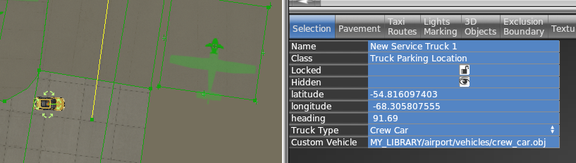
Each “Service vehicle parking location” in WED now has a “Custom vehicle” field where you specify your replacement object. The object itself will be moved around at the same speeds as the selected service truck, for the same purpose (crew car, GPU, fuel truck etc), i.e. the behavior itself is not customizable.
All components of the object (sounds, driver object etc) can be customized by the library author by providing suitably named components to go along with the vehicle object.
How to
Create your vehicle 3D model with animations. The datarefs available for animations and sound are those under sim/graphics/animation/ground_traffic/ (see the Dataref list)
On the SND file (see SND file specification) use start/end conditions according to the datarefs mentioned above. You can also use those datarefs as parameters inside FMOD Studio to modulate the events.
Ensure the events are assigned to the Master Bank androuted to the Exterior Processed > Environment bus.
If you need to apply signal processing (reverb, EQ, etc) to the sounds, don’t apply them to the Environment bus itself because they will be overriden by the corresponding aircraft bus processing. Instead, create a subgroup under Environment to do so.
Expose the object on the scenery or library library.txt (see library.txt specification) so WED can use it, via a EXPORT directive. For example
In WED, place a parking location of the kind of vehicle you want to replace (fuel truck, catering, etc) and under the “Custom vehicle” field, enter the virtual path to your custom vehicle from your library. For example
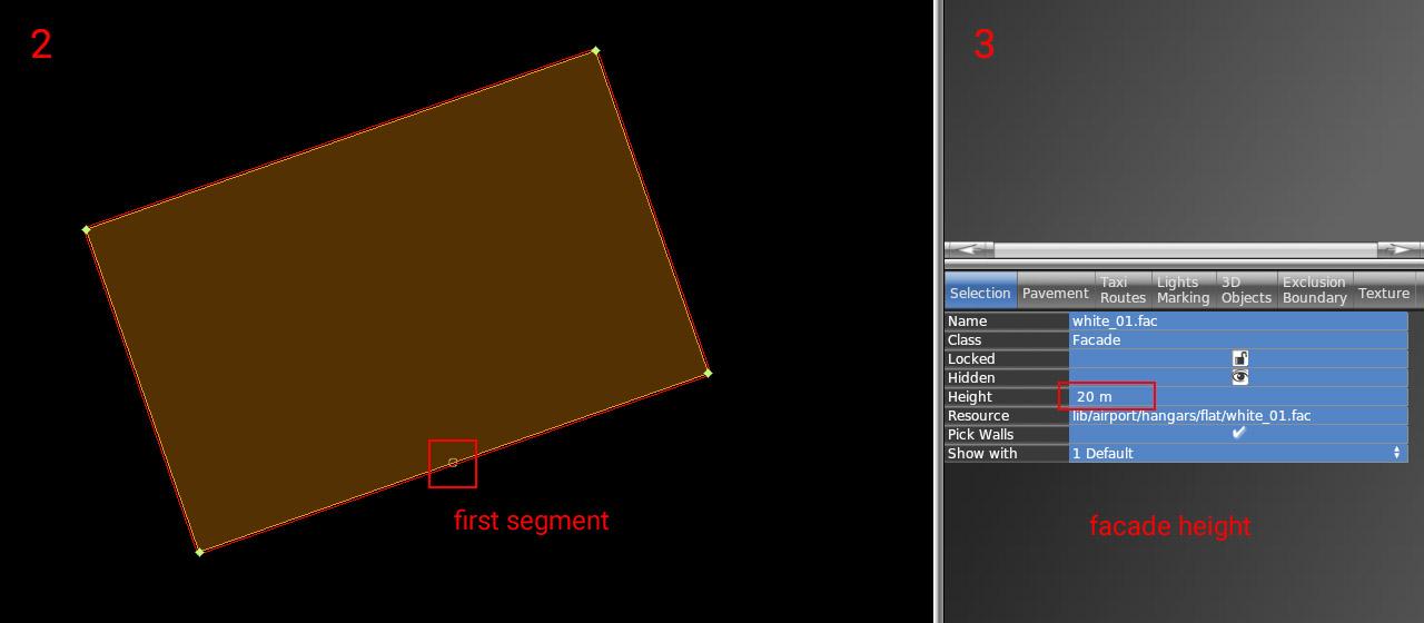
1 – As a first step, you need to put down an exterior facade. You can use any of the facades from lib/airport/hangars/flat/xxx.fac. Make sure the shape is orthogonal (CTRL + Q).
2 – Rotate the polygon (CTRL + R) until you get the first segment (marked with a small circle) to the place where the open doors should be. This is very important for future steps (aligning interior facade and doors)
3 – Set the desired height of the hangar (8, 10, 12, 16, 18, 22, 26, or 30). This is very important because the exact dimensions of openings and related parts may vary based on facade height.
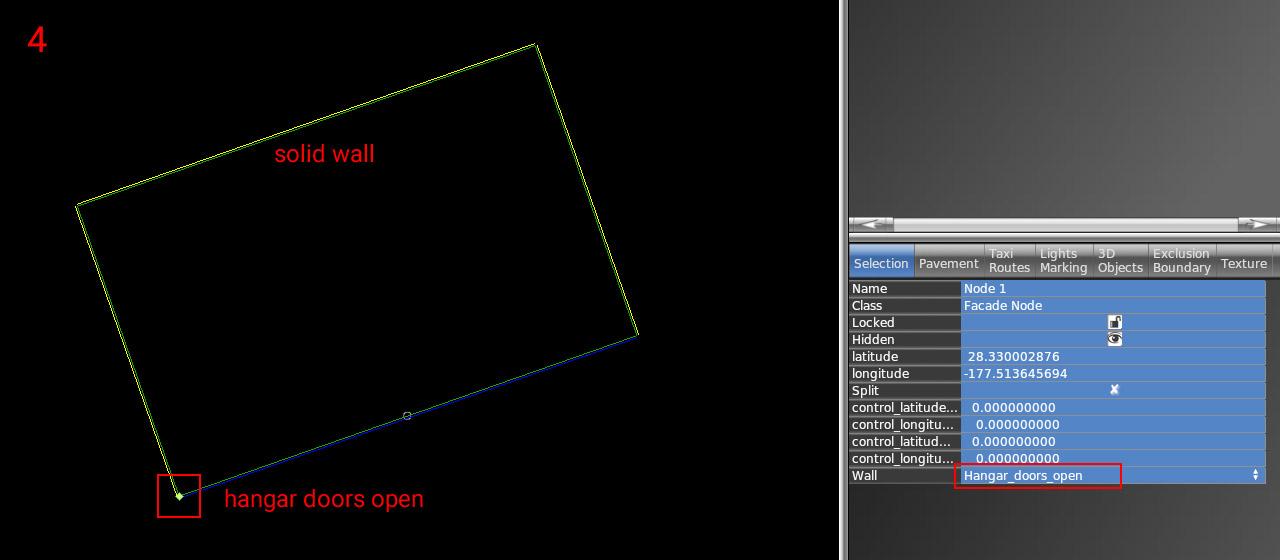
4 – Now set the correct wall types inside vertices. The most important is of course open doors (blue segment). For others, you can use whatever you need (solid walls, windows, etc).
5 – The exterior part is finished. Lock the shape to prevent unwanted edits (turn on the lock icon).
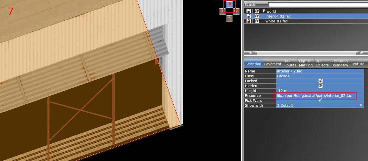
6 – Draw the hangar interior (lib/airport/hangars/flat/parts/interior_xx.fac) following the exact shape of the exterior. Use "snap to vertices" function. You should not break the exterior shape because it is locked.
7 – Make sure WED preview is turned on (menu View / Toggle Preview). Zoom to the hangar corner and use an appropriate isometric view.
8 – Set the corresponding height of the interior (7, 9, 11, 15, 17, 21, or 29). Note the height is one meter shorter than the exterior.
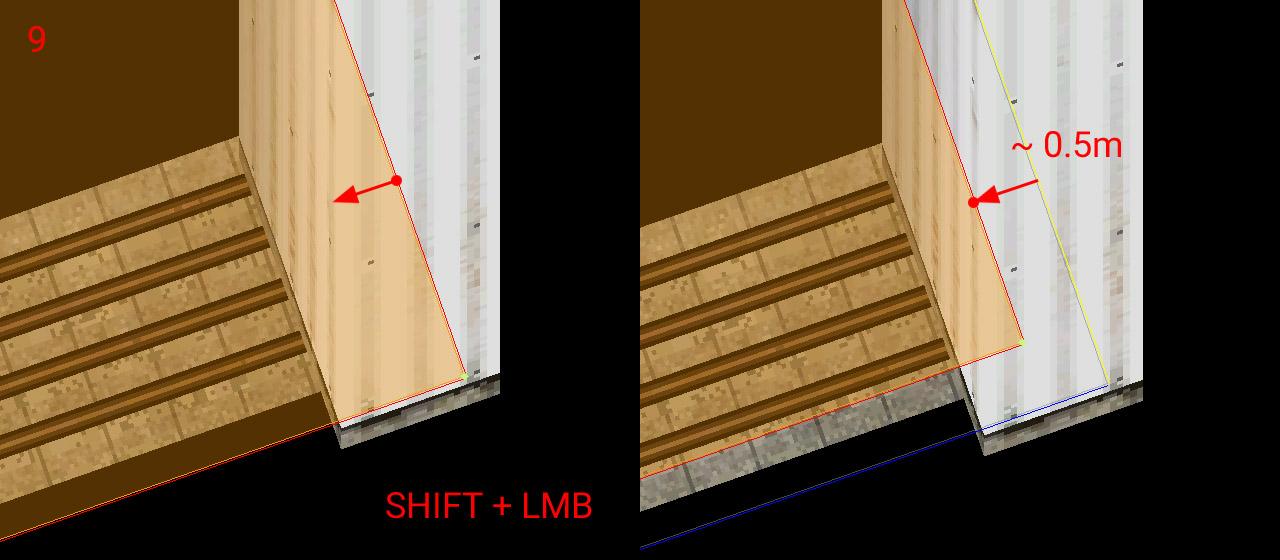
9 – With SHIFT pressed, drag the polygon toward the inside roughly 0.5 meters.
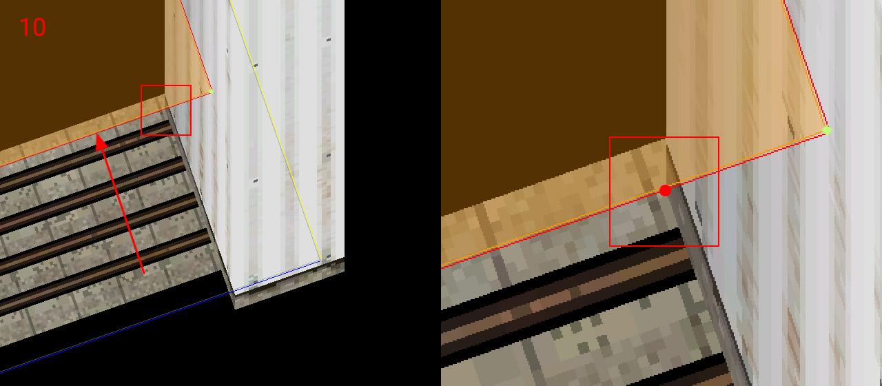
10 – Drag the segment with open doors towards the inside until reaches the end of the opening side. Make sure you're dragging only the single polygon segment (two vertices at a time), not the entire interior polygon.
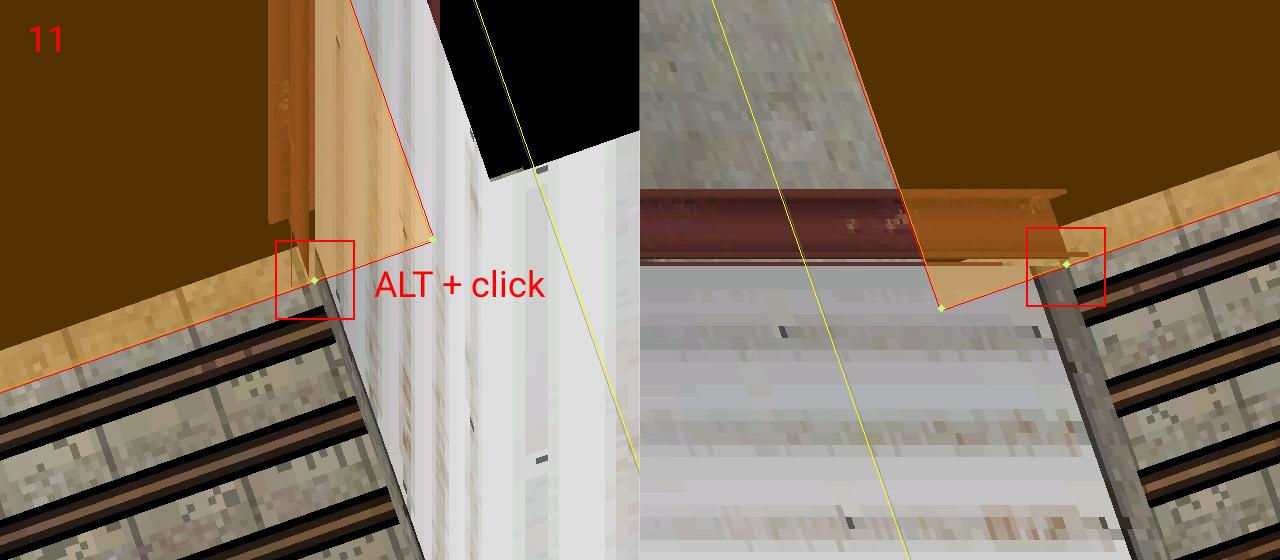
11 – Add a new vertex (using ALT + click) to the intersection of the polygon with the opening. Do the same on the opposite side of the doors (with an appropriate isometric view angle)
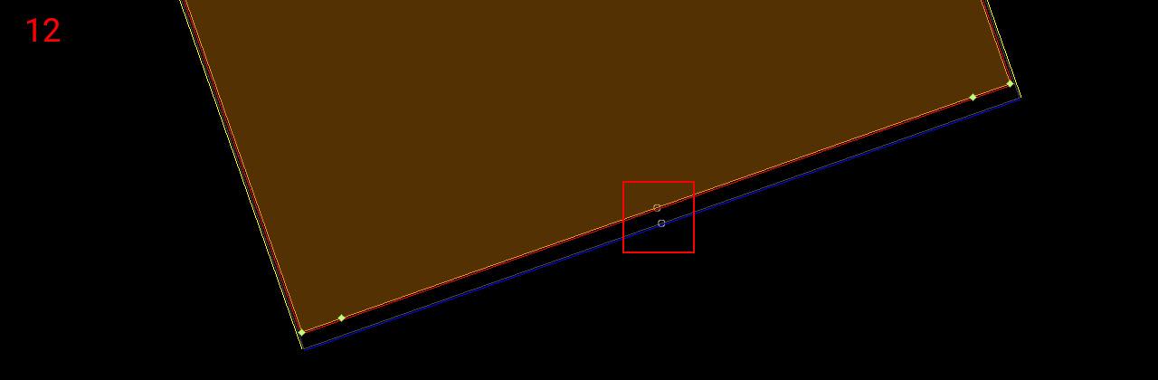
12 – Now rotate polygon segments (Ctrl + R) to get the first segment (white circle) to the corresponding position with the exterior facade polygon. This is very important for the alignment of both facades!
13 – Set the proper wall type to the opening (and other walls eventually). The Interior is done – you can lock the shape.
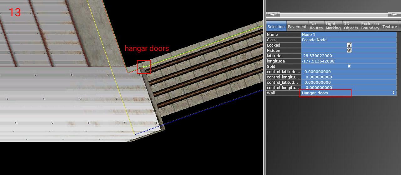
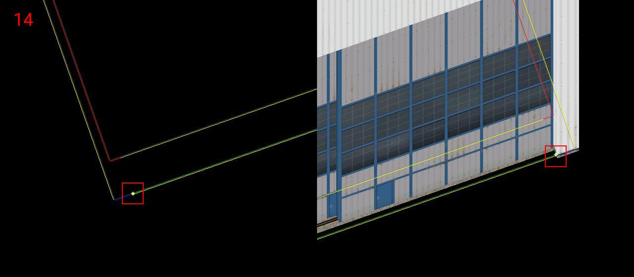
14 – Choose the door facade you want (lib/airport/hangars/flat/parts/hangar_door_xx.fac) and draw a single-segment polygon. Points should be placed exactly on the border of the exterior facade polygon (blue segment). Use the isometric preview to fit both endpoints.
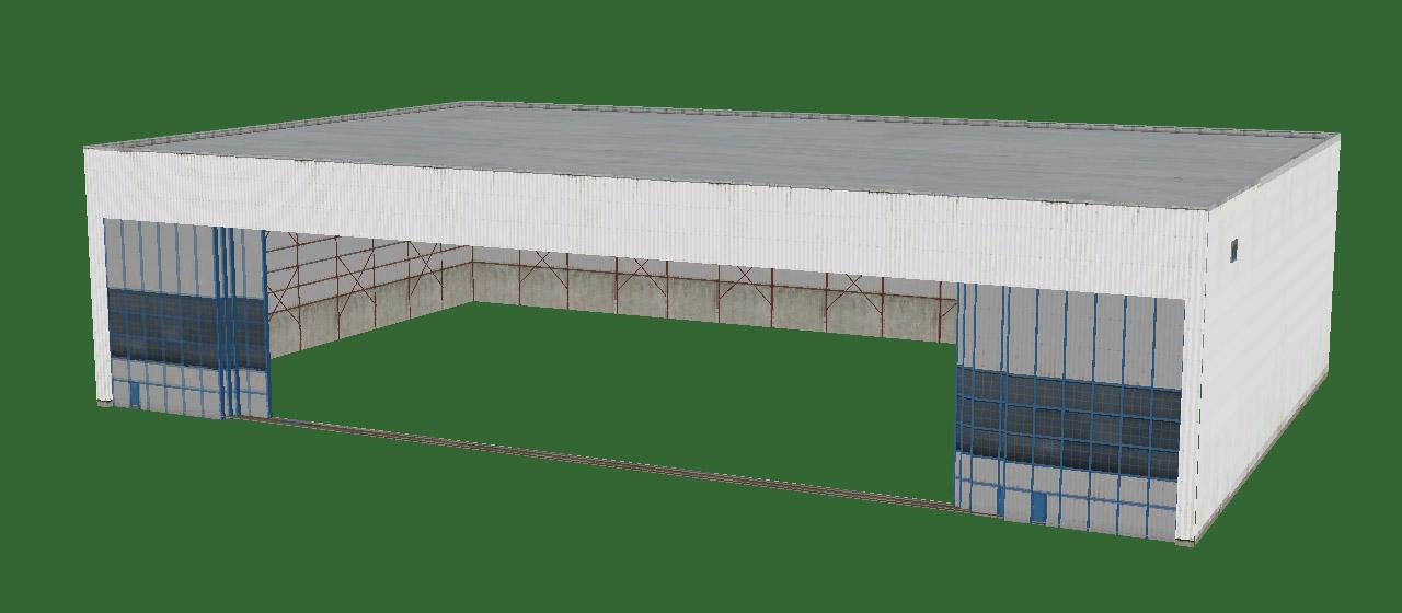
15 – Set the corresponding height of the doors (matching hangar height levels – 8, 10, 12, 16, 18, 22, 26, or 30) and set the wall type to "Hangar_doors_open". You are done!
NOTE: All standalone door facades also have a wall with closed doors (Hangar_doors). This makes no sense in combination with the interior of course. But you can use it for making any combination of the exterior facade design and doors. In that case, you don't need to worry about the interior facade but everything else above is still true.
Ground power provides electrical power to a parked aircraft, so its systems can be operated without depleting the battery even if the engine(s) are turned off.
The ground power plug must be plugged into the aircraft first, then a relay can be closed to actually connect an electrical bus to the external power source.
Plugging the power in
Aircraft made for X-Plane 12.07 and earlier always have voltage on the ground power receptacle if the aircraft is stationary (ground speed is less than 1 knot).
Aircraft made for X-Plane 12.0.8 need to call for ground services to have the ground power plugged in. In order to that, preconditions must be met:
The aircraft must be stationary (ground speed less than 1 knot)
The aircraft must not be on a runway (it needs to be on a ramp or taxiway area, or on grass)
Then, the user can request to “service the aircraft”. This will cause power to become available. Whether an animated ground power unit will show up in the 3d world to service your aircraft depends on
the aircraft author must have specified a location for the generator cart to be parked relative to this aircraft. That’s in Plane Maker, in the “dock ports” tab, “has ground power cart” must be checked and the coordinates specified
the airport must have a route for ground service vehicles to reach your aircraft parking position
In the absence of the above, the electrical power will still work, but no animated generator cart will be visible.
Making contact
Once the power is available, the available voltage will be readable in the sim/cockpit2/electrical/GPU_generator_volts dataref. If this reads 0, nothing is plugged in. This information can be used by aircraft to power “hot buss” items that might be available even before the switch in the cockpit is activated. This can also be used to indicate the availability of ground power to the pilot, such as the switch lighting up.
Now, the dataref sim/cockpit2/electrical/GPU_generator_on can be used to switch the GPU relay to on. Now, all connected busses will be powered from GPU power, all equipment can be used and the batteries will be getting charged.
Third-party overrides
At some third-party scenery airports, or with some aftermarket aircraft, the use of X-Plane default ground services might be undesirable. For these, the ground power can be overridden by plugin logic, so the third party product can decide ground power availability rather than X-Plane’s ground service system.
To take control of the GPU power, the plugin needs to set sim/operation/override/override_GPU_volts to 1 and then write the desired voltage to sim/cockpit2/electrical/GPU_generator_volts or 0 if the GPU isn’t supposed to be plugged in right now.
In order to not fry any virtual circuits, the plugin should check the dataref sim/aircraft/electrical/acf_nom_gen_volt to find out whether the user aircraft expects 12V, 28V, 110V or anything else.
The old weather datarefs have been marked as deprecated in X-Plane 12 and replaced with two new sets. The old ones will remain in place but anything referencing them should be changed to use the new ones as soon as possible. The good news is that this should be fairly straightforward.
Previously the values returned in the datarefs were relative to the user's aircraft. This was fine for handling instrumentation but not ideal for working with the wider environment. There are now two similar sets of datarefs, one for the weather at the aircraft's exact position, and one for the surrounding region.
Aircraft
In general, all the old datarefs that lived under sim/aircraft/ have been moved under sim/weather/aircraft/ with very similar names. The only real thing to note here is that in some cases, units have changed. Also, all these aircraft-specific datarefs are read-only. This makes sense; the aircraft's immediate environment is a point sample from the regional weather.
Cloud, wind and turbulence datarefs are no longer represented by individual datarefs with an array-like notation, they are handled as real arrays. This means you should do proper array handling of these by querying the size of the array using XPLMGetDatavf() before your first read, and allocating enough space accordingly. Doing this will allow your code to continue to work with no changes if in the future the array size is changed. Temperature and wind arrays have already been increased to 13 elements from 3.
It's important to remember that the aircraft's immediate environment is a snapshot of a single point in a simulated 3D volume. This volume contains deliberate variations from whatever the base weather is, whether that's a fixed preset coming from the UI or a composite of available real-weather data if this is enabled. You should not, in other words, expect any value reported at the aircraft's position to exactly match any value you may see elsewhere that isn’t based on the aircraft’s position.
Region
New for X-Plane 12, the base weather that defines the aircraft's surrounding region is provided as a distinct set of datarefs under sim/weather/region/. Right now 'region' roughly corresponds to a square degree but this may vary in the future. The region base values determine a starting point for X-Plane's own weather simulation, which gets added on top. As with the aircraft's datarefs, this means that you should not expect any value returned in these datarefs to exactly match any value you see elsewhere since the weather at any given point is taken from the combination of the base weather and the weather simulation, not the starting data for that simulation.
Atmospheric Altitude Levels
Atmospheric temperatures are defined at preset altitudes which can be found in sim/weather/region/atmosphere_alt_levels_m . If you are working with temperatures aloft, please use the altitudes given in this array and don't hard-code them. The altitudes, or the number of layers, may change.
Modifying the Region
Most of the regional datarefs are writeable, meaning that you can use these to change the weather in a large volume surrounding the user's aircraft.
sim/weather/region/change_mode
This controls X-Plane's internal weather simulation, when used with static weather, by setting a general trend over time.
sim/weather/region/variability_pct
This controls the internal weather simulation's variability for those parts which use random noise to generate variation. The base weather also varies with distance from a given reference point. Typically the reference point would be the selected airport if you use the UI to select a weather preset, for example.
sim/weather/region/update_immediately
When this is non-zero, any changes to any regional dataref except clouds will take place immediately. Otherwise, the changes will start to fade in over a short period of time, currently 1-2 minutes. Clouds are handled a little differently because there is a delay between the cloud data being determined and the results of the GPU-based cloud simulation being returned. Even with update_immediately set to true, clouds will generally take a minute or so to update to the new values. When you absolutely, positively got to kill every cumulonimbus in the room, you can use the sim/operation/regen_weather command to trigger an immediate full reset of the current weather.
API Access
For simpler access if you are using a programming language that can use it, the X-Plane SDK contains some basic weather data access functions. These allow you to get a weather snapshot – that is, the equivalent of the aircraft datarefs, the output of the base weather plus the weather simulation – at a specific point.
While you are free to request weather for distant locations, the accuracy of the data returned will drop significantly outside of the current region. Errors are reported via the standard XPLMSetErrorCallback() mechanism.
X-Plane 12 features a 3-D HUD – besides drawing HUD markings on top of the 3-d scene, the HUD aligns to the world in 3-d with the same parallax error that a real HUD would have, and looks “far away” to a user in VR.
The HUD consists of three separate authoring elements:
An area of the aircraft’s 3-d panel texture that has HUD markings.
A 3-d mesh in an aircraft attached object with appropriate objects, that will serve as the HUD glass. The HUD image will only appear when the glass covers the screen space area in front of where the pilot “perceives” the HUD to be.
Plane-Maker settings to calibrate the 3-d HUD’s alignment.
Setting Up the HUD in Plane-Maker
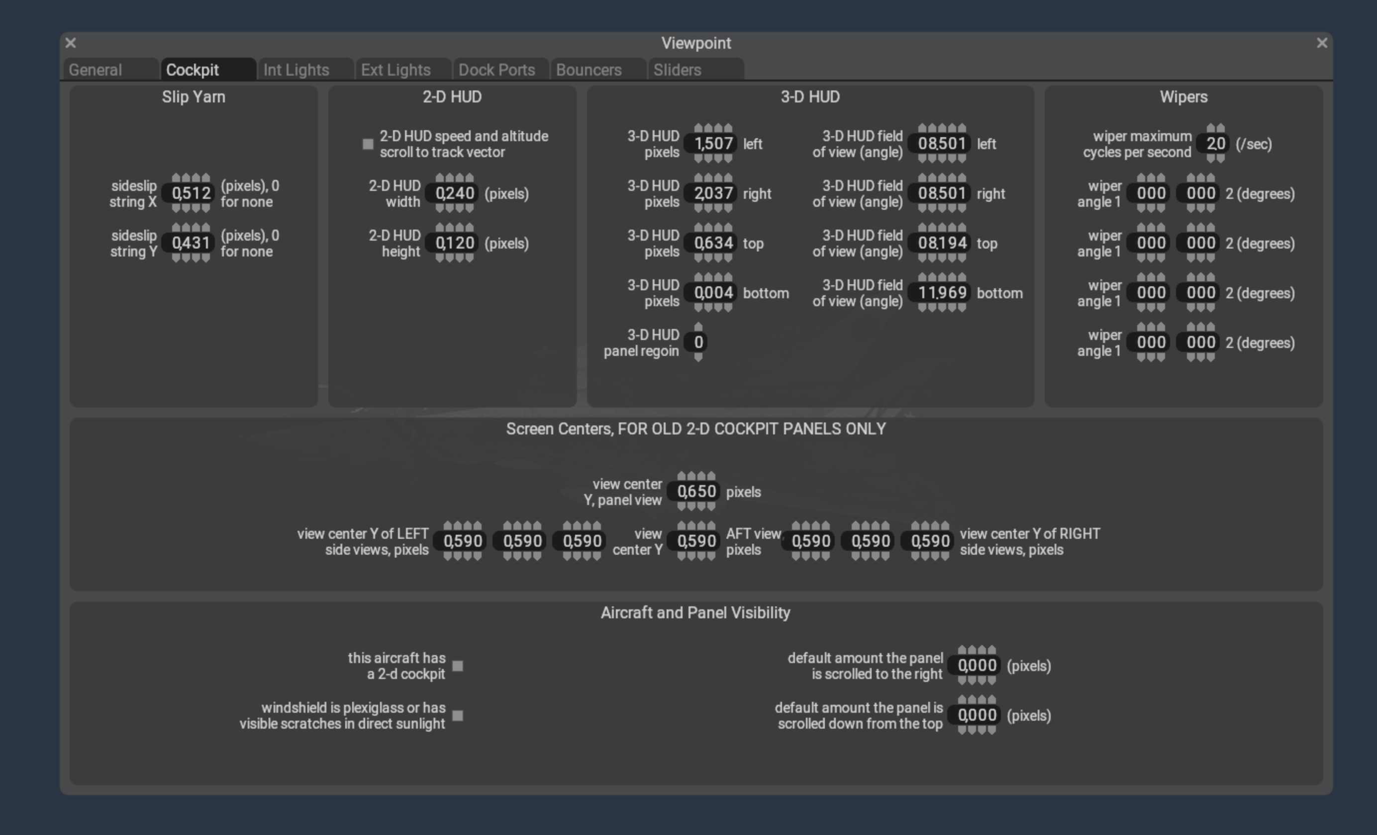
Plane-Maker’s viewpoint cockpit screen contains a section “3-D HUD” that requires three types of information:
The field of view angles of the edge of the HUD glass. You may need to calculate these in your 3-d model – it is the number of degrees to the left, right, up and down from from the pilot looking straight ahead at the default pilot viewpoint.
The pixel position on the 3-d texture panel that the HUD image will be taken from. The lower left is 0,0, and the unit is pixels. You will be able to see this rectangle in the panel editor to validate that it is correctly set up, but it must be changed in the viewpoint cockpit screen.
The panel region. If your 3-d cockpit uses panel regions, pick the region number for the HUD here. If your aircraft does not use panel regions, you should leave this as the default “0” value.
Creating the HUD Graphics
In the 3-d panel editor, click the HUD icon in the upper right button bar (just to the left of the “2-D” icon) to view the HUD preview lines. If the panel is set up with a 3-d HUD, you will see:
A cyan box showing the edge of the HUD’s image and
A HUD ladder showing the horizontal center, horizon, and 2.5 degree vertical increments.
You can use these queue marks to calibrate your HUD graphics.
⚠️ WARNING: as of X-Plane 12.0.8 the “2-d” HUD instruments only work in the 2-d HUD, and the “3-d” HUD instruments only work in the 3-d HUD. We recommend using generic instruments for the 3-d HUD.
Setting Up the 3-d HUD Object
The 3-d HUD needs a glass element in an object, with a special attribute
    ATTR_hud_glass
    TRIS	36 18
    TRIS	54 18
  ATTR_hud_reset
Steps to Debug The HUD
First, confirm the HUD image is present by using the texture browser to view the night panel texture.
Second, confirm the HUD glass is present by temporarily removing the HUD glass attributes and giving it a debug color texture.