Per-pixel lighting is something I hope to have in X-Plane soon. A number of other features will take longer, and quite possibly might never happen. This is the “pie in the sky” list – with this list, we’re looking at higher hardware requirements, a lot of development time, and potential fundamental problems in the rendering algorithm!
High Dynamic Range (HDR) Lighting
HDR is a process whereby a program renders its scene with super bright and super dark regions, using a more detailed frame-buffer to draw. When it comes time to show the image, some kind of “mapping” algorithm then represents that image using the limited contrast available on a computer monitor. Typical approaches include:
- Scaling the brightness of the scene to mimic what our eyes do in dark or bright scenes.
- Creating “bloom”, or blown out white regions, around very bright areas.
Besides creating more plausible lighting, the mathematics behind an HDR render would also potentially improve the look of lit textures when they are far away. (Right now, a lit and dark pixel are blended to make semi-lit pixels when far away as the texture scales down. If a lit pixel can be “super-bright” it will still look bright even after such blending.)
Besides development time, HDR requires serious hardware; the process of drawing to a framebuffer with the range to draw chews up a lot of GPU power, so HDR would be appropriate for a card like the GeForce 8800.
While there aren’t any technical hurdles to stop us from implementing HDR, I must point out that, given a number of the “art” features of X-Plane like the sun glare, HDR might not be as noticeable as you’d think. For example, our sun “glares” when you look at it (similar to an HDR trick), but this is done simply by us detecting the view angle and drawing the glare in.
Reflection Mapped Airplanes
Reflection maps are textures of the environment that are mapped onto the airplane to create the appearance of a shiny reflective surface. We already have one reflection map: the sky and possibly scenery are mapped onto the water to create water reflections.
Reflection maps are very much possible, but they are also very expensive; we have to go through a drawing pass to prepare each one. And reflection maps for 3-d objects like airplanes usually have to be done via cube maps, which means six environment maps!
There’s a lot of room for cheating when it comes to environment maps. For example: rendering environment maps with pre-made images or with simplified worlds.
Shadows
Shadows are the biggest missing feature in the sim’s rendering path, and they are also by far the hardest to code. I always hesitate to announce any in-progress code because there is a risk it won’t work. But in this case I can do so safely:
I have already coded global
shadow maps, and we are not going to enable it in X-Plane. The technique just doesn’t work. The code has been ripped out and I am going to have to try again with a different approach.
The problem with shadows is the combination of two unfortunate facts:
- The X-Plane world is very, very big and
- The human eye is very, very picky when it comes to shadows.
For reflections, we can cheat a lot — if we don’t get something quite right, the water waves hide a lot of sins. (To work on the water, I have to turn the waves completely off to see what I’ m doing!) By comparison, anything less than perfect shadows really sticks out.
Shadow maps fail for X-Plane because it’s a technology with limited resolution in a very large world. At best I could apply shadows to the nearest 500 – 1000 meters, which is nice for an airport, but still pretty useless for most situations.
(Lest someone send the paper to me, I already tried “TSM” – X-Plane is off by about a factor of 10 in shadow map res; TSM gives us about 50% better texture use, which isn’t even close.)
A user mentioned
stencil shadow volumes, which would be an alternative to shadow maps. I don’t think they’re viable for X-Plane; stencil shadow volumes require regenerating the shadow volumes any time the relative orientation of the shadow caster and the light source change; for a plane in flight this is every single plane. Given the complexity of planes that are being created, I believe that they would perform even worse than shadow maps; where shadow maps run out of resolution, stencil shadow volumes would bury the CPU and PCIe bus with per-frame geometry. Stencil shadow volumes also have the problem of not shadowing correctly for alpha-based transparent geometry.
(Theoretically geometry shaders could be used to generate stencil shadow volumes; in practice, geometry shaders have their own performance/throughput limitations – see below for more.)
Shadows matter a lot, and I am sure I will burn a lot more of my developer time working on them. But I can also say that they’re about the hardest rendering problem I’m looking at.
Dynamic Tessellation
Finally, I’ve spent some time looking at graphics-card based tessellation. This is a process whereby the graphics card splits triangles into more triangles to make curved surfaces look more round. The advantage of this would be lower triangle counts – the graphics card can split only the triangles that are close to the foreground for super-round surfaces.
The problem with dynamic tessellation is that the performance of the hardware is not yet that good. I tried implementing tessellation using geometry shaders, and the performance is poor enough that you’d be better off simply using more triangles (which is what everyone does now).
I still have hopes for this; ATI’s Radeon HD cards have a hardware tessellator and from what I’ve heard its performance is very good. If this kind of functionality ends up in the DirectX 11 specification, we’ll see comparable hardware on nVidia’s side and an OpenGL extension.
(I will comment more on this later, but: X-Plane does not use DirectX – we use OpenGL. We have no plans to switch from OpenGL to DirectX, or to drop support for Linux or the Mac. Do not panic! I mention DirectX 11 only because ATI and nVidia pay attention to the DirectX specification and thus functionality in DirectX tends to be functionality that is available on all modern cards. We will use new features when they are available via OpenGL drivers, which usually happens within a few months of the cards being released, if not sooner.)
Before I post anything to my blog saying what might happen, standard disclaimers:
- This blog represents my rambling about the directions I am considering for X-Plane’s rendering engine.
- This blog is not a promise or commitment of any kind to deliver any particular feature.
- If I say I am looking at doing feature X, and feature X does not materialize, either in the near or far future, or, like, ever, consider this to be one big fat “I told you so.”
With that in mind, I think the direction for lighting in version 9 is to introduce per-pixel lighting.
I don’t know what other set of features we’ll get with per-pixel lighting, but I am reviewing normal maps, specular maps, and the material attributes. Per pixel lighting will mean smooth, round, shiny looking surfaces without using a huge number of triangles.
Now there are two sets of hardware that will not be able to support per-pixel lighting:
- Cards without pixel shaders. (GeForce 2,3,4, Radeon 7000-9200.) You might know your card does not have pixel shaders because the pixel shader check box is not available in the rendering settings.
- Cards with first generation shaders. (This is the GeForce FX series and the Radeon 9500-9800 and X300-X600.) These cards can actually perform per-pixel lighting, but they are so slow that per-pixel lighting will bring them below minimum frame-rate.
So unfortunately, there will be an authoring decision: add more triangles so that per-vertex lighting looks good, or use fewer triangles and rely on per-pixel lighting. The decision will depend on what hardware you want to target at what performance level. (For what it’s worth, hardware that cannot support per-pixel lighting usually isn’t very powerful, so there is something to be said for not having a lot of triangles on these lower end machines.)
X-Plane 8 provides a useful baseline for rendering technology:
- It is finished and unchanging.
- Its use of shaders is very minimal, so even lower-end hardware can show the “X-plane 8 model” of lighting.
- X-Plane 8 rendering is completely supported in X-Plane 9. (That is, turn off shaders, and OBJs should look the same in X-Plane 8 and 9.)
So what do we have, and is it any good? Well, we have:
- Per-vertex lighting. Lighting is calculated per vertex, and interpolated between vertices.
- Very limited materials. Basically you can use attributes to set emissive lighting (so your day texture stays bright when back-lit, like taxiway signs) and shininess (to induce white specular hilites). The shininess ratio isn’t very flexible, but it does match what the built-in ACF shiny property does.
- Very fast vertex output within a batch.
I looked at some nice third party planes before writing this up, and one thing became clear: X-Plane can output a lot of vertices in an object if they are batched, and authors are using this aggressively. The advantage of just using a lot of vertices is: curved surfaces look round, the errors that are induced by per-vertex lighting are less ugly, and the object looks the same everywhere (because this path isn’t dependent on having pixel shaders).
The big weakness of the current situation is that you have to burn a lot of vertices to get close to per-pixel lighting, particularly for very shiny surfaces. I saw at least one plane (I do not recall who authored it) that just had more triangles in the engine nacelles than you could imagine. They look beautiful even in X-Plane 8 – great specular hilites. But that eats into your vertex budget pretty severely – it’s not a technique that you could use for every static airplane on a tarmac at LAX.
The triangle is at the heart of 3-d modeling – but before we discuss what might become of the triangle, we need terminology.
- Per-vertex lighting. This means that the brightness of the model (a function of the sun and camera position, etc.) is calculated for each vertex in the model, and then crudely interpolated between the vertices to light the pixels.
- Per-pixel lighting. This means that the brightness of the model (a function of the sun and camera position, etc.) is calculated for every pixel on the screen separately.
- Tessellation. This is the process of splitting a triangle into a number of smaller triangles, increasing the number of vertices in a model.
- Specular lighting. The specular lighting component is an extra amount of brightness that you get when the angle from the sun to the model to your eye is very small. (That is, if the model was a mirror and you could see the sun by looking at a certain location, then that location would have a bright “specular hilite”.)
- Normal map. A normal map is a texture that describes the way light bounces off a surface. This is one way to do “bump mapping”. This tutorial shows a pretty good example of how normal maps work. (The earth orbit textures in version 9 use normal maps to create “bumpy” mountains when pixel shaders are in use.)
- Specular map. A specular map is a texture that describes how strong the specular component of the lighting model appears for a given textured location. Here’s another tutorial that explains it.
- Environment Map. An environment map is a texture that represents the world around an object, used to simulate reflections. Here’s another blender tutorial that explains it better than I. (The reflective water in X-Plane 9 is effectively using a dynamic environment map created by taking a picture of part of the sim’s world every frame,)
- Material attributes. These are OBJ attributes that change the lighting model. For example, ATTR_shiny_rat changes the lighting model so that specular hilites appear.
- Batch. A batch is a single set of triangles sent to the graphics card without any change of mode. Basically every TRIS command in an OBJ becomes a batch; submitting a batch requires the CPU, but submitting a bigger batch (more triangles) does not require more CPU.
That’s enough vocabulary to describe just about everything that is happening now, will be happening in the future, as well as some pie-in-the-sky stuff. 🙂
The choice of panels (2-d panel vs. 3-d panel) for your cockpit and the choice of OBJ commands (ATTR_cockpit vs. ATTR_cockpit_region) both affect how your 3-d cockpit looks. Since these two techniques can both be varied, there are a lot of combinations, and 920RC2 does not have the right behavior. (RC3 will fix this I think.)
2-d vs. 3-d Panel
The 3-d panel is a new flat panel whose purpose is to provide the image for ATTR_cockpit or ATTR_cockpit region. Building a new panel for 3-d has a few advantages:
- The instruments can be packed together – no need for windows or other texture-wasting elements. This can help reduce panel size — panel size is expensive when using ATTR_cockpit_texture.
- The 3-d panel can be smaller than the 2-d panel; having a huge panel feed the 3-d object is slow.
- Instruments that are drawn with perspective in the 2-d panel can be redrawn orthographically, which is more useful for texturing real 3-d overhead panels.
Because the 3-d panel is meant only to be used as part of a 3-d cockpit object, spot lights and flood lights are not available, nor is a night-lit alternative. Why not?
- Such customized 2-d lighting would not match the rest of the 3-d cockpit visually.
- We will eventually have a more global lighting solution.
Basically I don’t want to provide features that will clash with the future implementation and eat framerate! The 3-d panel is aimed at next-generation content.
ATTR_cockpit vs. ATTR_cockpit_region
ATTR_cockpit_region provides a new alternate panel texturing path that gets rid of legacy behavior for improved performance and image quality.
- ATTR_cockpit_region requires the region be a power of 2, which saves VRAM. (If your panel is 1280×1024, then ATTR_cockpit rounds it to 2048×1024. Yuck!)
- ATTR_cockpit_region grabs the lit and unlit elements of the panel separately, and can thus provide lighting that is consistent with the rest of OBJ.
- ATTR_cockpit_region does not preserve transparency (which isn’t a good way to model a 3-d cockpit performance wise) – removing the alpha feature improves framerate and saves VRAM.
- ATTR_cockpit_region lets you pick out parts of a panel to texture only what you need.
This last point is less important now that we have 3-d panels (ATTR_cockpit_region came first) – it was meant to let you pick out a small subset of a large size 2-d panel, skipping windows. But if, for example, you need more than 1024×1024 pixels of panel texture, two cockpit regions are better than one 2048×1024 – some graphics cards hit a performance cliff when a cockpit or region exceeds 1024×1024.
Expected Behaviors:
(Under all situations, the instrument brightness rheostats should be preserved correctly.)
ATTR_cockpit + 2-d panel:
- The 3-d cockpit should look exactly like the 2-d cockpit.
- The 2-d panel is used as source.
- Panel transparency is preserved.
- Spot/flood lighting effects are available and work.
- Flood color is the forward flood color.
- The panel texture and object texture may not look the same under some lighting conditions.
ATTR_cockpit + 3-d panel:
- The 3-d panel is used as source.
- Transparency is preserved.
- Spot lights are not available, but flood flights work.
- Flood color is the side flood color.
- The panel texture and object texture may not look the same under some lighting conditions.
ATTR_cockpit_region + 2-d panel:
- The 2-d panel is used as source.
- Transparency is not available.
- Spot and flood lights are not available.
- Panel and object texture colors should match under all lighting conditions.
ATTR_cockpit_region + 3-d panel:
- The 3-d panel is used as source.
- Transparency is not available.
- Spot and flood lights are not available.
- Panel and object texture colors should match under all lighting conditions.
The Future
Basically both the 3-d panel and ATTR_cockpit_region are aimed at next-generation cockpits – they both strip legacy features to provide a clean platform for real 3-d cockpits. The expectation is:
- Global lighting will be applied to all 3-d geometry – panel texture and object texture. Non-emissive lighting (spot lights, flood lights) will apply to everything.
- Windows will be built using geometry, not alpha.
- The panel texture can be minimized by packing a 3-d panel and using regions. Manipulators let you provide interaction to regular object geometry.
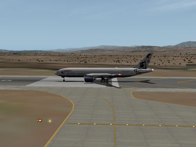
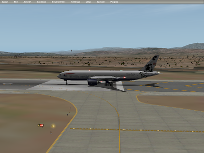
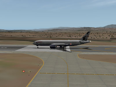
With X-Plane 920 RC1, the user can now control how smooth taxiway curves look. More smoothing looks better, but can slow frame-rate.
Below are four pictures of KSBD (which has good, sparse vertices) at the four rendering settings.

I was reading this blog post on the Microsoft Office binary file formats…to quote:
A normal programmer would conclude that Office’s binary file formats:
- are deliberately obfuscated
- are the product of a demented Borg mind
- were created by insanely bad programmers
- and are impossible to read or create correctly.
Hrm – deliberately obfuscated, a product of a demented borg mind, created by an insanely bad programmer, and impossible to read or write correctly…he must be talking about DSF!
But then Joel discusses why the formats are the way they are…tell me some of these don’t apply to DSF:
- They were designed to be fast on very old computers. (Sort of true for DSF – load time on low-end hardware was a DSF design goal.)
- They were designed to use libraries. (True – DSF is a lot less weird when you consider the layered structure, and relatively easy to work with via DSFLib.)
- They were not designed with interoperability in mind. (I’ll get to this later.)
- They have to reflect all the complexity of the applications.
In fact, the only reason Joel sites for byzantine Office formats that doesn’t apply to DSF is:
- They have to reflect the history of the applications.
In our case DSF is a new invention of X-Plane 8, so you don’t see a lot of past history artifacts in it.
The File Format as API vs. Data Container
File formats can serve two fundamentally different purposes:
- A file format can specify a data container, used to save information for use later. DSF fits this category: the purpose of the DSF is to hold scenery data in a compact and fast-to-read format for X-Plane. (The other goal of DSF is to be structured so that we don’t have to change it all the time.)
- A file format can be an interchange standard between two programs, similar to a programming API. DSF2Text text files are like that.
You pay for every design goal with more engineering time – if DSF had to be an interchange standard and a high performance data container, it would be a lot harder to design and probably not do either job terribly well.
X-Plane Owns Its Own File Formats
One of the decisions I made early on in my work with the X-Plane scenery system was to not try to use open standards for most parts of the scenery system. (OBJ8, DSF, these are X-Plane specific inventions.) Does this make me a closed-source fascist? Perhaps, but the intent was not to lock people out of X-Plane.
Instead the goal was to separate the problems of interchange and data storage in the places where the two would come into conflict. What became immediately clear was that we couldn’t meet all of our goals for performance, compatibility, and interoperability for a scenery file format with one giant scheme.
So instead we have DSF, whose goal is to be a cryptic but fast final step in the scenery pipeline, and we have DSF2Text and MeshTool, which take simpler text file formats, meant for interchange, and create DSFs.
The intended user of a MeshTool or DSF2Text text file is another program that is outputting its data format. Thus by forming a number of small links in a chain, no one file format is meant to be the “super-format” that has to do everything for everyone.
I am in Boston visiting family for the 4th of July, so there are a few compatibility bugs that I have seen but probably won’t be able to fix for a few days. Austin is still cranking out betas. So if new betas come out and these are not fixed, don’t panic – they are definitely on my todo list.
- Sceneries converted via FS2XPlane crash on load. It looks like this is due to a bug in the new threaded texture loader – I think you can work around this by turning off “load scenery in the background” in the rendering settings (but then loads will be slow). I have found the area where the bug occurs but haven’t isolated it.
- A user submitted a plane to us that crashes Plane-Maker on open – the panel code gets confused. I haven’t isolated it yet. If you have planes you’ve made, save the pre-920 versions!
- I think Benedikt’s x737 plugin should start working again in beta 2.
I have
blogged about correct airport layouts before, but let me bring the point up again, because it is so important:
- You must create structurally correct layouts (that is, vertices connecting to vertices, not lines) in order to get good rendering in X-Plane. Just because the preview looks okay in WED doesn’t mean your layout is correctly formed!
I wrote some documentation on the scenery site that describes the problems in more detail, with pictures.
(I’ve been trying to create more permanent documentation – it is tempting to simply blog the issues because it’s so easy to throw a blog post up, but after 110 blog posts in 2007, the scenery site is still very thin on the documentation front.)
Do Not Add Vertices To Make Smoother Curves
I really can’t stress this enough: please do not go adding extra vertices in your layout to make bezier curves look smoother in X-Plane. Why is this such a bad idea? Let me count the ways!
- X-Plane will fight you all the way! X-Plane adds vertices to curves (to make them smoother) when it detects large errors. If you have a lot of small curves, the errors are inherently smaller and X-Plane will add fewer points. So the first vertices you add to your curve do almost nothing. You have to add a huge number of vertices to get a marginal improvement in your curve. In the meantime…
- X-Plane will provide variable-quality curve rendering in the future! Curve detail should be a user-controlled setting. X-Plane has to run on a wide range of hardware; any time we can let the user pick rendering quality, this is a win, because it helps bridge the gap between the user who just bought a brand new Core 2 Extreme system with GeForce 9800 and the user trying to keep X-Plane 9 running on his G4 laptop which can’t be upgraded. When you add vertices, you take the decision about rendering quality out of the hands of the user, and force high quality on a user who may not be able to handle it. Adding vertices forces a decision of lower framerate on some users.
- Adding vertices bloats the size of apt.dat. This is not a huge factor for custom scenery, but is a factor for the default apt.dat. Robin received a big pile of new airport layouts, and that’s great. But one risk is that the total size of user submitted data could get out of control. For new layouts made with WED, vertices represent a big chunk of the data. If you are increasing your vertices by a factor of 5x or 6x to improve tessolation, you are bloating the apt.dat file.
- Manually adding vertices to smooth curves lowers the level of abstraction in the apt.dat file. Any time we can have a high level abstract representation of scenery, X-Plane has the freedom to improve rendering in the future. If your layout is made up of a large number of small curves (instead of a small number of large curves), X-Plane cannot tell that those small pieces make up some larger structure; in the future it may not be able to render those layouts as nicely as ones that are made with fewer control points.
In summary, please use the smallest number of vertices to create your layouts. (But always add vertices to ensure that your T junctions are correct!)
I seem to be in a philosophical mood these days with my blog posts…thought for the day: the human mind easily goes from the specific to the general. Our brains are generalizing machines, pattern matchers finding the rule in the noise.
My preference in creating new scenery-system features is to make them very limited, and my reasoning is: our brains don’t go backward very well. We do not go from the general to the specific.
Now you might think: when making a scenery-system addition, the best thing would be to have a general feature, more useful because it can be used everywhere. But I say: the most important thing is to fully understand the feature – otherwise the feature comes out buggy.
(Consider the piles and piles of bugs and weird behaviors that you get when combining OBJ animation with OBJ hard surfaces.)
Since the human brain doesn’t go from general to specific well, it is hard to start with a rule (“let’s allow feature X in all parts of the scenery system”) and comprehensively derive all of the implications; it is human nature to be surprised later by some unintended side-effects.
It is always easier to extend a feature later to its natural full implications than to declare certain uses illegal later, after authors of planned or started trying to use the feature in that way. If the generalization of the feature makes sense, extending it is often quite painless.
Texture Paging – Scope For Now
Texture paging is the ability for X-Plane to raise and lower the resolution of scenery textures dynamically as you fly. This means more VRAM used for nearby things and less for far away things. In practical terms, this reduces VRAM used by orthophotos by down-sampling the far-away textures, making larger orthophoto scenery packages possible. As you fly, the sim reloads some textures at higher resolutions and some at lower. The cost of the features is the load time while you fly, which burns up some extra CPU cores.
It is my hope that we will productize some very simple texture paging in the next major patch of X-Plane 9 (that would be 920, not 902). But the usage will be pretty specific:
- Texture paging will only be available for .ter and .pol textures (we can extend to other scenery types later if it makes sense).
- Texture paging will require changing the .ter and .pol files (X-Plane will not automatically analyze your scenery to see what can be paged.)
- Texture paging will not be available for ENV scenery.
- If you share textures and texture page, the results will probably be really bad and cause chaos. Be sure to use only one .ter or .pol file (and reference that text file only once in the your DSF definitions section) if you want sane paging. We can extend paging to shared textures in the future, but for now orthophotos are the intended target.
I am also deferring work on dataref-driven textures; we’ll get there eventually, and the infrastructure from the pager will make it easier. But dataref-driven textures really need to be available in a lot more places – it’s a bigger, more complex feature* and I can’t keep adding scope to 920.
Make New Meshes!
While paging will be available for both overlays (using .pol files) and base meshes (using .ter files) I strongly, strongly recommend going the base-mesh .ter route. RealScenery sent me their new “State of Washington” package to use as test material; I was pleasantly surprised at the high framerate. Part of that comes from them using base meshes and not overlays.
Overlays cause the sim to draw the scenery twice (first the old scenery, then your overlay), burning a lot of pixel shader and fill power. Base meshes simply replace the old mesh which is at least twice as efficient.
(I’m just going to keep beating the dead horse of base meshes because I believe that the sooner everyone moves toward base meshes, the more bang for our hardware buck everyone gets.)
* In particular, remember that texture paging happens on threads. But datarefs can come from plugins that are not threaded! Insert anarchy here…


