In my previous blog post I defined a split vertex in an airport layout and described how they can be simulated in an apt.dat pile using multiple points.
Now that WED is in public beta and people can easily make split beziers, many have noticed the “split bezier” bug in X-Plane 860:
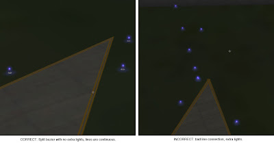
This is a vertex that is split…on the left you can see what it should look like – on the right you can see what it does look like. There are two problems going on:
- The taxiway lights have gone crazy at the split vertex. (This is what everyone sees.)
- The taxiway line is a bit jumbled at the split vertex too.
It should be noted that this bug will can also happen for any vertex (even unsplit) in rare occaisions due to interactions with the mesh. Same symptom, same buggy code, different cause.
The good news is:
- There is a workaround that will make the lights look correct and the lines acceptable in X-Plane 8.60.
- The workaround will be implemented inside WED – no need to change anything.
- When X-Plane is fixed, it will make the lines correct too.
In my next post I’ll describe the fix and what the results look like.
(This blog entry explains the background of split beziers – the next parts will explain the bugs that they cause and the workarounds.)
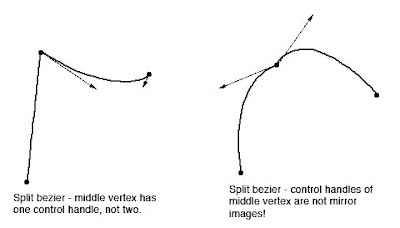
In apt.dat terminology, a split vertex is any vertex of a polygon where the control handles on either side of the vertex are not exact mirror images. (When there is only one control handle it is therefore by definition split!)
You need a split bezier any time you want to:
- Have a sharp corner between two curves and control the tangents of the curves or
- Have a sharp corner between a truly straight segment and control the curve of the next segment.
Split Beziers and apt.adt
Now here’s the rub: the apt.dat format does not allow for split beziers – each curved point has only one control handle – the other is calculated by x-plane by mirroring…thus no vertex can ever be split.
(This is due to a total lack of brains on my part when working on the apt.dat format, which is quite embarrassing considering how long I spent thinking about it.)
The Hack
There is a way to simulate a split bezier: if you use zero-length segments (that is, multiple points on top of each other), you can create a shape that works as if it is split.
In its simplest, a split bezier can be created by using 3 vertices.
- The first vertex uses the control handle of one side.
- The second vertex is not curved.
- The third vertex uses the control handle of the other side.
Why does this work? Well, a bezier curve between a curved point and a straight point has zero length if the two points are on top of each other. So what we’ve done is inserted two zero-length segments. The result of this mess is that the control handles on either “side” of this cluster of points can be different!
Is the second point really necessary! Yes! The reason is this: if we simply had the first and third point (two bezier points with different control handles), X-Plane would draw a loop from the first to the second. Remember: two colocated points with ONE control handle form a zero-length curve, but two colocated points with TWO control handles form a loop.
(To see this for yourself, just draw some examples in WED or photoshop. 🙂
Line Continuity
There is one more wrinkle we have to add to the puzzle in order to understand how this works, and what the pitfalls are: line continuity.
A bezier path (taxiway edge, linear segments, etc.) is made up of one or more bezier curves. Each curve has zero or more attributes.
When X-Plane draws the actual taxi lines and lights, it looks for continuous adjacent bezier curves with the same attribute and makes sure the linkage between those attributes is correct.
(This linkage is computed separately for each type of property. So if you have taxiway lines on two segments and lights on one, the taxiway lines will still link!)
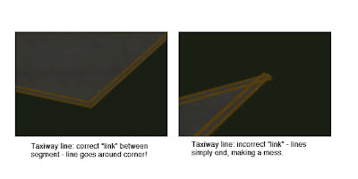
The picture above shows a correct vs. an incorrect link. When dealing with unsplit beziers and non-curved points, linkage is pretty much automatic, it just works.
But there is a pitfall to our above hack for split vertices: we have three points on top of each other. They must all have the same attributes in order for linkage to work. A “break” in the continuity of the line for one of the zero-length segments still counts as a break in linkage. The picture on the right was produced by creating a split bezier and removing the double-yellow-line attribute from the second of three vertices.
In my next post I’ll explain the bugs that this causes in X-Plane 8.60.
Something I’m seeing now that WED is in beta: airport layouts with the entire taxiway structure made from one really complex polygon.
I’m not really sure if this is a good idea. First the potential problems:
- I suspect that the creation of the taxiway layouts can get slow when the number of sides in the airport layout is really huge and there are holes. I don’t know this for a fact because we let the OpenGL libraries do the heavy lifting. Because this loading is done on a second CPU, it might not be noticeable to all users.
- The pavement can have only one texture direction per polygon, so multiple polygons may be necessary.
- Certainly in WED having a few large complex polygons slows down editing — if all else is equal, the tools work better with smaller polygons.
Now…overlapping pavement is generally bad (that is, there is a performance cost), but more sides are also expensive. More thoughts:
- The more square feet of overlap, the worse. So a small overlapping intersection is not so bad, but avoid layering a huge polygon on top of another huge polygon, which just strains the video card.
- Fewer segments are better. Consider two crossing taxiways…8 segments with overlap, but 12 by making a plus.
- But wait – the above example is misleading…if you need to change the light types so the blue taxiway lights don’t cross the intersection then you’ll need to add 4 more segments, so now it’s 12 and 12 – a wash. (In this case, having one big polygon is probably easier to manage.)
And for performance…
- Try going to your layout from far away and watch the last step of loading…if it starts to take a long time to “preload” things it means your layout might be a bit complex.
- Do not expect X-Plane to become faster at loading airport layouts…the limiting factors are proportional to complexity, so if you have a killer polygon now it’ll be pretty expensive later too.
One other note, from a conversation with Tom…WED splits vertices into a fixed number of segments (per zoom level) so splitting a bezier makes it smoother. X-Plane does not! X-Plane splits beziers based on the overall curvature, so adding more nodes without changing the shape has no effect.
So please do not try to use the split command to make X-Plane “smoother”. We’ll provide a rendering setting for this some day. The current value was chosen because anything smaller looks awful and you have to make it a lot bigger (read: a lot slower fps) to get an even marginal visual improvement.
In my previous post I mentioned that the scenery tools are separate code with a separate release schedule from X-Plane. This implies that the updates to the tool won’t be in sync with X-Plane. (The same thing is already true for the AC3D plugin and all of the wonderful third party tools that people have written.)
X-Plane’s scenery compatibility strategy is “backward but not forward”. In other words, if you open old scenery with a new X-Plane and it won’t open or looks different, that’s a bug (please tell us). You should never have to modify your OBJs or scenery if they are correctly made, and the definition of “correctly made” shouldn’t get more strict over time.*
Why no forward compatibility? Well, it’s possible to have syntactic forward compatibility (have X-Plane read a file it doesn’t understand because at the time of release the spec didn’t exist) but it’s not possible to have X-Plane display that file with any kind of sanity.
You could say “just leave out stuff you don’t understand”. Well, imagine if we had done that with apt.dat — imagine if X-Plane 840 tried to display an 850 apt.dat by simply skipping what it didn’t understand. Since taxiways are fully replaced with a new code, 850 layouts would have no taxiways at all if shown in 840. This is certainly unacceptable.
The only way around this would be to require all new features to have “fallback” content, e.g. have the file contain two copies of all taxiways. Since the structure of 850 and 810 taxiways are so different, this would basically require the author to do twice as much work…similar problems happen for animation commands, and missing datarefs.
So the content has to be older than the sim. What about tools?
Well, first, I don’t write the tools with forward compatibility. Since they are all free a user can easily get the newest tools to work (in a sane manner) with new content.
The tools do have to support old file formats though – we don’t usually post old copies of the tools (the AC3D plugin is an exception, since old versions work with old host copies of AC3D). Instead the tools are designed to support restricted file formats. For example, the AC3D plugin will export to OBJ7 or OBJ8 – authors targetting X-Plane 7 can export to OBJ7.
WED only exports apt.dat 850 files – this is by design from day 1, and it will not ever be an apt.dat 810 editor. (Use TaxiDraw if you need to do this.) However, as new X-Plane features emerge (and I am sure they will), WED will have options to target future X-Plane versions, or restrict the export to only features supported by older versions, perhaps with a warning if the WED document contains features that will be lost in an old export.
* One problem we have with this is: X-Plane isn’t a strict validator of scenery file formats, so it is possible to have mistakes in scenery that were always illegal by definition of the file format, but X-Plane doesn’t notice at first. When I detect a case like this, I try to make the problem a “warning” rather than have X-Plane quit, so that authors can get information on buggy files without users suffering too much. X-Plane will print only one warning per package per scenery load to keep things streamlined.
WED went public beta yesterday. You can find it under the tools section of the X-Plane scenery web page.
I want to say thanks to the users who helped me with the alpha testing of WED. These users tested new builds quickly, wrote up great bug reports, and put a lot of effort into using WED at a time when it was really no fun to use.* Thanks guys!!
To reiterate a few points about WED:
- WED 1.0 edits only apt.dat files, not DSFs or DSF overlays. WED will be the platform for additional editing features, but for now it only edits apt.dat files, and it will be like this for a while.
- WED is still in beta, so use caution! Save backups, save often! Save earth.wed files and export to apt.dat for extra safety.
- WED is free and open-source. It is not distributed with X-Plane, and you don’t need to buy X-Plane to use WED.
Enjoy!
* Remember, “alpha” software means “we can test all functions, but they could all be broken”, while beta means “we think there are no bugs that would cause data loss or crashes”. So…while WED was alpha, it tended to crash or trash files, so the alpha testers couldn’t get any real work done.
It’s that time of year – I will be away from all forms of technology next week, enjoying cool mountain air and not having email. When I return I will post an udpate on the status of WED.
Posted in Tools
by
Ben Supnik |
Mighty Mighty Bostones? Anyone? Nevermind. Anyway…
…some pictures of WED. (These were taken on a Macintosh, but it looks almost the same on Windows except for the title bars of the windows.)
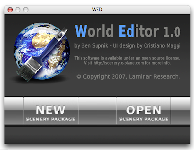
This is the startup window. WED can edit multiple scenery packages (in multiple windows) but does not let you edit a scenery package until you create and name it. So we show this window when you startup to let you choose between a new or existing project.
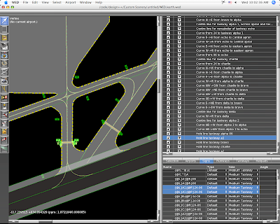
The left side is the map view, which provides draggable editing of any part of an apt.dat file. This is part of Aussie’s KSBD layout, which is part of the X-Plane demo. The right side provides a hiearchy-structure view (top) and more detailed editing or properties (bottom).
With the vertex tool, we can drag control handles for any selected entity.
The map view is a “structural” view, not a photorealistic one. The markings on the lines and pavement color change to reflect the settings you pick, but WED does not attempt to reproduce the final result in X-Plane.
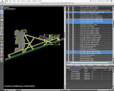
Wiht the marquee tool, we get a rectangular edit box around the selection and can thus resize or move whole sets of entities at once.
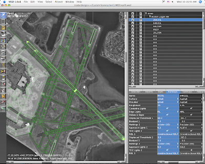
This is KBOS from 860 imported into WED. WED will import 810 or 850 layouts, but only exports 850 layouts. (It can thus be used as a simple converter.) That background image is automatically downloaded from terraserver and updated as you zoom and scroll the map. Unfortunately terraserver only covers the US; where there is no coverage you can import any BMP, PNG, JPEG or TIFF file and set it as a background image.
Posted in Tools
by
Ben Supnik |
Since before I’ve been involved in X-Plane, scenery has been broken into tiles. You know the naming scheme…+42-072.XXX is some kind of file for Boston. Perhaps it’s a .env or a .dsf, but what is unchanged is that the world is broken up into bite-sized pieces.
Tiling is very necessary for X-Plane…it allows the sim to rapidly load only the information we are interested in. The world is too big to go fishing for the relatively small amount of data that is loaded at one time.
The source data that is used to build global scenery is also tiled – if you look at the SRTM files, they often have names like N42W072. It’s no surprise that global data requires tiling to make it manageable.
When we produce global scenery, we work on a per-tile basis. We load the raw tiled data* into source XES files (one per tile), then process and convert that XES file into a DSF. By working one tile at a time, we limit how much RAM we need.
But if you used WorldMaker on an airport or city that spanned a tile boundary, you know how annoying tiling can be. With WorldMaker you couldn’t see both halves of an airport at once.
WED will not use tiles. For custom scenery packages, the total data is not so large that we have to tile. When you work on a scenery package in WED, you work on the entire package at once as a single seamless workspace. When you export your work, WED will split the data into tiles as needed. This will mean:
- You do not have to decide in advance where you are going to work. All scenery packages cover the entire planet, and DSFs are created only as needed.
- You will be able to work on more than one “tile” of area at a time, because there are no tiles.
- You will be able to work on airports that span tile boundaries seamlessly.
I just finished fixing some bugs in WED regarding the hierarchy view. (To get a sense of what a hierarchy view is like, try AC3D…)
In WED, the contents of your airport layout are viewed in a hierarchy view. This is where you reorder your runways and rename entities. You can also group entities (as many times as you want) to help organize your layouts. (The groups will not be visible in the final apt.dat.)
An airport is, in a way, sort of a super-group…it’s a group of “stuff” (runways, taxiways, etc.) plus it has its own information.
But this leads to some tricky situations:
- You can’t have an airport inside another airport.
- You can’t have a runway outside an airport.
The result is that there are a number of grouping and drag & drop combinations in the hierarchy that are simply illegal. Cris and I debated this a bit and what we have now is: commands that would produce illegal results simply cannot be executed. (That is, the group command is grayed out if the new group would violate these rules, and the drag & drop won’t show a legal drop if the new order would violate these rules.)
Once we get into beta we’ll see how well this works. The alternatives include:
- Putting up a specific error message when an illegal configuration is made (annoying).
- Allowing illegal configurations and putting up an error message on export (by this time the whole file layout could be pretty badly messed up).
- Attempting to silently export the illegal configuration (unpredictable – there’s really no good way to export an airport inside an airport).
Also, I am sure there are some illegal configurations I have missed…we’ll have to catch those in beta too.
Posted in Tools
by
Ben Supnik |
First, I just want to be clear: I am not announcing any future features for the scenery tools. I am not saying when they will be released, and I am not saying what they will do, because honestly I do not know. There have been too many cases when users have emailed me and said either “I thought you guys were going to do X” or “you guys promised you were going to do X”, so now I am officially paranoid.
So this blog post is not about what the future scenery tools will do – it is simply a discussion of the difference between editing source data and compiled DSFs.
When we make the global scenery, we start with a bunch of source data that roughly consists of: road maps, coastlines, elevation, landuse, climate data, airport locations, etc. When we build a DSF out of it, we “bake” these items together into a single file. During this baking process, our tools apply some “integration effects”. Here are a few of the more obvious examples:
- Terrain under airports is forced to be an airport grass texture, appropriate for local climate data.
- Roads are removed from airport areas.
- Intersections are computed for highways – that is, a highway and city street form an overpass, but two city streets become a real intersection.
- Generated Buildings are put around the roads, not under them.
- Buildings are oriented to “face” the slope of the ground they are under, based on their shape.
That’s not a complete list, but it gives you an idea of some of what goes into making a DSF. All of this information is precomputed and represented in the final DSF. But consider this last point: the DSF contains the actual orientation (north/south/east/west) of each building. It does not contain the slope underneath the building and it contains no information about which buildings need reorientation. In other words, the results of the process, not the inputs to the process, are present.
So consider what would happen if you could simply edit the data in the DSF:
- If you moved an airport, the airport grass would stay in its own location.
- If you moved an airport over a road, the road would still be there.
- If you changed a city street to a highway, it would not form an overpass.
- If you moved a road on top of a generated building, the building would remain in place.
- If you changed the ground elevation, buildings would not change their orientation to face the new slope.
If you changed the source data and re-ran the DSF building process, these effects would occur. But remember, we need elevation, land use, etc. to build a DSF from scratch, and the DSF itself doesn’t contain its source data.
So we have two possible strategies for editing DSFs:
- We could build a DSF “retouching” tool that let us make very small changes to the existing DSF without having any source data. None of these effects would “work” so authors would have to make very small changes and then hand-fix any problems that appeared.
- We could build a DSF “rebuilding” tool that let authors make new DSFs from source data. All of the effects would look good, but authors would have to get some of the source data. (We could post our source data, or provide links to places where it can be downloaded.)
Note that we can’t have our cake and eat it…we cannot get the “integration effects” listed above unless we go back to the source data. If I can stretch my cake metaphor to the breaking point, once we make our cake, we can’t easily remove the flour and add another egg – we need to start over with the raw ingredients.
Which strategy will the scenery tools use? I don’t know yet. I am focusing on airport and overlay editing, which sidestep this issue a bit (we can easily edit an apt.dat 850 or overlay from the final product). We may do a bit of both strategies – it depends on what users want and what we can code efficiently.
Why don’t the finished DSFs contain everything we need to edit them? The answer is size. The finished global scenery was about 56 GB of DSF. When I last checked, the raw data that forms the DSFs was at least 100 GB or more. So for each DVD we shipped of scenery, we’d have to ship two more DVDs of source data, for a 21 DVD set, most of which wouldn’t be useful to most users.


