In my previous post I provided a brief description of how we’re going to use OpenStreetMap data in X-Plane 10. How do you get involved? Map your area; improve the quality of OpenStreetMap where you live.
- If roads or waterbodies are missing, incomplete or wrong, fix them! If they’re missing information, add it.
- Please respect OpenStreetMap’s community. We are new guests in their house. Take a little time to learn about OSM and how their work proceeds.
- Get in touch with local OSM chapters for your area; there may be non-X-Plane OSM users working in your area already.
- Please create high quality mapping data, not just useful data for X-Plane. For example, X-Plane does not use street name information, but nearly everyone else who uses OSM does. If your street is missing, please add the name, not just the road type.
- When working on OSM, please try to make OSM match reality – don’t worry about what “looks good” in X-Plane. OSM should match real life, and X-Plane should do its best to recreate this view. Please do not hack OSM data to make X-Plane look better!!!! (I can’t think of any case where you’d want to do this – the scenery creation process works best when the data is accurate.)
A brief note to users in the United States: the US is a little bit different from other OSM countries because we have more free data than Europe. As a result, the US OSM data has been “seeded” with imports of data like TIGER and NHD. (For more on this, I recommend Steve Coast’s SOTM.US keynote video.) The result is that while unmapped areas in other countries tend to be empty, unmapped areas in the US are often filled in with data that is present but not particularly good.
So if you live in the US, take a look at your home town. Some of the most common problems are: incorrect road types or incorrect one-way information, missing bridges, and missing water bodies. To meet the level of quality that OSM already has in Europe (have you seen what the Germans have mapped?!?!) the imported free data needs a scrubbing by real human beings who know the area.
In my previous post I announced that we are using OSM for our vector data for the version 10 global scenery. But what data are we using exactly?
The short answer is: we are using road/rail/powerline data for our road grid and coastline/lake/polygonal river data for water bodies. This data replaces our use of TIGER and VMAP0 for those vector features.
We are not planning on using individual building data in the first global scenery cut from OSM; we don’t have the infrastructure for this yet. OSM has a lot of data, and it will take time to find ways to use it all in the global scenery. The distribution requirements of the global scenery also imply that we may not be able to use all of the data to its full potential due to the limits of DSF size.
OSM data comes with a tag scheme: a given way (line) or node (point) comes with one or more key/value pairs. The tag scheme is not limited or controlled; anyone can put any tag on any piece of data. (This usually shocks experienced GIS users when they first see it…it certainly astonished me. You really have to think of OSM as more of a Wiki and less of a database.) We only use certain tags for the global scenery.
The road tags we care most about are the tags that define:
- Road type (e.g. highway=)
- Bridges and tunnels (bridge, and layer – layers are important for getting stacking right).
- Oneway (which defines the traffic flow direction).
We may someday get clever and start using width, speed limits, surface, and the other interesting tags, but for getting a first version of the global scenery done, those are the big ones.
We try to use any area-style waterbody (e.g. natural=land/water, landuse=lake, etc.) as well as the coastlines defined by the natural=coastline tag.
Our general strategy is: if you can see land/water and road type on the map, we try to use it. In other words, we try to use the same tags the maps show so that people can see what the effects of their editing are.
We may have to augment water data with other data sources; OSM is often missing data, and while an area without roads is no worse than the old VMAP0 data, we don’t want to lose water that was visible in version 9. I do not know precisely how we will cope with this, but we will probably have to mix in other water data to complete the global scenery.
(We had to do the same thing in version 9: we combined the SWBD and VMAP0 water data to make complete world water, a strategy that gave acceptable but not beautiful results.)
There’s a lot of other interesting data we can use, and I do not know how far we will get with it in the first version. For example, vector polygonal parks are notated via the leisure=park tag; this can include giant state forests, so we can’t simply make all of these areas green. But we might be able to use them as a “hint” that the land class data should be interpreted with parks in mind.
I see our work with OSM data for the version 10 global scenery as the first step in what will be an ongoing process to include more and more data in the global scenery. But given the huge amount of ‘interactivity’ we pick up from OSM (e.g. for the first time, anyone can change the data we use, and for the first time, anyone can get their own complete copy of the data we use) we’ll need to evolve the global scenery process.
- I would like to make it possible for other people to render global scenery tiles; that way if you improve OSM data, you don’t have to wait 2-4 years for Laminar Research to recut the world. With a short cycle of editing, we need a short cycle of publishing. (This already exists for apt.dat – you can submit contributions to Robin and he publishes them in monthly data cycles.)
- I would like to make it possible for third parties to share their use of OSM tags with us and us to share our tags with them. Since the scenery tools have always been open source, this shouldn’t be a problem – our code to process OSM data is actually in our public source code repository now. (I will need to post the config files that have the OSM tags at some point.)
- The line between global scenery and custom scenery may become blurry. For example, if you download OSM data, carefully edit and tune it, recut a global scenery tile with it, and then add some custom buildings, is it global scenery or custom? I don’t know which it is, but OSM may make new ways to make custom scenery possible by making huge amounts of vector data available to everyone.
I think I’ve talked about this on forums, but the actual blog post I meant to write (months ago) has been sitting in my ‘drafts’ folder and it’s so obsolete that I’m just going to start again. So…
As you may have heard, X-Plane 10 is going to use OpenStreetMap (OSM) as our data source for vector road data and some fraction of our vector water-body data. X-Plane 9 uses TIGER and VMAP0, so switching to OSM will be a huge improvement.
If you haven’t looked at OSM, the very short version is that it’s a cross between Google Maps and Wikipedia: it’s a global map of vector data that anyone can edit. And unlike Google Maps, anyone can get the actual vector data and use it for any purpose. This makes OSM useful for creating global scenery.
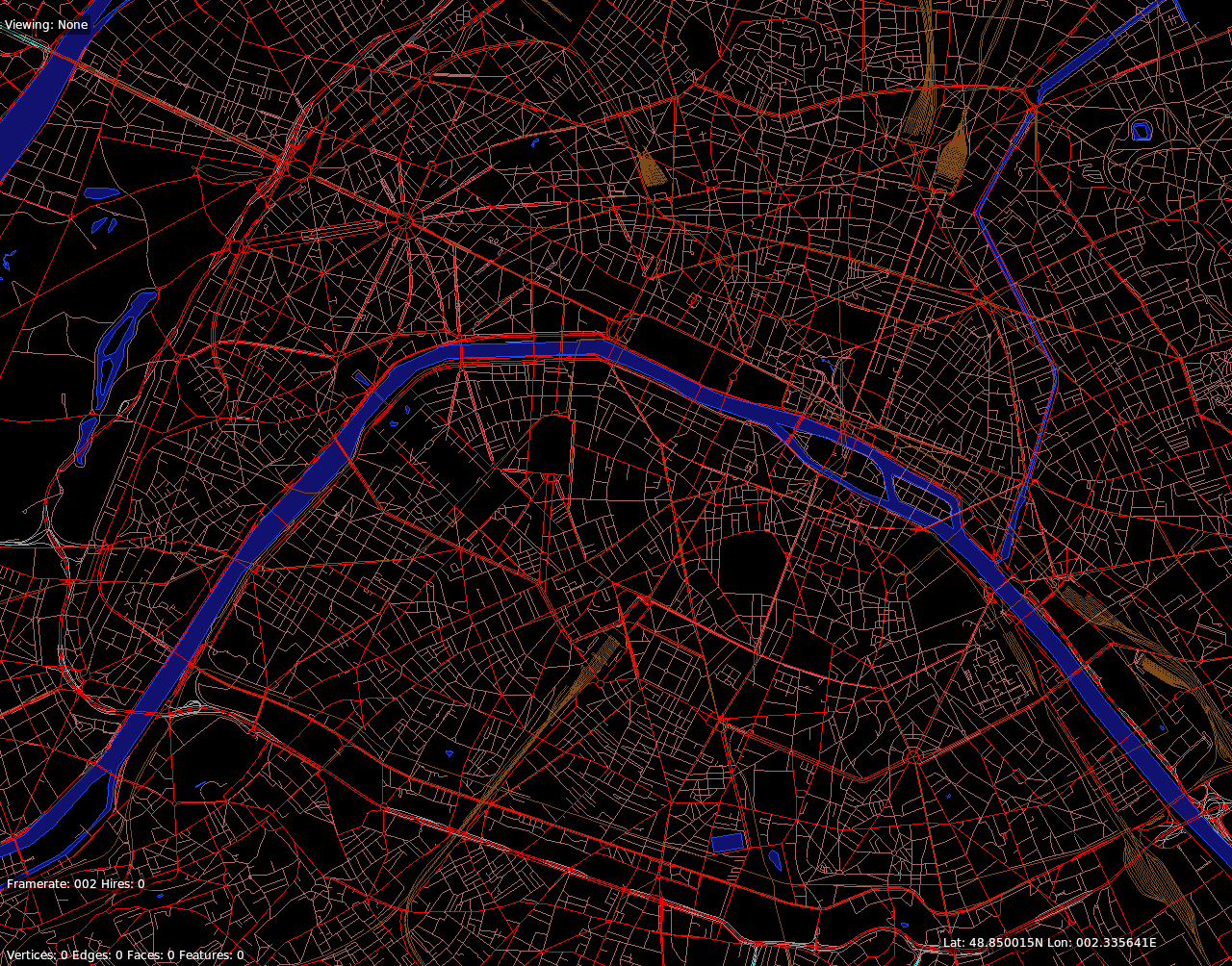
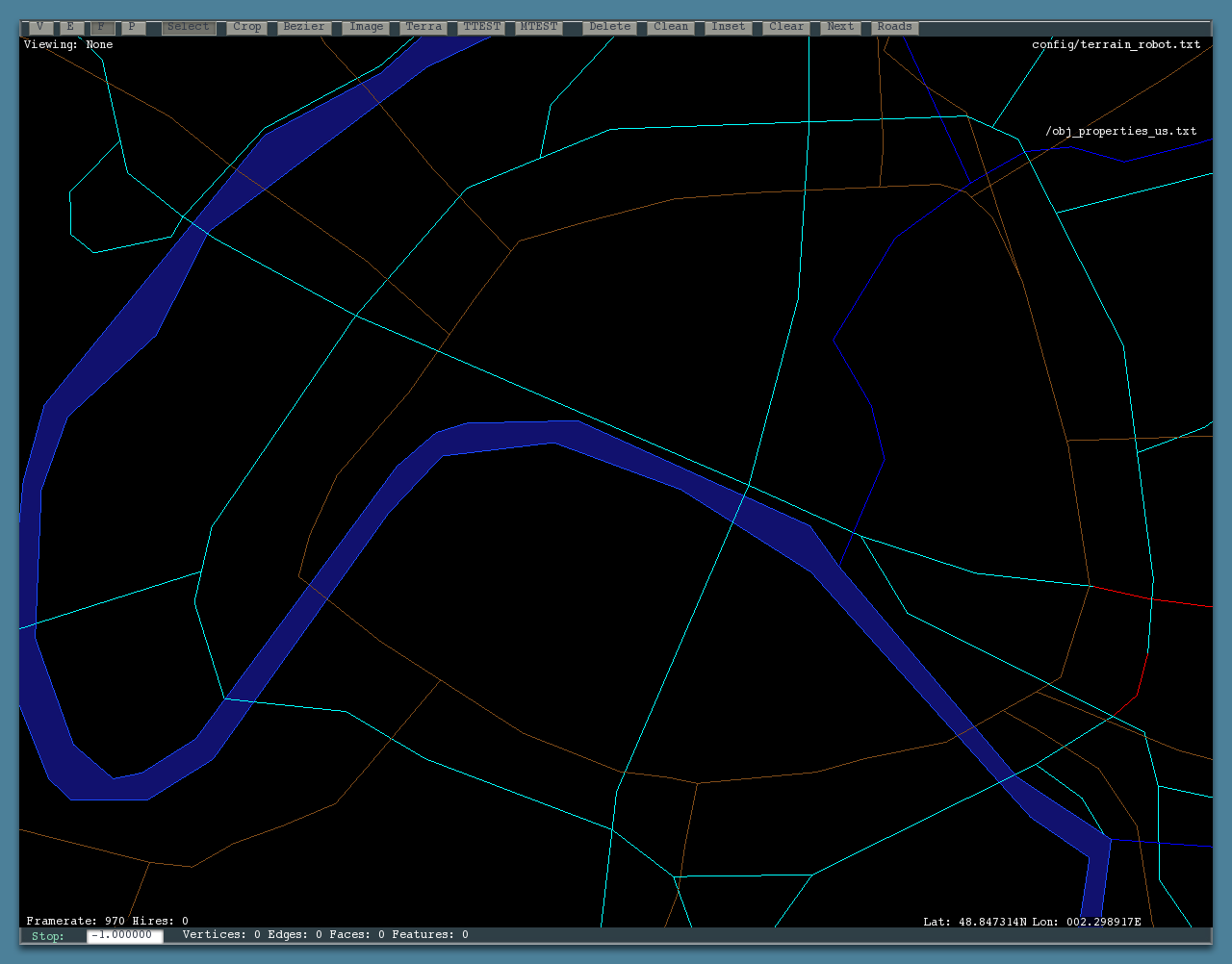
Here is a comparison of downtown Paris in VMAP0 and OSM.
(That’s the 48N 2E tile, which contains Paris. The top images are a whole-tile and metro image from VMAP0, and the bottom are the same areas in OSM.)
There are two big wins with OSM:
- OSM contains significantly better road data in every part of the world. In the US, we had a complete road grid via TIGER, but OSM has been improved to contain direction-of-travel and bridge information. This extra information allows us to construct a much more plausible road system. In Europe the win is incomparable: we are going from having virtually no vector data to having the complete road grid of many major European cities.
- More importantly, OSM provides all of the infrastructure to improve the data. You can directly edit OSM either on your own machine (via JOSM) or directly in your web browser (via Potlatch). OSM has the infrastructure to accept changes, track changes, and the management infrastructure to view history, revert mistakes, and accept many edits from a huge user base simultaneously. Their servers to accept edits are already running and maintained.
I can’t emphasize the importance of this second point enough. In the eight years since I first started poking my nose into X-Plane scenery, I have heard this more times than I can count: “The lake near my house is in the wrong place. Can I fix it and send you the fix”?
Until now the answer has been: no. The lake comes from a data set and when we recut the scenery, any user edits would be destroyed by the conversion from source data. OSM changes that. OSM is the source data, so if you improve global data within OSM, you have fixed the problem permanently.
Not only does OSM make it easy to fix problems permanently, but OSM makes it easy to make very small changes. This morning I was viewing my own town and discovered that two railroad bridges were not marked. I clicked the edit tab, marked out the bridges, and saved my change. You can start with a single edit.
By connecting X-Plane’s source data to the OpenStreetMap community, we can join forces with many other communities that are all working to improve the availability of global mapping data; our improvements (for the sake of improving X-Plane) can help other groups that are working on completely different projects, and their improvements benefit us.
In future posts I will address some of the details of what data we are using, how you can contribute in ways that will affect the global scenery, and how we are (trying) to cope with the OSM licensing change. But I want to make one point immediately:
Just because the global scenery will use OSM does not mean that global scenery will be the only way to use OSM. There are already several existing projects (e.g. XPOSM and OSM2XP) that will build custom scenery from OSM data. OSM provides a rich and detailed geodatabase; the global scenery is only beginning to scratch the surface of what can be done with the data. So I do not see our use of OSM as making some of the other OSM/X-Plane projects obsolete.
For example, OSM2XP utilizes OSM building data, which we will not be using in the version 10 global scenery. I think that the more tools we have to use OSM data, the better, as they give authors more choice in creating scenery.
MeshTool builds a terrain mesh off of two forms of input data:
- Elevation data in raster (2-d array/image) format.
- Vector (linear polygon) format.
Now the density of triangles in X-Plane’s irregular mesh (see here and here for pictures of a typical irregular triangulation) is not related to the DEM density – that is, MeshTool picks and chooses from DEM points to make an irregular mesh with the best DEM points for the budget you specify (via MESH_SPECS). Thus making a bigger DEM does not make a final mesh with more triangles.
The situation with shapefiles and vector data is very different. MeshTool will add as many small triangles as are necessary to guarantee that every line segment in your shapefile’s polygons are represented in the final mesh. That means that if you integrate a shapefile with 1,000,000 line segments, at least 1,000,000 line segments will be “cut into” the triangle mesh.
If you go back and look at those two mesh examples, the second image (lines only, no fill colors) shows this happening: the white vector river at the bottom of the canyon has very short line segments, and the mesh triangles become small to “capture” this detail, even though the underlying elevation is relatively flat (and thus larger triangles would suffice).
Put simply: MeshTool doesn’t reduce the resolution of your vector data, and your vector data directly influences the density of the final mesh. What this means is: if you put a highly detailed shapefile into MeshTool, your final mesh will have a ton of triangles and MeshTool won’t fix it – there are no settings to control the coastline density because MeshTool doesn’t change coastline density. (This even includes silly cases: if you have a coastline that is basically straight but cut into 300 segments, MeshTool will make 300 triangles despite there being no purpose to them.)
This has further implications about your triangle budget. There are only so many triangles you can have in a DSF before MeshTool and X-Plane both start to run out of memory; therefore there is a real cost to having your shapfiles be too dense – your coastlines will take up triangle capacity and you’ll be forced to lower the MESH_SPECS that make the mountains more detailed.
My advice for now: if you can, use an external tool to “simplify” your shapefiles before you input them to MeshTool!
I do hope to address this in MeshTool 1.1 by providing a simplification algorithm in MeshTool itself – we have this code in the scenery tools code base from global-scenery generation, but it didn’t make it into MeshTool 1.0 as a feature.
In my previous two posts I described the problem of Z thrash in some detail, as well as the problems that polygon offset can have in fixing it. I also described how draping addresses these problems. In this post, I will tr to provide some specific rules for how to overlay geometry in your scenery.
Whenever possible ,use draping rather than polygon offset. If your goal is to put a marking on the ground, draping will always do that correctly, while polygon offset can create artifacts if not used properly.
For x-Plane 9, this means preferring draped .pol files to OBJs for putting markings on the ground.
For x-Plane 10, this means using the upcoming ATTR_draped instead of ATTR_poly_os to put markings on the ground.
When you do need to use ATTR_poly_os in an object, you do not need to increase the number – this number is not a layering indication; ATTR_poly_os geometry is drawn in the order it appears in your OBJ. Always have ATTR_poly_os geometry before any 3-d geometry you might want to include.
Finally, if you use ATTR_poly_os, be aware that you’ll want to use a low layer group like markings; if poly-os geometry is drawn after 3-d, you’ll see artifacts.
In my previous post I described Z thrash and how polygon offset is used to fix it. Now we can look at draping and runways.
The fundamental problem with sloped runways is that a runway is made up of tiles, but the ground underneath it may change slopes in unrelated locations. The following diagram illustrates the problem.

This is a side view of a sloped runwy: the green line is the underlying bumpy terrain and the black line is the runway, divided into multiple tiles. Recall from last time that we can only avoid Z-thrash using polygon offset if the two polygons are truly coplanar. Therefore, we can look at four ways to handle the situation and evaluate them for quality:
- In the top picture, the runway simply runs right through the terrain. This case won’t work, with or without polygon offset. In some cases the terrain is on top, and in some cases the runway is on top. The gap between the runway and terrain might be quite large for a significantly sloped runway.
- In the second picture, we move the runway up to clear all but the tallest part of the terrain. This won’t Z-thrash, but it will look pretty bad. There can be a large gap between the runway and the terrain; if you run your airplane off the side of the runway, you’re going to fall. The gap between the runway and terrain will be quite noticeable.
- The third picture is close – each runway tile is clamped to the terrain. But this still isn’t good enough; while most runway tiles now sit on the ground perfectly, a few will take a ‘short cut’ over or under the ground, like the case I have circled in red. So we’ll have less Z thrash, but some parts of the runway will still be broken.
- The last picture is what we really need: we break the runway tiles up into even smaller pieces where the terrain makes a change. The last tile on the right is now two tiles, each of which can sit perfectly on part of the terrain. Only in this last case can we apply polygon offset and get a nice clean runway.
This last case is exactly what X-Plane does. This technique is called draping – the sim ‘drapes’ the overlaid runway tiles on top of the runway like a rug. The sim breaks the tiles into pieces so that each tile can sit perfectly on the underlying terrain.
The real work of draping is not just in figuring out where the terrain below the tile is, it is in cutting the tile into the appropriate pieces that can ‘sit right’. The following pictures show this process in 3-d.
 This is a screen-shot of a small piece of taxiway at KSAN. I have drawn in the outline of the draped polygon in yellow and the terrain triangles in blue. (The terrain triangles are quite large, so we can only see part of them running through the scene.
 This is a wire frame of the problem at hand: we need to insert the yellow polygon into X-Plane, but we need to make sure that no triangles that we generate cross the blue line. The blue lines essentially represent “ridge lines” in the underlying mesh.
 If we just had to draw the yellow polygon, we could triangulate it using the thick gray lines shown in this picture. However, this would not be good; the big gray triangle in the middle of this picture runways right across a blue line – there’s no way that this big gray triangle can “drape” properly across the ridge line.
 This is what actually ends up happening. The gray lines are cuts we need to triangulate the polygon; the red line are cuts we need to not cross the ridge line, and the purple lines are cuts we need to ensure that everything is broken down into triangles (since that’s what the video card really wants). Once we have this triangulation, we can place every vertex on the ground and it will “drape” the way it should.
In my next post I’ll describe how you can use draping in your scenery to create images on the ground without Z thrash.
I think I have mentioned draping repeatedly, as well as Z thrash, without ever clearly explaining what either of these things are. I happen to have some pictures from recent work on draping, so here’s the basic situation.
What Is Thrash?
Warning to OpenGL purists: I’m going to play fast and loose with a number of OpenGL rules. Basically what I say here is the worst case. Sometimes things work out better than I describe, but if you don’t handle the worst case, you’re going to have problems some times. Nitpickers, consider yourself “on notice”.
When drawing 3-d polygons in OpenGL, if two polygons are coplanar, most of the time they will experience “Z thrash” – that is, the hidden surface removal hardware on the graphics card removes some parts of one polygon and some parts of the other, often removing different parts on each frame in a flickering pattern. The results look like this:
 In this picture on the left, we see the raw result of coplanar airport polygons on top of the sandy desert terrain that is the airport surface area. As you can see, the graphics card has been a bit random in deciding whether the runways are “hidden” by the ground or not. If you could see the camera moving, you would see that the pattern of missing taxiways ‘flickers’ as the camera moves.
If there is an overall take-away point so far, it’s this: you can’t just layer coplanar triangles without getting a mess.
(What about moving the runway slightly higher than the pavement? This would have several problems. First, the amount we’d have to move them is horribly dependent on camera angle and video card Z-buffer performance. Second, we’d see the gap between layers; for markings that really do need to be coplanar, like a rubber mark on a taxiway, this would appear as a bug.)
The Cure is Worse Than the Disease
Fortunately if we have truly coplanar geometry, OpenGL gives us a weapon to fight this: polygon offset. Polygon offset is a cheat that tells the video card: “listen, if you ever have doubts about the runway and the ground, favor the runways by a little bit.” It’s a little bit like putting a spread on a football game: the ground would have to be closer than the runway by a margin before we stop seeing.
When we have coplanar geometry, we can use polygon offset to handicap the geometry we want on top. Problem solved, right? So why do I keep writing blog posts with titles like: The Sordid History of ATTR_poly_os or The road to hell is paved with ATTR_poly_os?
Polygon offset has three problems that can bite you:
- The amount of ‘margin’ you get depends on the camera angle. This can make for some truly bizarre effects. The only way to safely manage this is to carefully minimize the margin. (This is a problem for the programmer, not the artist.)
- Because the margin must be minimized, the geometry really has to be coplanar – small cheats can exceed the margin.
- The margin you give your top polygon applies to anything else that is nearby, which can cause even more weird artifacts. For example, if you polygon offset a taxiway, it can start appearing through the nose wheels of airplane. That’s another aspect that must be carefully controlled.
If there’s a take-away to polygon offset, it’s this: polygon offset can help fight Z-thrash, but it must be used in a very narrow set of cases, and it must be used very carefully.
In my next post I’ll describe how X-Plane uses draping to fight Z-thrash for sloped runways.
X-Farm has been canceled. Sorry.
However, there are some new MeshTool builds. Release candidate three fixes a crash on quit on Windows and fixes the SHAPEFILE_MASK command. Builds are here:
Speaking of Mesh scenery: Oahu’s out!
I didn’t think we’d be able to show this, but…
http://www.x-plane.com/blog/wp-content/uploads/2011/04/snout_view2.mov
Yes, X-Farm will have global lighting…
One user asked me about slow performance with an overlay scenery he created using GMaps. There are three things you need for fast orthophotos in X-Plane, and unfortunately his scenery is missing one.
Use DDS
I’ve written before about DDS. They key points here for orthophoto performance are:
- Since DDS is already compressed, the CPU has to do less work preparing the texture if it is going to be compressed.
- Since DDS is already pre-minified (meaning the smaller versions of the texture are already computed), if you are not running at ‘extreme’ resolution, the sim can simply load a lower res version. With png, X-Plane must load the full size version and scale it down on the CPU.
- Since DDS is already pre-minified, the sim doesn’t have to compute those minified versions of the texture on the CPU.
All of these things lead to much faster texture load times with DDS.
Use LOAD_CENTER
LOAD_CENTER is a directive that can be put in a .pol or .ter file to tell X-Plane at what location the texture needs to be at maximum resolution; X-Plane will reduce the resolution of the texture as you fly away from that point. LOAD_CENTER is important for orthophotos for a few reasons:
- It saves VRAM, since textures that are far away won’t be loaded at full resolution.
- When combined with DDS, it improves load time. Since some textures are loaded far away, they can be loaded at lower resolution, which (per above) is quick for a DDS file – less data, less load time.
Note that LOAD_CENTER causes X-Plane to reload the textures while you fly, so it requires at least one extra core to work well. It’s really important to use DDS with LOAD_CENTER; otherwise that reload time can get expensive.
Use a base mesh, not draped .pol overlays.
This is probably the most important thing: if you want to cover a lot of area with orthophotos, you need to rebuild the base mesh using .ter files, not cover it with .pol files. There are a few problems with using .pol files:
- Draped polygons are only ‘built’ for areas relatively near the airplane. So even under ideal circumstances, they are going to disappear in the far view. This way of using them (only when near the airplane) is a memory savings based on their intended use: for small surface areas like airports.
- Similarly, since the draped polygons are being built and destroyed as you fly, the amount of extra CPU work while flying is quite a bit higher with .pol files than with a base mesh (which only has to page the actual terrain). So a computer that might be fine paging .ter files can get behind in its work for .pol files. (Authors often use .pol files because they are easy to work with – specify a rectangle and X-Plane does the cutting and slicing…well, that work is happening while you fly, burning up CPU power that could be used to page the orthophotos.)
- Since .pol files cover the base mesh, you pay for your mesh twice – once when X-Plane draws the base mesh and once when it covers over it with polygons. This means twice the VRAM used to draw a frame and twice the fill rate.
If you want high performance orthophotos over an area any larger than an airport or down-town, please use .ter files!


