(This blog entry explains the background of split beziers – the next parts will explain the bugs that they cause and the workarounds.)
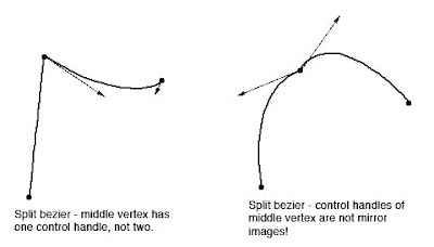
In apt.dat terminology, a split vertex is any vertex of a polygon where the control handles on either side of the vertex are not exact mirror images. (When there is only one control handle it is therefore by definition split!)
You need a split bezier any time you want to:
- Have a sharp corner between two curves and control the tangents of the curves or
- Have a sharp corner between a truly straight segment and control the curve of the next segment.
Split Beziers and apt.adt
Now here’s the rub: the apt.dat format does not allow for split beziers – each curved point has only one control handle – the other is calculated by x-plane by mirroring…thus no vertex can ever be split.
(This is due to a total lack of brains on my part when working on the apt.dat format, which is quite embarrassing considering how long I spent thinking about it.)
The Hack
There is a way to simulate a split bezier: if you use zero-length segments (that is, multiple points on top of each other), you can create a shape that works as if it is split.
In its simplest, a split bezier can be created by using 3 vertices.
- The first vertex uses the control handle of one side.
- The second vertex is not curved.
- The third vertex uses the control handle of the other side.
Why does this work? Well, a bezier curve between a curved point and a straight point has zero length if the two points are on top of each other. So what we’ve done is inserted two zero-length segments. The result of this mess is that the control handles on either “side” of this cluster of points can be different!
Is the second point really necessary! Yes! The reason is this: if we simply had the first and third point (two bezier points with different control handles), X-Plane would draw a loop from the first to the second. Remember: two colocated points with ONE control handle form a zero-length curve, but two colocated points with TWO control handles form a loop.
(To see this for yourself, just draw some examples in WED or photoshop. 🙂
Line Continuity
There is one more wrinkle we have to add to the puzzle in order to understand how this works, and what the pitfalls are: line continuity.
A bezier path (taxiway edge, linear segments, etc.) is made up of one or more bezier curves. Each curve has zero or more attributes.
When X-Plane draws the actual taxi lines and lights, it looks for continuous adjacent bezier curves with the same attribute and makes sure the linkage between those attributes is correct.
(This linkage is computed separately for each type of property. So if you have taxiway lines on two segments and lights on one, the taxiway lines will still link!)
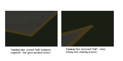
The picture above shows a correct vs. an incorrect link. When dealing with unsplit beziers and non-curved points, linkage is pretty much automatic, it just works.
But there is a pitfall to our above hack for split vertices: we have three points on top of each other. They must all have the same attributes in order for linkage to work. A “break” in the continuity of the line for one of the zero-length segments still counts as a break in linkage. The picture on the right was produced by creating a split bezier and removing the double-yellow-line attribute from the second of three vertices.
In my next post I’ll explain the bugs that this causes in X-Plane 8.60.
An overlay DSF can define exclusion zones – rectangles where scenery from lower priority DSFs is not shown. Exclusion zones are organized by entity type – that is, you must make a separate exclusion zone for objects vs. forests.
The problem with exclusion zones in X-Plane 860 is that the implementation of exclusion zones isn’t quite right for lines and areas.
Essentially any element of a DSF is zero, one or two dimensional:
0d – Points (objects, very small facade objects).
1d – Lines (beaches, roads, large facades with no roofs, bezier lines and bezier object chains).
2d – Areas (large facades with roofs, bezier pavement, forests)
The problem is that X-Plane eliminates any entity if and only if one or more of its vertices intersects an exclusion zone.
This can be wrong in two ways:
– If an entity intersects the exclusion zone, it is deleted entirely, rather than having the exclusion zone subtracted.
– If an entity surrounds or goes through an exclusion zone without a vertex being in the zone, it is left alone.
Every now and then someone sends us this:
http://www.xtremesystems.org/forums/showthread.php?t=117500
The question is of course, why doesn’t X-Plane look like that yet?
Now there’s a lot of reasons why flight simulators don’t look like first person shooters…you can definitely optimize any game content for a specific viewpoint — X-Plane’s lack of constraints on the camera position (you can put the camera quite literally ANYWHERE on the Earth at any time of day, atmospheric condition, and orientation) means that there are going to be views that don’t look so hot. And the global scope of X-Plane means that we have to focus on quantity to a certain extent over quality. (If we made KSBD look totally awesome and didn’t ship any state but California in global scenery, where would we be.)
I’ve been working lately on pixel shaders and lighting…when you look at those shots, the total integration of a number of great lighting effects is responsible for a lot of the look. But…I think there’s a more fundamental issue that pixel shaders and carefully made content wouldn’t address.
Simply put, X-Plane’s LOD system isn’t scalable enough.
In order to get images that look that good you need to put a huge amount of detail up close near the camera, where the user can see it, but not put that detail in the background. (Imagine if every tree in those scenes was done in the detail of the foreground – the polygon count would be unmanageable.)
But X-Plane’s scenery SDK (the interface by which scenery content is specified to X-Plane, in other words, “the file formats”) lacks really strong LOD capabilities.
- The terrain mesh is fixed – you can use LOD to eliminate overlay details, but you can’t actually simplify terrain.
- The cost of LOD in objects is high enough to prohibit really gradual LOD. No morphing is provided.
- Textures are mipmapped but loading is not variable, so our VRAM budget doesn’t benefit from LOD and locality of textures in X-Plane space.
- Generated geometry (roads, trees, etc.) don’t have any LOD except “eliminate whole feature”.
- There is no far view of 3-d clouds.
- Airport layouts are tessolated at only one complexity.
I could go on and on…the bottom line is, X-Plane’s rendering model is very static.
Why did we do that? Well, it seemed like a good idea at the time. In particular, recalculating LOD is very expensive on the CPU and at the time we had only one core. Recalculating LOD would cost more in lost fps than it would benefit in offloading the GPU. So we went for static meshes that we could blast out to the card “real fast”.
What you might not know about those screenshots is what kind of hardware it’s running on:
http://www.gameklip.com/v/1606/
Yep…four cores, and overclocked by over a ghz. (I can only speculate that shortly after the clip ends the machine caught on fire. 🙂 In a multicore environment we can apply additional CPU resources to dynamically rebuild the environment to increase the “LOD range” (difference between the near and far view).
In fact, we already started to do that! In X-Plane 830 we modified the sim to build 3-d content (roads, forests, etc.) on a second core while flying, instantiating only the close ones. This saved RAM and improved the overall performance of the sim, and it increases our LOD range.
(Even if something isn’t drawn, it has a cost just to exist – by saying that things that are really far away don’t even exist we improve performance.)
As you can see from the above list, there’s still a lot to do on the LOD front. But the scenery system is continually growing – new features for the various primitives and improvements to the engine will let us continue to improve sim efficiency.
Something I’m seeing now that WED is in beta: airport layouts with the entire taxiway structure made from one really complex polygon.
I’m not really sure if this is a good idea. First the potential problems:
- I suspect that the creation of the taxiway layouts can get slow when the number of sides in the airport layout is really huge and there are holes. I don’t know this for a fact because we let the OpenGL libraries do the heavy lifting. Because this loading is done on a second CPU, it might not be noticeable to all users.
- The pavement can have only one texture direction per polygon, so multiple polygons may be necessary.
- Certainly in WED having a few large complex polygons slows down editing — if all else is equal, the tools work better with smaller polygons.
Now…overlapping pavement is generally bad (that is, there is a performance cost), but more sides are also expensive. More thoughts:
- The more square feet of overlap, the worse. So a small overlapping intersection is not so bad, but avoid layering a huge polygon on top of another huge polygon, which just strains the video card.
- Fewer segments are better. Consider two crossing taxiways…8 segments with overlap, but 12 by making a plus.
- But wait – the above example is misleading…if you need to change the light types so the blue taxiway lights don’t cross the intersection then you’ll need to add 4 more segments, so now it’s 12 and 12 – a wash. (In this case, having one big polygon is probably easier to manage.)
And for performance…
- Try going to your layout from far away and watch the last step of loading…if it starts to take a long time to “preload” things it means your layout might be a bit complex.
- Do not expect X-Plane to become faster at loading airport layouts…the limiting factors are proportional to complexity, so if you have a killer polygon now it’ll be pretty expensive later too.
One other note, from a conversation with Tom…WED splits vertices into a fixed number of segments (per zoom level) so splitting a bezier makes it smoother. X-Plane does not! X-Plane splits beziers based on the overall curvature, so adding more nodes without changing the shape has no effect.
So please do not try to use the split command to make X-Plane “smoother”. We’ll provide a rendering setting for this some day. The current value was chosen because anything smaller looks awful and you have to make it a lot bigger (read: a lot slower fps) to get an even marginal visual improvement.
Some very advanced users have asked: can we change lights.txt. The answer is: please don’t.
Lights.txt is not a part of the “scenery SDK”, that is, it’s not a file whose format we will keep the same and allow you to modify. (The fact that it isn’t accessible via the library system is an indication of our intention NOT to make it part of the scenery system.)
The problem is basically this: lights.txt translates named lights into the inputs to our pixel shaders for the hardware-accelerated lights. That pixel shader is really new and likely to change a few times. If the shader changes, we might need new parameters not in lights.txt, requiring a fundamental format change.
For example: those who have poked in the named lights file have noticed that the hardware lights can either have directional or flashing properties. This is because they run on two different shaders, each taking only four input values. This was done a while ago, when we were using low level assembly language shaders. In the future we might merge the two shaders and have 8 params per light. This would give us more flexibility (directional flashing lights), more bus usage (pushing 8 params per light instead of 4) and fewer state changes (we have to change shaders right now).
My point is: we can’t predict what will happen, so we can’t safely expose these parameters. The best thing to do is: email me and request named light types. We can easily have hundreds of named-light types (see how many there already are just for airports!).
Named lights make our lives easier because it tells us WHAT to draw but not HOW to draw it. So when we put in the next evolution of the lights code, we can remap the named lights to look the best they can for the new technology, instead of worrying about how to map the old params to the new ones.
(I appreciate the input from the users who emailed me about this — it gives me more insight into what extensions to the scenery system would be useful.)
Any time two independently varying components need to interoperate, a contract is required.
Because X-Plane varies independently of third party add-ons (we release patches, you make new add-ons), any extensible part of X-Plane implies a contract. That contract basically says what legal things the add-on can do and how X-Plane will react.
We have to consider this “contract” with third party add-ons any time we modify the sim, and in some cases it means we can’t change things. How this applies to liveries will become clear later.
Libraries and PNGs
There was some discussion on X-Plane.org about whether it should be possible to share and/or override PNGs via the library system independent of their objects. I say “no” for this reason:
The library system connects independent third party add-ons, that is, components that vary separately. Therefore there needs to be a “contract” any time the library is used, between the package requesting something from the library, and the package fulfilling it.
My concern with PNGs is that a library PNG would have to have a fixed layout. But realistically the kinds of PNGs that people want to share get reorganized on a regular basis. In particular, people want to reference the default sceney PNGs. But where we have a contract, we are limited in what we can change, and reorganizing the default scenery is critical to our ability to grow our content. I agree with Aussie’s comments on x-plane.org that fixed-layout PNGs don’t add a lot of value to the library system.
File System Vs. Text Files
There are a number of design trends in all of X-Plane’s third party add-on systems. One is the use of the file system to specify modifications to the sim. For example:
- Put a “cockpit” folder in your aircraft, we’ll try it first.
- Some files in the aircraft folder must have certain names.
- Sometimes putting _LIT after a texture causes it to be used as a lighting map.
On the other hand, I’ve gone a very different route with the scenery system:
- Libraries are looked up via a text file, not via filename.
- In all scenery cases, the lit texture is specified in a text file, not by filename.
What’s the difference? Well, the file system way seems to be simpler for most users to understand. The text file mechanism is a lot more flexible. (Consider: we have versioning info in a text file, we can have each line in the text file clearly identify a feature, and so there is no risk of a file name being mistaken for a feature.)
Whether we use file names or text files to control extensions, doing so creates a contract, so we must ask: can we easily extend or safely modify the contract later? Can we express what we want using filenames (or text files)?
In the case of the scenery system, I think we need the full expressiveness of text files. Imagine if we wanted to provide a new kind of lighting that uses a different format of texture. Or a way to control at what time of day the lights get turned on? Or what if we want seasonal varying textures, and the rules for how seasons affect the light map aren’t simple? In all of these cases, a file name convention rapidly becomes unworkable.
On the other hand, the airplane system has done reasonably well with filenames. Based on what I see, the problems with airplane distribution mostly come from a lack of features (no livery support, no plugins built into airplanes), not file names as a convention running out of flexibility.
Austin and I were running some numbers on the KSBD demo area DSF as part of a discussion of how instancing will someday allow X-Plane to render more objects. (Instancing is the ability to render multiple simple objects with a single instruction to the GPU…the requirement of one command to the GPU per object means that total object count is bottlenecked by the CPU->GPU connection.)
Here’s some numbers:
KSBD contains 868,220 mesh vertices – at 32 bytes per vertex, we have about 27 MB of geometry per DSF. In one view we picked, about 20% of those vertices were on screen. (But since there are six DSFs loaded, really only about 3% of a DSF mesh is seen at one time at lower altitudes.)
KSBD contains 153,816 objects. Near the airport, we average about 238 vertices per object. (This is a GOOD number – less than 100 vertices would imply that we aren’t sending out enough vertices for each command to draw.) But this means that if we were to simply store all of the objects as one huge object, we would have 1.1 GB of object memory! This is why you can’t just make a single huge object for the world. 🙂
(X-Plane of course stores each OBJ file once, saving a lot of memory. But then we burn CPU power telling each OBJ to be drawn over and over in many places.)
It also explains why forests keep causing people to run out of memory. Consider that only about 3% of the mesh may be visible (when we’re at lower altitudes, where you can see the trees). This means that we need about 30x as much memory to storage geometry as the card can draw. With cards so fast, we easily run out of memory before we max the card out.
Sergio sent me a scenery package with the question: why don’t these two textures appear as the same color in X-Plane (they did in Photoshop). The answer is: gamma correction.
Some background (with much hand-waving): gamma refers to how bright the mid-tones of an image appear. (It’s a lot more complex than that, but that’s what Wikipedia is for!) Basically Macs and some other computers adjust the colors in an image to compensate for the deficiencies of CRTs, while PCs leave them alone. The result is that the same numeric color levels, when sent to Mac and PC hardware, result in brighter images on the Mac than the PC.
Since X-Plane is authored almost entirely on the Mac, the old complaint (around the time of X-Plane 6, with BMPs) was that X-Plane looked too dark on Windows. PNG addresses this issue: the gamma curve of the system an image was created on can be written into the PNG, allowing X-Plane to adjust the colors (making them brighter or darker) depending on what destination system we are running on.
Unfortunately, X-Plane isn’t too brilliant about this, in two ways, one of which isn’t our fault:
- X-Plane assumes the platform default gamma for both Mac and PC (that would be 1.8 for Mac and 2.2 for PC). If you read that background article, you know that this isn’t real clever of us. But it actually is better than doing nothing at all.
- Gamma in PNG files is optional; if we get a PNG file with no gamma information, we make the rather arbitrary assumption that it came from a Mac. Since X-Plane used to be authored on Macs, this seemed like a reasonable thing and in the case of no gamma information, we’re going to be wrong half of the time no matter what.
If you open up the default scenery PNG files in Preview, you can see the gamma inforation – 0.4545. This is 1/2.2, meaning the files are encoded to PC gamma standards. It turns out that one of the textures Sergio sent me had no gamma information, so X-Plane assumed Mac gamma (0.5555, or 1/1.8). Thus the brightness of these textures were being adjusted by different amounts.
My recommendation to authors is simple: make sure that all of your PNG files always have gamma values written into them. Otherwise there is a risk that the default gamma guess that X-Plane makes will not be the one you authored under, causing color shifts.
Ari asked a good question regarding sloped runways and the new apt.dat 850 format:
Am I understanding it right that airport taxiways, ramps and runways are from now on going to be merged into one big mesh, instead of bunch of rectangle pieces overlapping each other? If yes, will this finally allow us turning on sloped runways option in X-Plane without any of the current side effects?
This brings up some interesting questions. First the most basic answer:
- apt.dat 850 prrovides curves, irregular taxiway shapes, which will allow you to create complex taxiway shapes with only one piece of pavement, rather than many overlapping ones.
- X-Plane still honors the order of apt.dat 850 for drawing, so you can also overlap and get visually consistent results.
- We recommend using a smaller number of curved taxiways rather than many overlapping rectangular ones because X-Plane can handles this case more efficiently. It is not necessary to build the entire airport out of one taxiway though.
Now the second part of the second of this question is a little more complex, because the cause of bumps in the scenery changed.
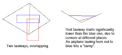
Bumpy Runways in the Good Old Days
Back in X-Plane 806 there was a fundamental problem with the way we did sloped runways that made them virtually unusable: while the corners of each rectangular piece of pavement would sit directly on the terrain (no matter what the terrain’s slope), the area of the taixway was formed by a flat plane. This means that the middle of the taxiway might be above or below the terrain.
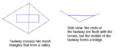
Now the real problem comes when we have two taxiways that overlap. Because they are only aligned to the terrain at their corners and not centers, there may be differences in their height when one taxiway’s corner hits another taxiway’s center (which happens a lot). As the airplane travels from one taxiway to another, the elevation of the ground changes instantly, inducing a major jolt to the suspension. At high speeds these damage the airplane’s suspension.
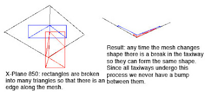
Bumpy Runways Now
In X-Plane 850, we break all runways and taxiways (new and old) into multiple pieces each tiem the terrain underneath them has an edge. The resulting taxiways are then aligned to the mesh at their corners. But since no taxiway center goes over a mesh corner, the taxiway “hugs” the mesh perfectly. And since all taxiways hug the mesh in the same way, there is never a height gap between taxiways.
It’s the Mesh, Stupid
So why do we still have bumps in X-Plane 850 if we so carefully make sure the taxiways exactly reflect the mesh height? Well, you’re effectively driving on the terrain, so any bumps are ones from the terrain. Simply put, even with the new system the usability of sloped runways is only as good as the underlying terrain.
Now our meshes come from SRTM data, which is radar data – it naturally has a certain level of noise and “speckle” which makes it pretty unusable for airports…airplanes are very sensitive to even small bumps during takeoff.
We attempt to “condition” the elevation data for airport use, smoothing out hills and bumps. Unfortunately our algorithm doesn’t always work right. The X-Plane 8 US scenery was way too bumpy to be usable. The 7-DVD set is better, but still makes bumpy airports in a few cases:
- If there was no airport in the apt.dat file at the time of scenery creation, no conditioning was applied, and the underlying terrain is probably inappropriate for draping.
- The scenery creator has a bug that causes airport flattening to fail when it’s very close to water. For example, the big bump in the runway at KLGA is due to a water-airport interaction.
- I think that flattening across DSF tiles can have problems too.
If you’ve been thinking — wow, the diagram for 850 has a lot more triangles (10 vs 4) than the one for 806, you are right. Fortunately, the number of triangles, all part of one taxiway, in an airport layout, doesn’t really affect frame-rate, since this is handled by the GPU.
But this is also a case where a few curved polygons can be much more efficient than several overlapping ones – when we cut up the taxiway based on the mesh, if there is ovelapping pavement, each overlapping taxiway must be cut, multiplying the effects of the mesh on triangle count.
It also turns out that in the real case this is somewhat moot: because X-Plane smooths the airports and then induces triangle borders around the edge of the airport. Since the interior area is so flat, it doesn’t require a lot of triangles, and therefore the trianglse inside an airport tend to be big, so the number of times we have to cut an actual layout is quite small.
A long time ago I posted a picture of my immediate supervisor. I am pleased to announce that the home office has brought on Cecelia to help consult on future X-Plane development. Here she is:
A meeting of the management team: