Tom has a new video on youtube of his just finished Falco. The video shows what screen-shots cannot: that the mouse interactions on the plane are really well crafted.
If you’re just discovering X-Plane (or just discovering that X-Plane’s 3-d cockpits can be very interactive), here’s X-Plane’s “raw” capabilities for manipulation:
- The simplest manipulations are based on mapping the mouse from the 3-d cockpit back to the 2-d panel. This can only be done when the 3-d cockpit is textured using a piece of 2-d panel. This is the oldest way to make a clickable cockpit in X-Plane, dating back to the original X-Plane 3-d cockpits. The advantage of this method is that it’s very easy to set up; the disadvantage is that the mouse click gestures tend to be “flat” in their operation.
- As Tom’s plane demonstrates, you can manipulate just about any dataref or command via a drag along a specific axis. Axes are subject to animation, so there’s a lot of potential for “grabbing” things with this interface.
- X-Plane also supports direct “click” manipulation – this can be handy for buttons where you don’t want to require the user to move the mouse around. There are several types of click manipulation.
Click and drag manipulations can be tied into the plugin system – your plugin sees a manipulation as a change to a plugin-created dataref. This makes it possible to create almost any imaginable mouse effect. If you don’t want to write a plugin, you can still write up the manipulators to any of X-Plane’s datarefs (there are thousands) or commands (we’re getting up toward the 1000 mark on these too).
To create manipulators on your cockpit, you can use the latest plugin for AC3D. A manipulator is a property on a mesh within your object – each mesh can have its own manipulation with its own properties.
X-Plane does not have an IK solver. Rather, movement of “stuff” in your cockpit is indirect.
- Your manipulator changes a dataref as the user drags along an axis.
- The dataref change shows as an animation on your mesh.
Fortunately, ac3d has a “Guess” button for the axis manipulators. If you set a mesh to be manipulated by dragging along an axis, the guess button will examine your animations and suggest an axis that will create the most “natural” looking animation for the manipulation. For example, if you have a throttle handle that rotates, the guess button will provide a drag axis perpendicular to the throttle (to push the levers); if you have a throttle lever that pushes, the guess button will make a drag axis that runs along the lever.
X-Plane 9 has a number of recent features to let you customize the exterior lighting of your aircraft; see the wiki for notes and a sample plane.
X-Plane 940 introduced the concept of parameterized lights to support these features. Here’s the basic idea:
Named lights (available for quite a while now) let you add a light billboard to your model that we define. The idea is that since the lights are specified against a real world model (this light billboard should look roughly like a landing light) it lets us upgrade art assets and back the light with the fastest path on the graphics card.
The problem with landing lights is that they are one-size-fits all, and this is particularly problematic for airplanes, where the lights can look quite different in size and angle based on the size of the airplane. Parameterized lights fix this by letting you specify a limited number of parameters in your OBJ. By limiting the parameters that you can set, it means that we can still optimize the light when possible.
I took a few minutes today to round out the list of parameterized lights, and I think there will be 9.46 patch in which we can release them*. When we put 9.46 in beta I’ll update the example plane; the new set of lights will give you parameterized control over the navigation and taxi lights, as well as the generics, beacons, strobes and landing lights.
* We have a few small bug fixes we’ll roll out in 9.46.
I am trying to be disciplined and put documentation on the X-Plane wiki, and limit the blog to announcements, rants, and explanations of what’s going on inside X-Plane.
You can read about custom lights here. The short of it is that a custom light is a billboard on an object where you (the author) texture the billboard (with part of the object texture), pick the texture coordinates and color, and optionally run all of these parameters through a dataref* that can modify them.
For named lights, the light texture comes from a texture atlas that Sergio made a few years ago – it’s a nice grid 8×8 pretty lights.
So…why can’t you use it with custom lights? Why do custom lights use the object texture?
The answer is: future compatibility. Sergio and I are actually already working on a new texture atlas for the sim’s built-in lights. (This has been a back-burner project for a while … I have no idea when we’ll actually productize this currently experimental work.) What happens when we create a new texture atlas with all of the lights moved around and scrambled? If your object referenced that texture, the texture coordinates would be incorrect.
Thus, for the lights where you specify texture coordinates (custom lights) you use your own texture. For named lights (where the texture coordinate is generated by X-Plane) it’s safe to use ours.
A Dangerous Bug
I found a bug in 940 that’s been in the sim for a while now: given the right strange combination of named and custom lights in a row, the sim would accidentally use Sergio’s texture atlas rather than the object’s texture for custom lights.
This is a mistake, a bug, and it will be fixed in the next 941 release candidate. I certainly hope there aren’t any objects out there relying on this erroneous behavior, which violates the OBJ spec and is pretty dangerous from a future compatibility standpoint.
* Dataresfs are normally thought of as data we read, so the idea of using them to “process” data is a bit of a bastardization of the original abstraction. You can read about the dataref scheme in detail here.
X-Plane 940 has these generic light things…what the heck are they? Here’s the story:
X-Plane has been growing a larger number of independently simulated landing lights with each patch. We started with one, then four, now we’re up to sixteen. Basically each landing light is a set of datarefs that the systems code monitors.
- You use a generic instrument to hook a panel switch up to a landing light dataref.
- The sim takes care of matching the landing light brightness with the switch depending on the electrical system status.
- Named lights can be used to visualize the landing lights.
See here for more info.
But what else lights up on an airplane? Sergio sent me the exterior lighting diagram for an MD-82, and it would make a Christmas tree blush. There are lights for the staircases, for the inlets, on the wings, pointing at the wings, the logo lights, the list goes on.
We have sixteen landing lights, so we could probably “borrow” a few to make inlet lights, logo lights, etc. But if we do that, the landing light will light up the runway when we turn on any of those other random lights.
Thus, generic lights were born. A generic light is a light on the plane that can be used for any purpose you want. They aren’t destined for a specific function like the strobes and nav lights. There are 64 of them, so divide them up and use them how you want. Just like landing lights, you use a generic light by:
- Using a generic instrument to control its “switch” from the panel.
- Using a named light to visualize it somewhere on the OBJs attached to your airplane.
Generic lights don’t cast any light on any other part of the plane – sorry. You can use ATTR_lit_level to light up part of your mesh dynamically when the generic light comes on though – the effect can be convincing if carefully authored.
Normally I try to make the X-Plane scenery and modeling system as opaque as possible — I want to make sure that nobody ever actually uses the rendering features that I spend weeks and weeks developing.
But the other night I had a little bit too much to drink, got distracted, and posted these:
In all seriousness, I have been trying to find time to put more documentation up on the Wiki. For these features, you will find an explanation of how the planes work, as well as a link to the planes (with plugins) to download, and a link to the plugin source code (on the SDK site, with sample makefiles for 3 operating systems).
Plugins? Do not panic! While plugins are necessary for some of the features demonstrated here, others can be created without additional programming.
BTW, if the existing documentation uses a concept that is not explained anywhere, please email me. I sometimes leave holes in the documentation by accident.
Well, I won’t stop you from lying to X-Plane, but if you do, your add-on may have problems in the future.
Basically: some parts of X-Plane take measurements of real world information and attempt to simulate them. I have previously referred to this as “reality-based” simulation (e.g. the goal is to match real world quantities).
In those situations, if you intentionally fudge the values to get a particular behavior on this particular current version of X-Plane, it’s quite possible that the fudge will make things worse, not better in the future.
This came up on the dev list with the discussion of inside vs. outside lighting. X-Plane 9 gives you 3 global lights for objects in the aircraft marked “interior”, but none for the exterior.
Now there is a simple trick if you want global lights on the exterior: mark your exterior fuselage as “interior” and use the lights.
The problem is: you’ve misled X-Plane. The sim now thinks your fuselage is part of the inside of the plane.
This might seem okay now, but in the future X-Plane’s way of drawing the interior and exterior of the plane might change. If it does, the mislabeled parts could create artifacts.
So as a developer you have a trade-off:
- Tweak the sim to maximize the quality of your add-on now, but risk having to update it later.
- Use only the official capabilities of the sim now, and have your add-on work without modification later.
Javier posted a video of his CRJ on the dev list today. I have not tried the plane, but there is no question from the video that it looks really good. What makes the video look so nice is the careful management of light. Part of this comes from careful modeling in 3-d, and part of it comes from maxing out all of X-Plane’s options for light.
But…what are the options for light on an airplane? I don’t know what Javier has done in this case, but I can give you a laundry list of ways to get lighting effects into X-Plane.
Model In 3-D
To really have convincing light, the first thing you have to do is model in 3-d. There is no substitute – for lighting to look convincing, X-Plane needs to know the true shape of the exterior and interior of the plane, so that all light sources are directionally correct. X-Plane has a very large capacity for OBJ triangles, so when working in a tight space like the cockpit, use them wisely and the cockpit will look good under a range of conditions.
You can augment this with normal maps in 940. Normal maps may or may not be useful for bumpiness, but they also allow you to control the shininess on a per-pixel basis. By carefully controlling the shininess of various surfaces in synchronization with the base texture, you can get specular hilights where they are expected.
The 2-D Panel
First, if you want good lighting, you need to use panel regions. When you use a panel texture in a 3-d cockpit with ATTR_cockpit, X-Plane simply provides a texture that exactly matches the 2-d cockpit. Since the lighting on the 2-d cockpit is not directional, this is going to look wrong.
When you use ATTR_cockpit_region, X-Plane uses new next-gen lighting calculations, and builds a daytime panel texture and a separate emissive panel texture. These are combined taking into account all 3-d lighting (the sun and cockpit interior lights – see below). The result will be correct lighting in all cases.
Even if you don’t need more than one region and havea simple 1024×1024 or 2048×1024 3-d panel, use ATTR_cockpit_region – you’ll need it for high quality lighting.
The 2-d panel provides a shadow map and gray-scale illumination masks. Don’t use them for 3-d work! The 2-d “global lighting” masks are designed for the 2-d case only. They are optimized to run on minimal hardware. They don’t provide the fidelity for high quality 3-d lighting – they can have artifacts with overlays, there is latency in applying them, and they eat VRAM like you wouldn’t believe. I strongly recommend against using them as a source of lighting for a 3-d cockpit.
To put this another way, you really want to have all global illumination effects be applied “in 3-d”, so that the relative position of 3-d surfaces is taken into account. You can’t do this with the 2d masks.
The 2-d panel lets you specify a lighting model for every overlay of every instrument – either:
- “Mechanical” or “Swapped” – this basically means the instrument provides no light of its own – it just reflects light from external sources.
- “Back-Lit” or “Additive” – this means the instrument has two textures. The non-lit texture reflects external light, and the lit texture glows on its own.
- “Glass” – the instrument is strictly emissive.
You can use 2-d overlays not only for instruments but also to create the lighting effect within instruments, e.g. the back-lighting on a steam gauge’s markings, or the back-lighting on traced labels for an overhead panel.
2-d overlays take their lighting levels from one of sixteen “instrument brightness” rheostats. You can carefully allocate these 16 rheostats to provide independent lighting for various parts of the panel.
The 3-d Cockpit
The 3-d cockpit allows you to specify 3 omni or directional lights. These can be placed anywhere in the plane, affect all interior objects, and can be tinted and controlled by any dataref. Use them carefully – what they give you is a real sense of “depth”. In particular, the 3-d lights are applied after animation. If a part of the cockpit moves from outside the light to into the light, the moving mesh will correctly change illumination. This is something you cannot do with pre-baked lighting (e.g. a _LIT texture).
Finally, ATTR_light_level is the secret weapon of lighting. ATTR_light_level lets you manually control the brightness of _LIT texture for a given submesh within an OBJ. There are a lot of tricks you can do with this:
- If you know how to pre-render lighting, you can pre-render the glow from a light onto your object into your _LIT texture, and then tie the brightness of the _LIT texture to a dataref. The result will be the appearance of a glow on your 3-d mesh as the light brightens. Because the lighting effect is pre-calculated, you can render an effect that is very high quality.
- You can create back-lit instruments in 3-d and link the _LIT texture to an instrument brightness knob.
- You can create illumination effects on the aircraft fuselage and tie them to the brightness of a beacon or strobe.
There are two limitations of ATTR_light_level to be aware of:
- Any given triangle in your mesh can only be part of a single ATTR_light_level group. So you can’t have multiple lighting effects on the same part of a mesh. Plan your mesh carefully to avoid conflicts. (Example: you can’t have a glow on the tail that is white for strobes and red for beacons – you can only bake one glow into your _LIT texture.)
- ATTR_light_level is not available on the panel texture. For the panel texture, use instrument brightness to control the brightness of the various instruments.
I have a sample plane that demonstrate a few of these tricks; I will try to post it on the wiki over the next few days.
Yesterday I blogged about Order Independent Transparency (OIT). That robot is very shiny, but what does this fix in X-Plane itself? Here are two pictures that show the problem in an X-Plane context.
This is the Cirrus jet in X-Plane 9.22.
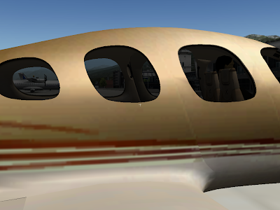
Pretty, eh? But…look through the right two windows – look at the passenger door on the other side. Note that through the middle window the passenger door is visible. Through the right window, the entire passenger door is gone!
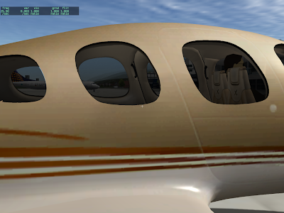
This is the same shot from X-Plane 940, where the problem has been corrected.
The bug you see here is incorrect draw order. In X-Plane 922, the right door (which contains the right-most near window) is drawn before the left door – hence its translucent part destroys the door.
Max fixed this by changing the draw order of the model – the new cirrus draws the inside view of both doors before the outside view of either doors; because the geometry is one-sided he can draw the ‘inside’ first and outside ‘second’.
These two
blog posts explain translucency in a lot more detail.
What X-Plane has now is “order dependent” transparency – if translucent surfaces are not drawn from far to near, you get artifacts like the missing door.
What OIT promises (and that robot demonstrates) is the ability to have translucent geometry and not have the objects behind the translucent parts disappear.
If you have ever textured an airplane, then you know that you can’t use the same texture for both sides of the plane if there is writing on the fuselage. The writing will be horizontally mirrored on one side.
The same thing goes for normal maps – you can’t mirror a normal map without getting bogus results. Think of your normal map as a real 3-d (slightly extruded) piece of metal. If you are seeing the text go the wrong way, the metal must be facing with the exterior side pointing to the interior of the airplane.
Having your normal map flipped does more than just “inset” what should be “extruded” – it completely hoses the lighting calculations. In some cases this will be obvious (no shiny where there should be shiny) but in others you will see shine when the sun is in a slightly wrong position.
The moral of the story is: you can’t recycle your textures by flipping if you want to use normal maps.
The rule is very simple: if you want to put a marking on the ground, your results will be much better if you use a .pol (draped polygon) or .lin (draped line) than if you use an OBJ. In fact, an OBJ is probably the worst way to put markings on the ground.
Requirements for Good Looking Markings
In order for markings to look good you need to have three things happen:
- You need to make sure your markings are at the exact same level as the ground itself.
- You need to use polygon offset to tell X-Plane to tell the video card that these are “coplanar” (at the same height) triangles that must be managed in a special way.
- You must guarantee that the draw order is: the stuff under your markings, your markings, then the 3-d buildings and other 3-d stuff.
With these requirements we can compare .pol/.lin files to OBJs:
- .pol and .lin files always “drape” to the ground, so they always meet rule 1 perfectly. With an OBJ you can set the height of your OBJ to 0 but on sloped terrain this won’t be correct.
- .lin and .pol files are always “polygon offset” automatically, so they always meet rule 2 perfectly. With an OBJ you need to use ATTR_poly_os.
- ATTR_layer_group (or LAYER_GROUP) tell the OBJ or pol/lin in what order to draw, so you can set this correctly in all cases. The default values if you don’t specify a layer group are more appropriate to the task of markings on the ground when you use a pol/lin – that is, by default they meet rule 3 perfectly. By comparison, an OBJ may not be in the right draw order.
So we can see from these 3 rules that you will always get the rules right just by using a pol or lin, but you have to be very careful and may still not get the rules right when using an OBJ.
Performance? Think .pol
When you have a large number of small markings, the performance of a .pol is going to be significantly superior to the performance of an OBJ. For example, imagine an airport where you want to draw on-pavement signs for all taxiways and runways. With an OBJ, to get the height right, you’d need to use a large number of small objects. (With one large object, it will be nearly impossible to make the OBJ markings be on the ground when far from the object center.)
When you use a large number of .pol markings that share one common texture and all have the same .pol file, X-Plane merges them behind the scene into one huge object-like pile of triangles. The cost of drawing all of those polygons will be similar to the cost of drawing just one object! That’s a huge speed win.
Floating Objects Are Wrong
What I see most commonly in scenery packs that are sent to me and have thrashing problems are OBJs that have a height other than 0. This is simply the wrong way to create overlaid geometry in X-Plane, and it will produce artifacts in a wide variety of situations. At best, the “floating” objects will cause airplanes driving over the marking to look like they “sink in”. At worst, the offset you pick will be too small for the video card’s resolution and you’ll get thrash anyway.
There is no one right vertical offset for all scenarios, and even if there was, it would still look ugly! See the above rules for what an OBJ really has to do.
How Do I Get a .pol into my scenery.
Well that is the $10,000 question. I must admit that I don’t know what Overlay Editor’s capabilities are in this regard. WED 1.1 will be able to add draped polygons, including texture coordinate editing of the polygons. I’ve been working on the texture coordinate editor in WED this weekend and am hoping to get some kind of WED 1.1 preview built this week.
With WED 1.1 the process is fairly simple:
- Create your texture.
- Create a single .pol text file that names the texture, so you can use it.
- In WED 1.1 you can select the .pol from the list of resources for your scenery pack, and then use the “polygon create tool” to simply draw the draped polygons into place.
- Once the draped polygons are created, you can select the polygon and open the “texture coordinate editor” tab to edit the way the texture is applied to the polygon.
My hope is that this process will be easier than creating markings using a 3-d editor – you can still edit the texture coordinates, but you can do so directly in WED.

