Realistic AI aircraft traffic at airports requires specifying multiple parameters in the WED scenery file.
Thoughhout all version of X-Plane 11, minimum requirements for successful AI traffic operation at an airport are:
The airport is of type “airport”, i.e. not a “seaport” or “heliport.”
Have at least one ATC frequency of type “Tower” defined.
Note this refers to the “Type” property, not the name given to the frequency entry, which has no relevance for AI operation.
At least one (very preferably multiple) ramp starts of sufficient size is specified:
The size of the largest ramp start (of any type) must be larger or equal to the actual AI aircraft attempting to spawn/land.
X-Plane will not check if that ramp start is actually vacant or the right type – it rather gives ATC authority to make “emergency” decisions like parking a 747 on a Size A “Props” “Misc” ramp start, if none of the size F starts at that airport are available for some reason.
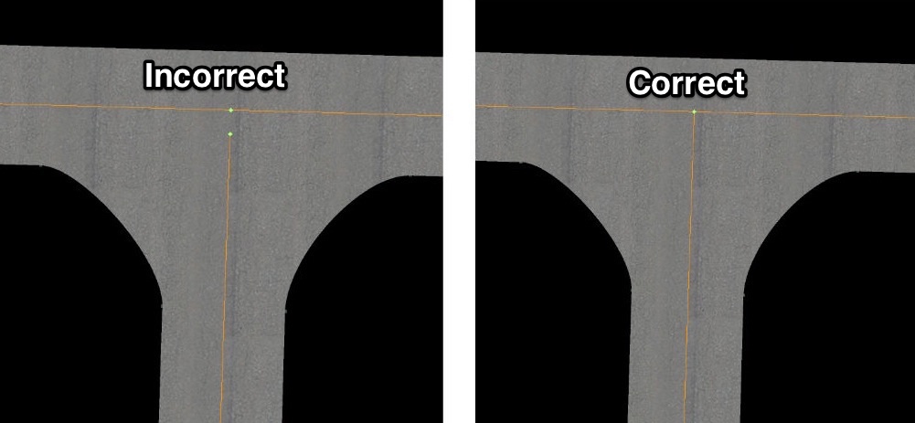
The airport should have at least one ramp start of type “gate/tiedown” and all starts near the runway should be of type ”misc” only. This prevents ATC accidentally spawning AI inside a runway hotzone – which creates a fatal deadlock.
At least one paved runway (surface = “Asphalt” or “Concrete” only) of sufficient width and length is active.
Active means either
there is valid flow specification that meets the current weather condition and it includes a “Runway use” rule for that runway
or no flows are specified. In this case, X-plane will auto-generate suitable flows that activate all runways under any weather condition.
Sufficient width & length depends on the AI aircraft category as in the table below:
Aircraft category
Min. Rwy Width
Min. Rwy Length
Heavy
125 feet
10,000 feet
Fighters
125 feet
7,500 feet
Jets
100 feet
7,500 feet
Turboprops
75 feet
2,500 feet
Props
50 feet
2,500 feet
Anything else
25 feet
1,000 feet
These are all conditions to make AI spawn or attempt to land at the airport.
Note: In older documents – the “has ATC” property was noted as required for AI use. Since X-Plane 10 it is actually officially ignored – so it’s not required. Some airports may even have AI and ATC functionally without an ATC tower frequency defined in WED/apt.dat – if there is a (very rarely) used option to define ATC tower frequencies in an atc.dat file to accompany the scenery.
It also implies the actual ramp start types and ATC taxi network details do not prevent AI operation, but only help to make it look more “plausible” once AI are present at the airport. A working ATC Taxi network, either auto-generated by X-plane or specified in the scenery is required to have those AI successfully leave the runway and taxi to/from the ramp starts.
Troubleshooting Tips
To debug problems with AI operations it is recommended to start with hiding all user specified flows and ATC taxi networks in the WED scenery pack. X-Plane will then auto-generate these items, which will result in functional flows & networks, although they will also appear less polished.
By default, the X-Plane log.txt also includes information about AI spawning, flow selection and AI Taxi instructions. The art control atc/debug/log_spawn=1 prints log info on AI aircraft arrival & departure logic. Use the developer console to see this in-sim or view it in the log.txt
Note: This article is for plugin developers. If you’re a user just trying to install a plugin, please see the “Expanding X-Plane” section of the X-Plane manual. (The exact method of installation depends on the plugin, but for many plugins, you can simply drop the plugin directory into your Resources\plugins\ directory.)
Platform Choices & Decisions
X-Plane supports plugins for all three operating systems (macOS, Windows, and Linux). This article covers issues of building and packaging plugins.
Which API to Use
There are three revisions of the X-Plane plugin API:
1.0 API is supported by X-Plane 6.70 and newer.
2.0 API is supported by X-Plane 9.00 and newer, is a superset of the 1.0 API
2.1 API is supported by X-Plane 10.00 and newer, is a superset of the 2.0 API
3.0 API is supported by X-Plane 11.10 and newer, is a superset of the 2.1 API
Plugins are almost the same for all APIs; a few exceptions for compiling and linking 2.0+ plugins will be noted.
You can use the latest SDK download to build your plugin no matter what version of the API you are targeting. By default your plugin will only be able to use 1.0 APIs and run on any version of X-Plane.
If you define the symbol XPLM200, then the 2.0 API will be available to your code, and your plugin will only work on X-Plane 9 and later.
Likewise, if you define the symbol XPLM210, you’ll have access to the 2.1 API and your plugin will only work on X-Plane 10 and newer.
Finally, if you define the symbol XPLM300, you’ll get access to the 3.0 API, and your plugin will work X-Plane 11.10 and newer.
If you’re just starting out, we recommend using the SDK 3.0 API and defining XPLM200, XPLM210, and XPLM300.
If you’re building a backward-compatible plugin (say, for both X-Plane 10 and 11), you can link against the 2.0 API and use the XPLMFindSymbol() utility to optionally fetch newer APIs. If they are not present, your plugin will receive a NULL return value and can take a fallback path.
Plugin Containers
Plugins are DLLs (dynamically linked libraries). While these have different names on different operating systems, the concept is the same: code that is linked into X-Plane while it is running. We will use the term DLL generically to mean a shared library of the appropriate type for your chosen ABI. The container types are:
DLLs (.dll) for Windows
Shared Objects (.so) for Linux
Shared Dynamic Libraries (.dylib) for macOS
Note that in all of these cases the plugin’s extension is .xpl, as dictated by SDK conventions, not the native platform.
Packaging Thin Plugins
A “thin” plugin is the original way of packaging plugins: the plugin consists of a single DLL with the extension .xpl, which is dropped into X-Plane’s Resources\plugins\ directory. All auxiliary files (image files, etc.) must be kept outside the plugin. Thin plugins are the only packaging supported by the 1.0 API. (Originally thin plugins were just called “plugins”.)
The obvious downsides of this are that you have to distribute a different plugin for each operating system, and you don’t get a plugin “home” directory to pack your resources.
In order to build a thin plugin, make sure your plugin ends in the extension “.xpl”.
Packaging Fat Plugins (XPLM 2.0 API)
A “fat” plugin is a folder containing one or more plugins. The plugins inside the folder have the specific names win.xpl, mac.xpl and lin.xpl. A fat plugin provides a container format that is portable across multiple operating systems; X-Plane loads only the plugin that is appropriate for the host computer and ignores the rest. The folder can also contain support files, allowing the user to install the plugin by dragging a single folder.
Fat plugins require the 2.0 API, and are the recommended way of packaging plugins that would require the 2.0 API or X-Plane 9 for other reasons.
To build a fat plugin, make sure the actual binary is inside a folder (which in turn is inside the plugins folder) and that the binary is named win.xpl for Windows, mac.xpl for OS X, or lin.xpl for Linux.
The recommended layout for a fat plugin is:
plugin folder
 mac.xpl <- mac dylib with multiple code architectures: ppc, i386, x86_64
 32
 win.xpl <- 32-bit (win32) windows dll
 lin.xpl <- 32-bit (i386) Linux shared object
 optional other 32-bit dlls needed
 64
 win.xpl <- 64-bit (x64) windows dll
 lin.xpl <- 64-bit (x86_64) Linux shared object
 optional other 64-bit dlls needed
 other files for the plugin (pngs, etc.) in any sub folders as desired.
Packaging Fat Plugins (XPLM 2.1 API)
New in X-Plane 10 are the 32-bit and 64-bit variants of fat plugins. In this case, the plugin packaging looks like this:
my_plugin/
64/
mac.xpl
win.xpl
lin.xpl
32/
mac.xpl
win.xpl
lin.xpl
(Note that you don’t need to ship both 32- and 64-bit variants of your plugins to use this packaging.)
Packaging Fat Plugins (XPLM 3.0 API)
As of X-Plane 11.10, we support one more format for packaging plugins. The downside to the 2.1 format is that all plugins are named [platform].xpl, which makes debugging tools hard, if not impossible, to use with shipping plugins. (They assume that all DLLs will have unique names, and therefore get confused if you have multiple plugins loaded that are both called, e.g., win.xpl.)
For that reason, as of XPLM 3.0, you can package plugins like this:
my_plugin/
mac_x64/
my_plugin.xpl
win_x64/
my_plugin.xpl
lin_x64/
my_plugin.xpl
(Note, of course, that X-Plane 11 supports only 64-bit plugins.)
Global, Aircraft, or Scenery Plugin
A “global” plugin is one that is installed in the Resources\plugins\ folder. This is the original way to install a plugin and the only one supported by the 1.0 SDK. Global plugins must be installed directly into the plugins folder (which is in turn inside the Resources folder); sub-folders are not examined.
The 2.0 API also allows plugins to be stored with aircraft; such aircraft-based plugins are loaded when the user loads the plane (not counting multi-player use of the plane) and unloads the plugin when the user picks another aircraft.
The 2.1 API also allows plugins to be stored with a scenery pack; such scenery-based plugins are loaded at startup with the global plugins, so be sure to keep resource use to zero when the user is not in your scenery area.
Only fat plugins can be stored with an aircraft or scenery pack. An aircraft plugin goes in a “plugins” folder that in turn is inside the root folder of your aircraft package. A scenery plugin goes into a “plugins” folder that in turn is inside the root folder of your scenery package.
Compiling Plugins
This section describes some of the issues when compiling plugins. This document is not meant to be substitute for the original documentation for your development tools, nor is it meant to be instructional in this regard. You should be able to use your chosen tool set to build DLLs before you begin writing plugins.
The simplest way to compile your plugins is to start with one of the examples, which come with project files and perform all the setup described below.
Recommended Compilers
We do not recommend any particular compiler, but there are more SDK-related resources available for the compilers used to produce the basic examples. Those compilers are:
macOS: LLVM (via Xcode)
Windows: Visual Studio 2010 Express or Visual Studio 2015
Linux: GCC 4.x
The sample code provides templates that support these compilers. One way to get started is to download a sample and then replace the code while keeping the project.
Setting Up Defined Macros
In order to use the X-Plane SDK headers, you must pre-define some macros before including any SDK headers. This is usually done by setting up the definitions (a.k.a. preprocessor macros) in your compiler settings. Most compilers accept the command-line option -D<symbol>=<value>; Xcode and Visual Studio both have project settings to predefine symbols, and in both cases they result in -D command-line options being sent to the compiler.
You must define one of the macros APL, IBM, or LIN to 1, depending on the OS you are compiling for. If no platform is defined, you will get a “platform not defined” compile error as soon as you include any SDK headers. Typically you would define the platform in the project settings or make file for each platform, so that the code can be shared between all three without modification.
Macros for the 2.0 and newer SDK APIs
In order to use the 2.0 APIs, you’ll need to define the symbol XPLM200. To the the 2.1 APIs, you’ll need to also define XPLM210, and for the 3.0 APIs, you’ll need to define all three of XPLM200, XPLM210, and XPLM300.
(This feature is designed to let you build plugins that link against old versions of the SDK from the same SDK headers. If newer symbols are not defined, you cannot accidentally use a newer routine.)
Including the SDK Headers
To use X-Plane SDK functionality, you must include the SDK headers, like this:
In order for this to work, you must tell your compiler where to locate the header files. You must first decide where to install the header files. There are two basic choices:
If you work on your projects by yourself, you can pick one location on your hard drive to place the SDK and use it for all of your projects. The advantage is you will only have one copy of the SDK to update in the future.
If you share your projects with other developers, it is important that the SDK location be the same for all developers, and be located relative to the project. (Otherwise all developers would need the same hard drive name.) In this case, it makes sense to copy the SDK headers and libraries into the source tree of each project.
Once you have decided on an install location, you must provide your installer with an include path that tells it where the headers are. For example,
-IXPSDK/CHeaders/XPLM
-IXPSDK/CHeaders/XPWidgets
Most compilers require one include path for each directory to be searched.
OpenGL Considerations
OpenGL is not part of the SDK, but it is the main API for drawing from plugins, so you will almost certainly need it to create any kind of custom graphics. OpenGL deployment varies a bit by platform.
On macOS, OpenGL is a framework, and it is always available. Using OpenGL requires two steps:
Add the framework to your project in Xcode (or use -framework OpenGL on the command line).
Include the headers like this:
#include <OpenGL/gl.h>
For Windows and Linux, include OpenGL like this:
#include <GL/gl.h>
On Linux, you may have to first install a package, e.g.:
sudo apt-get install freeglut3-dev
(Specific instructions for your distro may vary.)
DLL Attach Functions for Windows
Windows requires a “DLLMain” function to be included in your code. It is essentially boilerplate, and typically doesn’t have to do any useful work. Here is a sample DLLMain function:
#if IBM
#include <windows.h>
BOOL APIENTRY DllMain( HANDLE hModule,
 DWORD ul_reason_for_call,
 LPVOID lpReserved
 )
{
 switch (ul_reason_for_call)
 {
 case DLL_PROCESS_ATTACH:
 case DLL_THREAD_ATTACH:
 case DLL_THREAD_DETACH:
 case DLL_PROCESS_DETACH:
 break;
 }
 return TRUE;
}
#endif
Symbol Visibility (GCC4 or higher)
For GCC-based environments (command-line Linux), the default behavior is to export all non-static C functions out of your plugin. This is not what you want, and can cause serious compatibility problems for 32-bit plugins. To get around this, use
-fvisibility=hidden
on your compiling command line.
The macro PLUGIN_API (defined by XPLMDefs.h) automatically marks a symbol as exported, so yo can do this:
PLUGIN_API void XPluginStop() { /* ... */ }
and your plugin will work correctly.
Linking Plugins
Linking is the process of taking your compiled code and making an actual DLL file on disk that is your plugin.
Linking on Windows
You will need to link against XPLM.lib, found in the SDK under SDK/Libraries/Win. Link against:
If you are using OpenGL, you’ll also want to link against OpenGL32.lib.
We recommend you set all MSVC settings to avoid depending on external DLLs other than the CRT runtime; these DLLs may not be present on destination machines, and can cause your plugin load to fail. Linking the CRT runtime statically however will cause problems for users who have a lot of plugins installed and run out of TLS slots when loading plugins.
C++ Code Generation: set the runtime to “multi-threaded DLL”, not “multi-threaded.”
General: do not use common language runtime support or MFC.
Linking on macOS
You will need to add XPLM.framework and XPWidgets.framework from the SDK to your plugin; you may also need to add the system frameworks OpenGL and possibly System or CoreFoundation to your plugin depending on what Mac settings you use.
Do not use the options “-undefined_warning” or “-flat_namespace” – these are no longer needed and not recommended.
Linking on Linux
There are no link libraries on Linux for the SDK; instead pass the command-line option
A plugin is executable code that runs inside X-Plane, extending what X-Plane does. Plugins are modular, allowing developers to extend the simulator without having to have the source code to the simulator. This article describes the basics of what a plugin is, how it works, and describes how we write one.
If you are an experienced programmer, you may already be familiar with some of the material presented here. If you have not done modular programming using DLLs, we introduce the concepts and also provide step-by-step examples of writing a very basic plugin.
What a Plugin is and What Plugins Can Do
Before discussing how to write a plugin, we will describe to some extent what it can do. You may not need a plugin for what you are trying to accomplish, and a plugin may not be able to accomplish what you are trying to do.
Plugins are executable code that are run inside X-Plane. Plugins allow you to extend the flight simulator’s capabilities or to gain access to the simulator’s data. Plugins are different from conventional programs in that they are not complete programs in themselves, but rather program fragments that get added to X-Plane while it runs. Because plugins run “inside” the simulator, they can accomplish things that a standalone program might not be able to. But since plugins are not full programs, they have limitations that normal programs do not.
Plugins can:
Run code from inside the simulator, either continually (for example, once per flight cycle) or in response to events inside the simulator. For example, a plugin can run constantly inside the simulator and log data to a file.
Read data from the simulator. For example, a plugin can continually read the values of the flight instruments and send them over the network.
Modify data in the simulator, changing its actions or behavior. For example, a plugin can change the aircraft’s position, or replace the simulator’s flight model entirely.
Create user interface inside the sim. For example, a plugin can create popup windows with instruments or dialog boxes.
Control various subsystems of the simulator. (These APIs are discussed in more detail below.)
Some parts of the simulator are controlled simply by writing data to the simulator. For example, to set the elevation of the cloud bases, we simply set that variable in the sim. Other subsystems require more complex interaction and have specific APIs. For example, there is an API to program the simulator’s Flight Management System.
Plugins and DLLs
Plugins are DLLs; an understanding of DLLs is necessary to understand how plugins work.
About DLLs
A dynamically linked library (DLL) is a set of compiled functions or procedures and their associated variables. DLLs are different from normal programs in a few key ways. A DLL does not contain a “main” function that is run once to run the entire program. Instead the DLL contains lots of functions, and another program uses the DLL by calling these functions.
A DLL contains a directory of the functions inside. Other applications can read that directory to find the function they are looking for. The functions in this directory are known as the exported functions because the DLL is said to “export” them to other programs. Not all of the functions in the DLL are exported; functions that are not exported are said to be internal. A program can only directly call the exported functions in a DLL, because it must find these functions through the directory. But the exported functions in the DLL can then call the internal functions.
DLLs are powerful because the program that uses the DLL finds and runs the code in the DLL when it is executed, not when it is compiled. Consider the case of a set of math functions for a calculator. If we simply compile the math functions into our program, then when we change the math programs (for example, to make them faster or more accurate), we have to recompile our whole program. If we know that the math functions are likely to change, we can put them into a DLL and have the calculator program find these functions when it runs. Since the calculator finds the math functions every time it runs, we can create a new DLL with the same function names but better implementations and substitute it for the old DLL. The calculator function will not care as long as the functions have the same names and take the same inputs. This allows us to upgrade or change the behavior of our calculator program without recompiling it.
The example above is a bit contrived, but what if one company makes the calculator program and another company makes the math functions? The company that makes the math functions might not have the code for the calculator and might not be able to recompile it, so building a single big application would not be acceptable. Furthermore, the company that makes the math functions might not want the company that makes the calculator to have their source code. DLLs address both of these problems. The company that makes the math functions can provide new math functions to the calculator company without needing to recompile the calculator. The company that makes the calculator can use the math functions without having access to their code.
A program uses a DLL by linking to it. This happens when the program is executed. When a program links to a DLL, it examines the DLLs directory and finds all of the exported functions it needs. There are two kinds of linking: hard-linking (also known as strong linking) and weak-linking (also known as soft linking). When a program is hard-linked to a DLL, the program must find every function it needs in the DLLs directory to run. If the DLL is missing functions, the program will not execute. When a program is weak-linked to a DLL, the program can run even if it does not find all of the functions it needs.
DLLs can also link to other DLLs. In this way a chain of DLLs can be created. For example, the company that makes the math functions might use yet another DLL by another company that just does some very basic calculations.
DLLs are not full programs; they do not run at the same time as programs, nor do they have their own memory. They are simply libraries of code. That code may share data with the host program if desired. For example, the calculator program may pass the math library the address of an internal buffer and then the math program may fill the buffer with numbers.
If multiple DLLs or programs link to one DLL, that one DLL that is being linked to is only loaded once, and may only have one set of global variables. This allows DLLs to communicate with each other. For example, several DLLs that the calculator program uses might all use one date-computing DLL that can figure out things like what day of the week it was three years ago. If that date-computing DLL has an internal variable for the current day of the week, all DLLs linking to it will see it. If one DLL changes that variable, the variable will be changed for all DLLs. In this way DLLs can communicate with each other by sharing the same data.
Plugins and the Plugin Manager are DLLs
The X-Plane plugin system is based on DLLs. The central component of this system is the X-Plane Plugin Manager (or XPLM). The XPLM is a library of code (compiled as a DLL!) that manages plugins. X-Plane links to the XPLM and all plugins link to the XPLM. The XPLM then serves as the central hub in the plugin system.
Plugins contain the code that will run inside the simulator. They export the functions that the XPLM can call, and the XPLM searches the directory of the plugin DLL to find them.
Likewise, the XPLM contains the functions that the plugin needs to change the sim, read data, create user interface, etc. The XPLM exports these functions into its DLL directory so the plugin can find them and call them.
Plugins never communicate directly with X-Plane; they always goes through the XPLM. For all practical purposes, the XPLM is the simulator to the plugin. Plugins also never talk to other plugins directly; instead, they sends messages via the XPLM. Communicating with other plugins is covered in the article “Working with Other Plugins.” The details of how the XPLM interacts with the simulator are covered in the appendix “XPLM Architecture.” We do not need to know how the XPLM and X-Plane interact to write a plugin.
Plugin Concepts
The Parts of the Plugin System
There are four main parts to the plug-in system:
X-Plane. X-Plane is the host application. All plugins run within the memory space of X-Plane.
The X-Plane Plugin Manager (XPLM). The XPLM is a DLL that acts as the central hub for all plugin activity. The XPLM communicates with X-Plane.
Plugins. Plugins are DLLs that communicate with the XPLM. Plugins do not talk directly to the simulator. Plugins modify the simulator’s behavior by calling functions within the XPLM library to make the simulator do things or to change the simualtor’s data.
Other libraries. Plugins can also use other libraries or DLLs that contain useful functionality.
Plugin Signatures
Each plugin has a signature. The plugin tells the XPLM its signature when it is first initialized. This signature uniquely identifies the plugin and differentiates it from all other plugins. Signatures are built based on left-to-right keyword combining, starting with the organization responsible for creating the plug-in. For example, if XYZResearch made a plug-in to measure engine performance as part of its flight diagnostics package, it might use a signature like:
XYZResearch.diagnostics.engine_performance_meter
You can use any string you wish for the plugin’s signature, but you should pick the first string based on the organization (be it commercial or for shareware) so that you don’t accidentally pick the same name as another plugin. (If the XPLM ever encounters multiple plugins installed with the same signature, it will only load one of them.)
Enabling Plugins
A plugin may be enabled or disabled. An enabled plugin will have its callbacks called (if it has any that need to be called), but a disabled callback will not. A disabled plugin cannot affect the sim since its callbacks are not called. Disabling provides a way for users to turn off a plugin that they do not want to use or that is being problematic. A dialog box in the simulator allows users to enable and disable plugins.
All plugins start out disabled when they are loaded. Then they are each enabled one by one when the sim is ready to start. Plugins are disabled before they are unloaded when the user quits the simulator. If a user previously disabled a plugin before quitting the simulator or disables all plugins on startup (by holding down the shift key while the simulator is started), plugins will start disabled and stay disabled until the user enables them.
A plugin will receive a callback when it is enabled and disabled, but does not necessarily need to do anything in response to this callback. Windows will automatically be hidden, menu items disabled, and timers paused when a plugin is disabled. Plugins that allocate other resources might want to free them when disabled. For example, if the plugin communicates with a server over the internet, it might want to disconnect from the server when disabled and reconnect when enabled.
Anatomy of a Plugin
This section describes how a plugin is set up in detail.
A plugin is a DLL with a number of functions. Among these are various callbacks that the XPLM calls to notify the plugin of events, as well as any helper functions, utilities, etc. that the plugin needs.
Callbacks in plugins come in two flavors:
Required callbacks are functions that the plugin exports as a DLL. The XPLM finds these functions and calls them when appropriate. The plugin must export all five required callbacks below or else it will not load properly. You do not necessarily have to do anything in the callbacks; they can be empty functions. The XPLM finds the required callbacks by searching the DLLs directory.
Registered callbacks are functions that you pass back to the XPLM to access additional simulator functionality. For example, if you create a window, you provide a callback function that will then be called when the user clicks in the window. The registered functions do not need to be exported from the DLL; instead, you pass a pointer to the function directly to the XPLM.
You can register callbacks from the required callbacks or from other callbacks. For example, you can register a callback that will be called in 5 minutes when the plugin is initialized. Then five minutes later in that callback, you can create a window and register a callback for when the window is clicked.
Programming a plugin is different from programming a regular application. In a regular application, we write a main program that is run once from start to finish. In a plugin, lots of small functions are called at different times. In this way, programming a plugin is similar to event-driven UI programming.
The Required Callbacks
There are five required callbacks that a plugin must implement, all of which are called by the XPLM:
XPluginStart(). This is called when the plugin is first loaded. You can use it to allocate any permanent resources and register any other callbacks you need. This is a good time to set up the user interface. This callback also returns the plugin’s name, signature, and a description to the XPLM.
XPluginEnable(). This is called when the plugin is enabled. You do not need to do anything in this callback, but if you want, we can allocate resources that we only need while enabled.
XPluginDisable(). This is called when the plugin is disabled. You do not need to do anything in this callback, but if we want, you can deallocate resources that are only needed while enabled. Once disabled, the plugin may not run again for a very long time, so you should close any network connections that might time out otherwise.
XPluginStop(). This is called right before the plugin is unloaded. You should unregister all of the callbacks, release all resources, close all files, and generally clean up.
XPluginReceiveMessage(). This is called when a plugin or X-Plane sends the plugin a message. See the article on “Interplugin communication and messaging” for more information. The XPLM notifies you when events happen in the simulator (such as the user crashing the plane or selecting a new aircraft model) by calling this function.
Registering Additional Callbacks
Many parts of the SDK API require you to register additional callbacks. A couple examples:
To create a menu item, you register a callback that will be called when the user clicks on the menu item. This callback can then do what the menu item says. (See the XPLMMenus header for more info.)
To create a window, you register a callback that will be called when the user clicks in the window. You’ll also need to register a callback to handle drawing the window. (See XPLMCreateWindowEx() for more info.)
You often want to register these additional callbacks from your XPluginStart() callback and unregister them from XPluginStop().
A typical session of the simulator might go like this:
The user starts the simulator.
The simulator (via the XPLM) loads the plugin and calls your XPluginStart().
Your plugin creates a menu item and registers a callback for it.
The simulator then calls your XPluginEnable() function to notify you that the plugin is now enabled.
The user clicks your menu item, so the simulator calls your XPLMMenuHandler_f callback.
Your callback function then does something—for example, it might write some data to a file.
The user quits the simulator.
The simulator calls your XPluginDisable() function and then your XPluginStop() function.
Your plugin DLL is unloaded and the simulator quits.
How Plugins Interact with X-Plane
Plugins interact with the simulator by calling functions in the XPLM DLL. These functions are defined in the header files that start with XPLM. For instance:
If the plugin wants to read or write data from or to the simulator, it uses the APIs defined in XPLMDataAccess.
If the plugin wants to create a user interface, it uses the APIs defined in XPLMDisplay.
If the plugin wants to execute a command (for example, pause the sim), it uses the APIs in XPLMUtilities.
For example, suppose you want to make a plugin that implements a pause-the-sim menu item. Your plugin would simply call XPLMCommandKeyStroke() with the constant xplm_key_pause to from within your menu callback.
Plugins run synchronously inside the X-Plane process. This has a few basic important ramifications:
The plugin and the simulator will not be running at the same time. If the plugin is slow, the simulator’s frame rate will slow down too.
The plugin is in the same process as the simulator; if the plugin crashes, it will crash the whole simulator. The plugin can scribble on simulator memory.
You cannot use the X-Plane SDK from another process.
All of these things may be overcome by writing additional code (for example, interprocess communication or threading code), but they are not part of the basic plugin system.
Programming Idioms in the XPLM
A programming idiom is a style of coding that is used to accomplish certain goals. The plugin APIs are written in C to provide access to the widest range of languages possible. However, the design of the system is somewhat object-oriented. To accomplish this in a non-object-oriented language, we use the following idioms:
Opaque Handles
An opaque handle is a value used to identify an object created within the plug-in system. Opaque handles are usually defined as integers or void pointers. The handles are ‘opaque’ because the plugin does not know what they mean or what internal structures they represent. You should never try to do anything with an opaque handle except pass it back to the SDK APIs.
The typical life of an object goes something like this: you first create the object and receive an opaque handle. You then make function calls passing in that handle to manipulate it. Finally, you call a function to free the object, passing the handle in again. From that point on the handle is no longer valid.
Callbacks
As discussed above, a callback is a function in the code that the simulator calls to accomplish specific behaviors. For example, when the simulator needs to draw the window, it calls the draw callback you specify when you create the window.
Typically callbacks are specified when an object is created and provide unique behaviors for that object. Providing a callback is similar to overriding a virtual function; it lets you customize an object’s behavior.
Reference Values (“refcons”)
All of the APIs that take callbacks also take “reference constants.” These are pointers that will be passed back to the callback when the callback is called. This allows you to specify specific data of some kind with different uses of the callback. A few uses of refcons include:
For object-oriented programming languages, you can pass a pointer to an object that the callback should work on. When the callback is called, it will know what object to operate on.
For callbacks that provide behavior to multiple windows, you can provide a pointer to data for that specific window.
For callbacks that execute commands, you can specify the command using data of our choosing.
You don’t have to use refcons (you can simply pass in NULL); they are provided only for convenience. Generally if the data the callback operates on is global, you won’t need a refcon, but if multiple copies of that data exist per object, you will.
Writing Plugins
This section describes the step-by-step process of making a simple plug-in.
Creating a Plugin Project
The plugin SDK comes with a number of example plugins with associated sample projects. You can see the latest sample projects in the “Sample Code” section of the SDK home page.
Developing Plugins in C
Developing plugins in C is straight forward. Simply implement the required callback functions and write any additional callbacks. A few considerations:
The required callbacks must be exported from the DLL. The process of doing this is compiler-specific and OS-specific. For C and C++ on Microsoft Visual Studio, Xcode, and GCC, we provide the PLUGIN_API macro to make this easier.
You must include the XPLM headers to call the functions and link against XPLM_64.dll to build the DLL. You should do a hard dynamic link against XPLM_64.dll. You do not have to use the same XPLM_64.dll to link as runs in the sim.
Developing Plugins in C++
Developing plugins in C++ is similar to developing in C. One additional thing to note is that you have to be careful not name-mangle the required callbacks. Normally, a C++ compiler changes the function names into gibberish to distinguish between functions with the same name and different arguments. (The gibberish is different depending on the arguments to the function.) If the functions are name-mangled, X-Plane will not find them and will not load the plugin. To avoid this, use “extern C” syntax. If you use the PLUGIN_API macro, this is done for you.
Developing Plugins in Another High-level Language
You can develop plugins in any other high level language that supports C calling conventions. Contact us to find out about support for a given language.
Developing Plugins for Mac
Plugins on macOS are libraries. Xcode can produce these libraries very easily, and examples are provided with the SDK.
When working on Mac, we should also link against CoreFoundation.framework and XPLM.framework (as well as any other frameworks you need, like XPWidgets.framework and OpenGL.framework).
Developing Plugins for PC
Plugins on Windows are DLLs. Visual Studio can produce DLLs very easily, and examples are provided with the SDK.
Developing Cross-Platform Plugins
X-Plane runs on Mac, Windows, and Linux. All functionality in the plugin system works cross-platform. You may be able to write a plugin that can be compiled and deployed on both platforms with the same source code. Here are some of the subsystems to use and their implications:
X-Plane interaction. All XPLM APIs are cross-platform.
File Access. Use the standard C libraries to access files.
Directory Structures. The XPLM APIs provide cross-platform file system directory searching and provide the platform-native directory separator. (See XPLMUtilities.)
Graphics and UI. All graphics and UI are done via OpenGL, and are therefore fully cross-platform
Networking. There is, at this time, no cross-platform threading API. Contact us for some possible solutions that are in the works.
Threading. There is, at this time, no cross-platform threading API.
If you are developing code for one platform that could be compiled on the other, contact us for possible help building cross-platform plugins.
Analysis of a Sample Plugin
The Hello World Sample Plugin provides complete projects for Windows, Mac, and Linux—go ahead and download the one appropriate to your platform and open it in a text editor.
The sample plugin provides all the required callbacks, and it registers a handful of other callbacks. Let’s look at those in a bit more detail.
XPluginStart()
Accomplishes two things:
Provides information about the plugin (via the three strcpy() calls at the top of the function)
Registers a handful of callbacks (params.drawWindowFunc and the five params.handleXXXFunc)
As is typical when writing plugin code, these callbacks are registered when creating an object (in this case, a window).
We do not provide a refcon value because our plugin will always do the same thing: it will always print “hello world.”
Returns true to indicate it loaded successfully. (If we were to return false, due to our window being NULL, we would be unloaded immediately.)
XPluginStop()
Cleans up the window we created (the window ID we received from XPLMCreateWindowEx()).
This is technically unnecessary, because the SDK would forcibly destroy any windows we failed to clean up when our plugin is unloaded, but it’s good practice.
XPluginEnable(), XPluginDisable(), and XPluginReceiveMessage()
These “stub” callbacks must be provided, even though we don’t need them to do anything.
The registered window drawing callback, draw_hello_world()
Before any drawing can take place, we must call XPLMSetGraphicsState(). (Failing to do so means you’ll draw in whatever state the OpenGL driver was in last, which may be different between runs of the simulator, or even frame to frame.
We query the SDK for the window’s bounds, in case it was moved or resized since last frame. (Since the window is styled like the default X-Plane 11 windows, it can be moved freely, and resized within the limits we set in our call to XPLMSetWindowResizingLimits() when we created the window.)
XPLMDrawString() does the final drawing of the text; note that we could have used raw OpenGL code to implement this, but there’s no need to since the SDK can handle text drawing.
Guidelines for Plugin Design
Writing X-Plane plugins is different from writing regular applications. Plugins are guests inside X-Plane and misdesigned plugin can ruin simulator performance.
Plugins always operate synchronously with respect to each other; no parallelization or multithreading is provided. If we need threading or a separate process to maintain simulator performance while running, we must implement this ourselves. Xplane handles each plugin in a serial fashion, it never calls into more than one plugin at the same time. It calls them in a round robin fashion.
The following is a list of guidelines for designing plugins.
Understand The Plugin’s Resource Consumption
The most important first step to building a plugin is to understand what the costs of the plugin running will be. Consider:
Does my plugin have to do any computation that takes so long that it will degrade simulator performance by holding the sim off? Remember the simulator makes it through all of its operations in 50 ms at 20 fps. If we hold the simulator off by another 15 ms, we’ll slow the simulator to 15 fps.
Does my plugin do computation that happens so frequently and takes so long that it takes a percentage of the CPU? For example, a 2 ms calculation done every 10 ms will consume 20% of the CPU immediately. To prevent a 20% slowdown of X-Plane, the task must run less frequently or take less time each time it runs.
Does my plugin do I/O that takes a long time to complete and/or must be done frequently?
Plugins share resources with the simulator. X-Plane normally uses all available CPU, memory, and graphics bandwidth in its operation (although it will be bounded by only one, varying from machine to machine). Any non-I/O resource consumption from the plugin directly takes away from the simulator.
Structure Plugins as State Machines and Event Handlers
The plugin will be made up of a series of callbacks; any long processing will detract from simulator performance. If possible structure the plugin as a state machine and/or a series of event handlers. This allows you to control program flow without the code running for long uninterrupted periods.
Drawing and UI Should Represent State
With conventional programs we can usually draw to the screen whenever it is convenient for us. For example, we can draw to the screen immediately when we receive a mouse click or finish computing a value.
With plugins this is not the case. The plugin can only draw in response to a draw request from the simulator. These callbacks occur at high frequency. For this reason, code that would normally draw in a conventional program needs to record data that will cause the draw handler to draw differently. The whole screen will be completely redrawn every sim frame, so the draw handler needs to keep drawing that data until we want it to disappear.
There are some advantages to programming like this. You do not need to worry about redrawing the user interface as events happen. It will be continually redrawn. The drawing code runs all the time, so the plugin will draw no slower for changing its graphics on a regular basis or animating.
Minimize Time Spent in Any One Callback
While the callback is running, no other callback can run and the simulator cannot run. Try to minimize the time spent in callbacks to keep the simulator running rapidly. Break up slow segments of code.
Minimize Busy Work
When possible base tasks on user inputs rather than timers because user events come less frequently (and only when the user is doing something). Try to use the longest timer periods that are acceptable. Having a callback run too frequently will waste CPU, X-Plane’s most valuable resource. Don’t schedule a callback to run every time the sim redraws unless we really need to run every time the sim draws (for example to set up the camera). When possible, base callbacks on real amounts of time. Disable callbacks that aren’t needed.
Poll for Data Only When Needed
Don’t read data from the sim repeatedly if a cached copy will work. Reading data from the sim is very fast, but within one callback the data almost definitely cannot change.
Cache Information to Achieve the Above Goals
Save values that are expensive to compute to keep callbacks fast. In particular, make sure you don’t compute values unnecessarily in the draw callback, since it will run very very frequently. Cache values and recompute them when they would change, rather than recomputing them every time they are needed.
I/O – Use Non-Blocking/Async/Overlapped I/O or Use a Separate Thread
If the plugin spends the majority of its time doing I/O (file, network, or otherwise), use APIs that do not wait for the I/O to complete before they return. Or create a separate thread that can call the I/O routines.
Use Non-Blocking or Overlapped I/O or a Thread
If the plugin does a lot of I/O, consider using non-blocking or overlapped or asynchronous I/O calls to keep callbacks fast. Blocking in a callback for I/O blocks the entire simulator, hurting frame rate and wasting CPU cycles.
Another strategy is to use thread-blocking I/O and run a separate worker thread.
Basic Plugin Reference
Architecture
Plugins are implemented as DLLs. Plugins link against the plugin-manager (which is also a DLL) to call functions in the plugin API SDK that in turn manipulate the simulator. Plugins implement five callbacks via exported functions, and also can provide additional function pointers for registering callbacks via API calls.
Plugin Build Environments
Mac plugins are libraries with the required plugins exported. They hard link against the XPLM.framework and other libraries if necessary. The main symbol is unused.
PC plugins are DLLs with the required plugins exported. The thread attach functions etc. are unused. They hard link against the XPLM_64.dll and other libraries if necessary.
The Required Callbacks
There are five callbacks you must implement in the plugin via exported DLLs.
This function is called by X-Plane right after the plugin’s DLL is loaded.
Do any initialization necessary for the plugin. This includes creating user interfaces, installing registered callbacks, allocating resources, etc.
Copy null-terminated C strings of less than 256 characters each into the three buffers passed in.
If you return success (1), the plugin will receive additional callbacks. If you return failure (0), the plugin will be unloaded immediately with no further callbacks. In the case of failure, the plugin will be in the disabled state after this call.
Arguments
outName: a pointer to a buffer. Fill this buffer with the human-readable name of the plugin.
outSignature: a pointer to a buffer. Fill this buffer with the plugin’s (globally unique) signature. By convention, start this plugin with the organization name to prevent collisions.
outDescription: a pointer to a buffer. If the plugin loads successfully, fill this buffer with a human-readable description of the plugin; if the plugin fails to load, fill it with a description of what went wrong.
Return value: 1 if the plugin loaded successfully, otherwise 0
XPluginStop
PLUGIN_API void XPluginStop(void);
Description:
This function is called by X-Plane right before the DLL is unloaded. The plugin will be disabled (if it was enabled) before this routine is called.
Unregister any callbacks that can be unregistered, dispose of any objects or resources, and clean up all allocations done by the plugin. After you return, the plugin’s DLL will be unloaded.
Arguments: None
Return value: None
XPluginEnable
PLUGIN_API int XPluginEnable(void);
Description:
This function is called by X-Plane right before the plugin is enabled. Until the plugin is enabled, it will not receive any other callbacks and its UI will be hidden and/or disabled.
The plugin will be enabled after all plugins are loaded unless the plugin was disabled during the last X-Plane run (and this information was saved in preferences) or all plugins were disabled by the user on startup. If the user manually enables the plugin, this callback is also called. XPluginEnable() will not be called twice in a row without XPluginDisable() being called.
This callback should be used to allocate any resources that the plugin maintains while enabled. If the plugin launches threads, start the threads. If the plugin uses the network, begin network communications.
You should structure the resource usage of the plugin so that the plugin has minimal costs for running while it is disabled by allocating expensive resources when enabled instead of when loaded.
Arguments: None
Return value: 1 if the plugin started successfully, otherwise 0
XPluginDisable
PLUGIN_API void XPluginDisable(void);
Description:
This function is called by X-Plane right before the plugin is disabled. When the plugin is disabled, it will not receive any other callbacks and its UI will be hidden and/or disabled.
The plugin will be disabled either before it is unloaded or after the user disables it. It will not be unloaded until after it is disabled.
Deallocate any significant resources and prepare to not receive any callbacks for a potentially long duration.
Arguments: None
Return value: None
XPluginReceiveMessage
PLUGIN_API void XPluginReceiveMessage(XPLMPluginID inFrom, int inMessage, void * inParam);
Description:
This function is called by the plugin manager when a message is sent to the plugin. You will receive both messages that are specifically routed to your plugin and messages that are broadcast to all plugins.
Specific messages are sent from X-Plane and are described in the plugin messaging documentation. The parameter passed varies depending on the message. Plugins may also define their own private messages to send. If you receive a message you do not recognize, you should just ignore it.
Note: in older versions of the SDK, inMessage was declared as type “long.” The message has been, and always will be, a 32-bit signed integer under 32 and 64 bits for all platforms. The change of the C type from long to int is to make the headers safe for 64-bit compilers; int is 32 bits on all compilers that are compatible with X-Plane plugins, but the long data type is 32 or 64 bits depending on ABI and platform and compiler, and is thus not safe to use.
Arguments:
inFrom: the ID of the plugin that sent the message.
inMessage: an integer indicating the message sent.
inParam: a pointer to data that is specific to the message.
X-Plane always simulated three different methods for getting attitude and heading information in the cockpit, and a total of six separate gyros to use and drive panel instruments:
vacuum gyro – this one is driven by air being sucked through it, and the vacuum necessary to pull the air into it is generated by an engine-driven vacuum pump. This is the system most often found in simpler general aviation aircraft like a C172. X-Plane simulates a vacuum pump driven off the accessory section of the engine, thus the gyro will spin up when the engine spins up.
electric gyro – this gyro replaces the failure-prone vacuum pump, hose, and filter system with a simple electric motor inside the instrument, which spins up the gyro. You find those in non-glass Cirruses, Diamonds, and other more modern general aviation aircraft. X-Plane drives this motor off a DC electric bus, or, if checked in Plane Maker, off the AC inverter.
AHARS – the fully electronic attitude and heading reference system replaces the gyros with sagnac laser-gyros or cheaper MEMS gyroscopic sensors (comparable to the ones in your smartphone) to generate attitude and heading information without any moving parts. This system is obviously electrically powered.
Where’s North, anyway?
It is worth noting that none of the gyro systems have any idea where magnetic north actually is. All they can do is keep their orientation within space, so they need to be aligned to magnetic north by using an external reference, such as a magnetic compass or the compass dial painted onto the pavement in the runup area of an airport. Cessna pilots are familiar with the little knob on the bottom left of their directional gyro – it’s what they push and twist in order to set the gyro to the magnetic heading.
Fluxgates
Another way to align the directional gyro to magnetic north is by using a sensor that can detect the direction of the earth’s magnetic field. This sensor is called a fluxgate, or sometimes magnetometer, and is usually mounted in the left wing of an aircraft, far away from the engine, other avionics, or any equipment that might generate magnetic disturbances. The fluxgate transmits a signal to the remote gyro unit.
Slaved gyros and remote HSIs
For most HSIs, a remote gyro unit is mounted in the back of the plane. It’s an electric gyro that keeps its orientation once spun up and aligned. The fluxgate signal tells the remote gyro unit where magnetic north is. Thus, the electric gyro can be slaved to the fluxgate, indicating magnetic north without the need for the pilot to align it! It is worth noting that the fluxgate is subject to some, but not all of the errors the magnetic whisky compass is. In particular, while it does not have an acceleration error, it does have a dip error in turns! Thus, the electric gyro is used to get a very reliable course information during a turn, where the fluxgate reading is inaccurate, while in horizontal flight the slaving mechanism takes care of eliminating gyro precession. In other words: the gyro is used to compensate short-term errors of the fluxgate, and the fluxgate is used to compensate long-term errors of the gyro.
Free your gyro
Most remote HSIs have a way to free the gyro from the slaving to the fluxgate sensor, and treat it instead like a regular directional gyro. This mode is called “free” mode, and is activated by flipping the remote gyro switch from “slaved” to “free”. Besides a magnetometer failure, a use case for that is when flying with regards to true north reference, instead of magnetic north, which is done for example in northern Canada. In this case, the gyro is freed, and then the slew buttons or rocker switch (which work just like the slewing knob on the old C172’s directional gyro) are used to align the gyro to true north.
How can I use that in X-Plane 11.10?
In the dataref list of X-Plane 11.10, you can find all these values under the sim/cockpit/gyros/ category. Now that you know what AHARS, elec and vac mean, you just need to remember that psi is the heading, theta the pitch and phi the roll. When you make a 3d instrument for an HSI or DG, be aware of the correct system and dataref to use. The sim/cockpit/gyros/dg_drift_vac(2)_deg data refs allow you to see how far the vacuum gyro has drifted from the magnetic north, and the commands sim/instruments/(copilot_)DG_sync_[down/up] allow you adjust the setting of the vacuum gyro (the push-and-twist). For electric (remote) gyros, the new dataref sim/cockpit/gyros/gyr_free_slaved[] allows you to turn on (1) or off (0) slaving the electric gyros to the fluxgate. In free gyro mode, the new commands sim/instruments/[copilot_]free_gyro_[down/up] allow you to model the slave buttons or the CW/CCW switch on a slaving compensator panel. The respective drift datarefs sim/cockpit/gyros/dg_drift_ele(2)_deg allow you to model the slaving meter gauge. Finally, the new datarefs sim/cockpit/gyros/gyr_flag[] indicate whether the GYRO or HDG warning flag should be shown on the HSI or DG instrument. The new flag dataref not only reacts to low vacuum pressure or failed electric gyros, but it also momentarily shows while a free gyro adjustment is in progress, just like you’d see it on a Bendix/King KCS55A HSI.
Additional Fixes in X-Plane 11.10
Besides the new features mentioned above, X-Plane 11.10 fixes a few problems with how the existing gyro systems interacted with failure modes and electrical systems:
A separate failure mode now exists that allows you to fail the electric gyros of a plane (if so equipped)
Electric gyro systems now depend on electric power, even when they are not driven off the inverter. They will show up in Plane Maker as a consumer of electric energy.
The gyro in the turn coordinator or turn and bank indicator now depends on electric power. It will show up in Plane Maker as a consumer of electric energy.
AHARS systems now depend on electrical power and react to their failure setting.
Finally, there’s a command for automatic quick-align of the directional gyro: sim/instruments/(copilot_)DG_sync_mag does just that. Former FSX pilots will feel at home when they assign that command to the “D” key on their keyboard.
Comments Off on Modelling remote HSIs and slaved gyros in X-Plane 11.10
Autopilot NAV modes: source selector and engagement
X-Plane’s autopilot always has and always had one channel for a tracker/coupler function, that works on both low-sensitivity sources like VORs and high-sensitivity like LOCalizers. With the HSI source selector, either a VOR/LOC receiver or a GPS/FMS can be selected to feed lateral deviation (what is indicated by a CDI) to the autopilot, whilst the desired track is fed to the autopilot by a number of different sources that can be configured. Thus, there’s only one NAV mode to take care of tracking the GPS flight plan, or intercepting and tracking a VOR radial or localizer.
Depending on the source, the nav mode can be armed before it actually engages, which is done for example in dual-mode intercepting. Dual-mode intercepting allows the autopilot to follow a heading, until a selected VOR radial or localizer course is intercepted, at which point the tracker/coupler takes over from the heading mode. In order to engage, the NAV mode needs either a both falling and less-than-full deflection on an angular offset (VOR, LOC), or an absolute XTK (GPS/FMS). Thus, NAV mode is never engaged directly, but armed (using a command, dataref or 2d panel button).
The new separate Autopilot NAV mode: GPSS
X-Plane 11.10 now supports a separate autopilot nav mode that works only with GPS steering cues: GPSS. GPSS tracks the GPS or FMS flightplan, with all the benefits you are used to from GPSS: turn anticipation and automatic tracking of arc segments, holdings and procedure turns. However, it works on a separate channel that is hardwired to the GPS/FMS in the plane including for front course (DTK) information.
This mode cannot be armed. If a valid GPS steering cue is available (a waypoint is active) it engages immediately. Otherwise, it just refuses to engage.
What is important is that the GPSS mode is treated like a heading mode when it comes to dual-mode intercepts. Thus, it allows you to arm localizer interception, while tracking a GPS flightplan that for example takes you through an RNAV transition onto the ILS approach. In this case, GPSS is active, the HSI selector can be turned to a VOR/LOC receiver, and then NAV or APPR mode can be armed. The autopilot will follow the GPS flightplan until it intercepts the localizer, at which point tracking will switch from GPSS to NAV (VOR or LOC).
Various X-Plane add-on aircraft have achieved similar functionality through various kinds of plugin trickery in the past. This new mode is now available without plugins.
Datarefs and commands
The new command sim/autopilot/gpss toggles the GPSS mode on or off. Note that the mode will refuse to engage when no waypoint is active in the GPS/FMS. The sim/cockpit/autopilot/autopilot_state flag field now has the flag 2^19=524288 to indicate whether the mode is active, similarly, writing that value toggles the mode. sim/cockpit2/autopilot/heading_mode will read 13 if GPSS is active. Finally, sim/cockpit2/autopilot/gpss_status will return 0 for off and 2 for engaged for the new mode.
Comments Off on Track to intercept – Making sense of LNAV and LOC/APP modes in 11.10
FMOD is a high quality commercial sound engine and sound authoring environment for games. X-Plane 11 uses FMOD as its new sound engine; you can use FMOD’s authoring tools to create highly realistic sounds for your aircraft.
This document explains how X-Plane uses FMOD and how to integrate your FMOD sound projects into your aircraft. It is not an introduction or guide to FMOD itself. This document assumes that you are already familiar with FMOD, its technology, and its workflow.
As of this writing, FMOD sound can only be integrated onto aircraft. We expect to support FMOD for scenery and plugins in the future.
If you are upgrading your existing FMOD Studio project from X-Plane 11 to X-Plane 12, be sure to read the FMOD 2.0 upgrade notes.
Video tutorial
A video tutorial is also available on getting started with FMOD sound with X-Plane 11.
Download the X-Plane Starter Project
FMOD requires each sound bank used with X-Plane to have its own globally unique identifier (GUID). It also requires that the main mix buses of the master bank of each aircraft have the same GUIDs.
FMOD Studio does not provide a user interface to edit GUIDs, so to make it easier to create a correctly authored third party aircraft with FMOD sound, we are providing all third-party developers with an FMOD starter project that is auto-configured with the standard mix buses but a new bank GUID.
Clicking the link below will generate a project just for you. Use this link once for each new project for a new aircraft that you want to create. You only need one FMOD project for a family of .acf files that share an aircraft folder, but you need a new project for each aircraft that has its own aircraft folder.
(Note that if you later want to add sounds for a separate aircraft, you’ll need to download a new starter project, which will contain a new GUID. If you accidentally ship a project that shares a GUID with another aircraft, and a user has both aircraft loaded, the conflict will cause the sim to error out and crash when the second aircraft is loaded.)
You will need FMOD Studio to author your project, which can be downloaded from the FMOD website:
For X-Plane 11 use FMOD Studio 1.08.xx
For X-Plane 12 use FMOD Studio 2.02.xx
Integrating Sound Into An Aircraft
An aircraft’s sounds are either provided by FMOD or by the legacy sound system from X-Plane 10 (based on OpenAL); you cannot mix and match them. When using FMOD, every sound in the aircraft must be provided by you (via FMOD), except for radio sounds that come from the outside world (E.g. the voice of ATC, marker beacon tones and morse code identifiers).
To use FMOD, your aircraft must have:
A folder named “fmod” in your aircraft folder.
A file named XXX.snd in that fmod folder, where XXX is the name of your Aircraft’s .acf file with the ACF extension removed. (Example: Cessna_172SP.snd)
A text file named GUIDs.txt that maps FMOD object names to their GUIDs. (You can get this directly by exporting it from your FMOD project – you don’t need to write it by hand.)
The master bank for your FMOD project, named “Master Bank.bank”. This comes from building your FMOD project.
You can also optionally use additional banks by putting them in the FMOD folder, but it is not necessary.
The .snd file is a text file that describes how the sounds in your banks will be attached to your aircraft. It is an X-Plane specific text file format that connects X-Plane to FMOD.
Using Multiple Banks
FMOD allows you to partition your events into multiple banks; the motivation for this is to allow X-Plane to load only the sounds it needs. For simple aircraft you will not need to do this. But, for example, if you ship your aircraft with multiple engine types (and multiple .acf files), you could put each type of engines’ sounds into a separate bank and load only the bank you need for that aircraft.
Banks other than the master bank are loaded by using a REQUIRES_BANK directive. Every bank that is not a master bank whose objects are referenced by your .snd file must be loaded by a REQUIRES_BANK.
The GUIDs.txt file that lists all GUIDs in your fmod folder should contain the GUIDs for every bank that you load. When you export GUIDs from FMOD Studio, the single GUIDs.txt file will contain every bank already.
Events: Associating Sounds With Your Aircraft
The way you make sound in your aircraft is to attach FMOD Events to your aircraft. The .snd file for your aircraft describes how the events are attached to your aircraft, where the sound source is located, and when it plays.
Events should not always be playing unless it is absolutely necessary! There is a CPU cost to every playing event even if it is not making any sound, so you should only start an event when it is needed. For example, once engines are completely off, stop the event!
Events are started and stopped by trigger conditions defined in your .snd file. There are two ways to do triggering:
Dataref expressions. You can specify the conditions under which a dataref starts and stops in terms of a dataref changing its value. For example, you could start a dataref when the fuel flow is > 0 and stop it when the fuel flow is <= 0. This technique is good for creating sounds that are the result of things, e.g. the noise made by the engine turning.
Commands. You can specify an event to play in response to a command being pressed. This technique is good for cockpit switches and other physical manipulations by the user; the commands will pick up switch movement from any source – mouse, joystick, custom hardware, etc.
When using datarefs, please be careful to use the result datarefs, not the cause datarefs. For example, if you are making an engine sound, something in sim/flightmodel2/engine will tell you what the engine is actually doing, while something in sim/cockpit2/ will tell you what the pilot is doing or seeing. Use flightmodel2 so the engine makes sound based on what it is really doing, not what the indicators are doing.
See the .snd file format for specific directives to control triggering.
Sound event locations are specified in coordinates relative to the aircraft’s CG. The .snd file also has short-cuts to attach sounds directly to engines and the cockpit.
A sound event may be enabled for AI aircraft, or limited to only the user aircraft. Only include exterior sounds like engines for AI aircraft – X-Plane cannot correctly mix the interior sounds of AI aircraft.
Snapshots Are Events Too!
While this might not be obvious from using FMOD studio, snapshots are actually specialized events in FMOD. Therefore, to use a snapshot you must “attach” it to the aircraft just like a regular sound event, and it must be playing to affect the mix.
If you have a snapshot that must be continuously run, there is a .snd directive for an always-playing event (for the life of your aircraft being loaded), but it is better to stop snapshots when their mix effect is completely disabled, just like you would another sound.
For example, if you have a snapshot that muffles sound when inside the aircraft, stop the snapshot when the user is fully outside the aircraft.
Parameters: Controlling Sounds
Events in FMOD are controlled via parameters; besides the default parameters always available in FMOD, X-Plane allows you to use datarefs as the input parameters to your sound – this is how you customize how your events sound in real-time in response to the sim.
To use a dataref to modulate a sound, simply add a custom parameter to your FMOD event and set its name to the dataref you’d like to use. Make sure to set the minimum and maximum to correlate the dataref’s range to FMOD. Use the following format for the parameter name:
X-Plane 11: The dataref name. sim/flightmodel2/engines/N2_percent[0]
X-Plane 12: Replace “/” with “.”. sim.flightmodel2.engines.N2_percent[0]
You can use wild-cards in the dataref name for indices; when you do this the index of the dataref is taken from the attachment of the FMOD event in the .snd file. Use PARAM_DREF_IDX in the .snd file, and for the array subscript in your dataref use the following convention:
X-Plane 11: Use “*”. sim/flightmodel2/engines/N2_percent[*]
X-Plane 12: Use “#”. sim.flightmodel2.engines.N2_percent[#]
The intention of this feature is to let you build a single event for an engine and then place four instances in the .snd file with the dataref index mapping the engine sounds to the correct engine number in X-Plane. Without this, you would have to duplicate your engine just to change the parameter names to match the correct engine.
Providing a Master Bank
Your aircraft must provide a master bank with all of the standard buses.
In order for your FMOD project to work with X-Plane, follow these rules:
ALWAYS start your project with a “starter project” from Laminar Research! We provide a download tool that makes a unique starter for you to customize that will be compatible with X-Plane.
NEVER delete the standard buses that come with the project! If you delete them and create your own, they will not work even if the names are the same!
The Standard Busses
X-Plane’s project template comes with a standard set of buses which you must preserve for your FMOD project to work with X-Plane. The standard bus layout is:
Bus
FMOD name
Master
bus:/Master
Radios
bus:/Master/Radios
Copilot
bus:/Master/Copilot
UI
bus:/Master/UI
Interior
bus:/Master/Interior
Exterior Unprocessed
bus:/Master/Exterior Unprocessed
Exterior Processed
bus:/Master/Exterior Processed/Aircraft
Aircraft
bus:/Master/Exterior Processed/Aircraft
Environment
bus:/Master/Exterior Processed/Environment
Here is the intended use of each bus:
Master. The master bus is the parent to all buses – it should have no signal processing; it exists to allow X-Plane to control the volume of all sounds at once.
Radios. This bus will be used in the future for audio that the pilot hears over the radios via a headset.
Copilot. This bus will be used in the future for audio of the copilot talking to the pilot over a headset.
Interior. This is the bus for sounds inside the cockpit. Signal process only if (for example) there is an echo inside the aircraft.
Exterior Unprocessed. This bus is the destination for exterior aircraft sounds that automatically sound muffled when the listener is inside due to swapping between two sets of recordings. Do not put any signal processing on this bus.
Exterior Processed. This bus is the common destination for all sound that is outside of the aircraft and needs to be muted by signal processing when the pilot/listener is inside the cockpit. Put your muting signal processing on this bus!
Aircraft. This bus is specific for “outside” aircraft sounds that need signal processing, e.g. engine records that are not muffled. This bus is routed to the more general Exterior Processed bus, so do not signal process this bus — the aircraft and environment are separated for UI control of levels.
Environment. This is a sub-bus of the Exterior Processed bus that is used for environmental sounds, e.g. wind, birds, trucks, etc. Again, do not signal process here — the parent exterior processed bus does this.
For reference, this is the required GUIDs for each bus; use our starter project to ensure the GUIDs are correct. If your project will not load, you can check your GUIDs.txt file to see if a bus has the wrong GUID.
Required BUS GUIDs
BUS
GUID
bus:/
9f08114d–36ec–44cc-b8bf-b2babda09f9e
bus:/Master
7f7c05a4-e05a–4d44–94fe-d4691147a9b7
bus:/Master/Copilot
e3492bec-f854–4fbb-b2bc–23586269032e
bus:/Master/Exterior Processed
a5a85a81-afd5–4425–9dc2–6e50f7776e6a
bus:/Master/Exterior Processed/Aircraft
06db5351–0b2f–4648-b97a-a33b40a00e11
bus:/Master/Exterior Processed/Environment
b6c156f1–9861–405c-a622–92b2ab8010a7
bus:/Master/Exterior Unprocessed
8dbbc9d7-a954–4ed0-b1f1-f8111b03cbd1
bus:/Master/Interior
751f5066–4651–4afb-a410–4cb9db0894c9
bus:/Master/Radios
d8526059-b27c–4eae–9b14-a1ee1cb3dfa1
bus:/Master/UI
77575f3b-b9cd–4bff–9056–637cff744a14
Interior and Exterior Spaces
X-Plane provides standard tools and a standard setup to create differing sound based on whether the user is inside or outside of your aircraft. There are two basic audio techniques to create interiors and exteriors:
Substitution. You can provide different sounds for the interior and exterior of your aircraft. For example, on our Cessna we have recordings of the engine from both inside and outside the aircraft, and we play different ones depending on the camera location. (This was the only technique available in X-Plane 10 and earlier.)
Mixing. You can use the live sound processing capabilities of FMOD to change the signal processing on your audio in real-time based on the camera location. For example, you can use a low-pass filter to cut high frequencies from your sounds when inside the aircraft.
For the sounds you provide with your aircraft, you can pick between substitution and mixing. However, you must customize the mix bus to provide signal processing to muffle exterior sounds from inside the aircraft (if your aircraft has any interior sound proofing or sound shaping) so that AI aircraft and other environmental sounds change their processing. In other words: you provide the “interior” muffling since it is your aircraft, and the interior of an old GA aircraft and a modern airliner have very different sound proofing.
Defining Spaces on the ACF
Before you can customize your sound for interior and exterior views (with substitution or mixing), you must first know where the listener is – X-Plane provides sound spaces to let you do that.
A sound space is an arbitrary 3-d volume on your aircraft that the camera is within. You can define up to 64 sound spaces, but you do not have to use them, and you may only need one.
Sound spaces are defined as the union of one or more solid 3-d shapes; X-Plane provide axis aligned bounding boxes and spheres. You can overlap these shapes and use more than one of them to make arbitrary and unusual spaces.
Sound spaces can define transition widths; when tracking the camera into and out of your sound space, the distance inside the space (from its border) will form a smooth transition from outside to inside; this can help avoid sudden audio changes in your mix.
The dataref sim/operation/sound/inside_ratio provides a ratio indicating how far ‘inside’ each sound space you are. If sound space overlap, X-Plane will split the difference, e.g. you might have 0.5 for two sound spaces if you are fully inside both. If all sound spaces are 0, you are outside the aircraft.
The intention is for this dataref to be tied to the intensity of a snapshot to bring in a mix change. To do this you would:
Make a snapshot for your mix change.
Add a custom parameter matching a dataref, e.g. sim/operation/sound/inside_ratio[0]
On the tab for that dataref custom parameter, add an automation track for intensity (disclose the master track of the snapshot, right-click on “intensity” and pick “add automation)”.
Key-frame an increase in intensity with an increase in the dataref value.
Finally, please note that the inside_ratio datarefs take into account the camera location but not the status of doors or any openings.
If the sound proofing of your aircraft becomes a lot worse when the door is open, apply a secondary mix change (besides the location snapshot) based on the door-opening datarefs or canopy datarefs.
If the sound proofing loss due to the open door is localized (e.g. an open airliner door adversely affects sound proofing mostly near the door) consider breaking the interior into two spaces and applying the door loss to the snapshot for the door only.
Logic tracks can be cumulative – you can apply an intensity automation to your snapshot for both the inside ratio and the door open ratio.
Using Pre-Recorded Interior and Exterior Sounds
If you have specific pre-recorded sounds inside and outside the aircraft, you can wire them up in FMOD by:
Creating sub-events inside the main event, one for inside, one for outside.
Adding a custom dataref parameter for an inside ratio, door ratio, etc. for both the outer and inner events. (The inner event needs the parameter to key-frame, and the outer one needs it for X-Plane to drive.)
Add automation to the master volume of the inner event to fade the event in and out with the dataref.
Events built in this manner should be sent to the Exterior Unprocessed bus to avoid processing that mutes the event when inside – your recorded sound already does this!
Using the Mixer For Interior Sounds
To use a mix bus to process sounds (e.g. to make an exterior recording to sound like an interior recording), connect it to the Aircraft bus.
Mixing Interior Sounds
Many sounds in the cockpit are very audible to the pilot in the aircraft but completely inaudible outside the aircraft, e.g. the click of switches on the panel. Wire these up to the interior bus and do not mark the sound as ‘for AI aircraft’.
Mixing Techniques and Notes
This section contains a some notes and tips we’ve learned while working with FMOD on our own aircraft.
Understanding Tracks and Parameters
FMOD is a little bit different from a traditional digital audio workstation (like ProTools) in that each sound event has multiple timelines instead of just one. Each time you add a parameter, you get a new set of tracks specific to that parameter.
When a sound (e.g. a sub-event or audio file region) sits inside a set of tracks, it will begin to play as soon as the play-head enters it, no matter what speed the play-head is moving.
This matters because the play-heads of parameters other than “time” do not move in real-time; rather they move arbitrarily based on X-Plane.
For example, let’s say you set up sim/flightmodel2/engines/N1[0] as a custom dataref parameter – you now have a timeline based on the N1 speed of your left engine. If you put a sub-event or region in the timeline range from 20 to 30, then when N1 goes from 19 to 20%, the region will start playing, and then play forever as long as N1 stays in that range. If N1 levels out at 21%, the sound keeps playing.
This works because each sub-event or region has its own “playhead” that causes it to play in real-time. Typically there are two separate ways of working:
If the track is a true “timeline” track, the play-head will exit the region about when its full duration has passed. Thus you can sequence consecutive regions.
If the track is a parameter track, the play-head may sit in your event forever, and you will want your sound to loop.
Nested Mixing and Multiple Parameters
Given that each new parameter introduces a new independent set of tracks with a new independent set of play-heads, how do we mix and key-frame based on multiple parameters? Here are two techniques:
If you simply need to apply automation based on parameters, put all of your regions in a single set of tracks (for a single master source like the timeline or a given dataref) and only use the other track sets for automation by adding logic tracks. For example, you could make a flap actuator sound whose primary track is timeline (with a starting sound, a looping region, and an end, all sequenced on the main timeline) but then make a separate dataref-based parameter track to modulate the master volume (e.g. based on the door being open). The logic tracks will run based on the parameter, changing mix levels.
Another option is to use sub-events. Because each event has its own “playhead”, you can run a parent event’s play-head based on one dataref and a child-event’s play-head based on another.
For example, if you have a series of engine recordings varying by RPM, but you also have them at different viewer orientations, and another set for inside the aircraft (without orientation), you might:
Create an outer event for the engines, with RPM, inside ratio, and orientation all as parameters.
Build two sub-events within the inside-outside timeline (cross-faded), one each for the inside and outside event.
Inside these sub-events, build cross-faded regions on the RPM tracks.
Build multiple parallel in the RPM range for the outside recordings for all mic positions.
Add a logic track to the event orientation built-in parameter for these tracks to fade up and down each mic orientation as the camera orientation moves.
Live Mixing From Inside X-Plane
You can mix your audio from FMOD studio while X-Plane is running – this lets you test your mix with real input parameters from X-Plane while flying. To do this:
Launch X-Plane from the command line with --fmod_live_update in the prompt, e.g. X-Plane.exe --fmod_live_update
Open your FMOD project.
Once both are running, pick “Connect to Game” in the file menu and accept localhost as the IP address.
Once you do this, you can change your mix levels and processing parameters in FMOD studio and hear the results immediately inside X-Plane.
Snapshot mixing via the live mixer is not fully functional: you can edit your snapshot mix levels and test them by moving the camera in X-Plane, but you cannot arbitrarily “play” a snapshot by simply hitting “play” in FMOD (the way you would if you were simply working on your project); in live update mode all event playback comes from X-Plane.
X-Plane no longer supports non-sRGB color space images or gammas. This goes for DDS and PNG images. You must create sRGB color space artwork for X-Plane 11. If you have DDS files in 1.8 gamma, re-grind them with the latest X-Grinder. If your PNG files are not saved in the sRGB color space, please convert their color space.
Motivation: non-sRGB color spaces with non-sRGB gamma were supported historically in X-Plane to support authoring on very old versions of Mac OS X. However, since 2009 OS X has supported sRGB as its default gamma, making this unnecessary.
Furthermore, determining gamma from DDS and PNG files has proven to be very difficult; X-Plane’s gamma tag in DDS is non-standard, causing interoperability problems with many standard DDS tools; color space tagging in PNG is unreliable, including PNGs saved by photoshop.
By removing gamma conversion and simply assuming sRGB, we make it more likely that modern content is interpreted with its correct intent; this eliminates all bugs where incorrectly tagged modern sRGB content is treated as a non-standard gamma and processed incorrectly by X-Plane.
Color Correct Translucent Glass Textures
You may need to retune the color and alpha of your translucent glass. In almost all cases the right thing to do is to:
– Make the RGB of the window darker – the real window does not add light to the scene, it absorbs some small amount of it. It is not crazy for a tinted window to have a black RGB, with the alpha being more transparent to ‘lighten’ it. Think of a cross fade between a truly clear piece of glass and a black piece of paper.
– Make the alpha of the window more opaque – the linear blending looks like it lets more light through, so once your window is dark enough you may find you need heavier tinting.
See the “X-Plane 11 Material Model” article for a detailed explanation of how the new lighting and material model works.
Plane Maker Updates
Categorizing Reflective Surfaces
All reflective surfaces must be marked inside or outside to reflect the correct part of the world. This includes glass for the first time in v11.
You should update the lighting mode of all attached objects in Plane-Maker. Objects marked “glass” in X-Plane 10 will have been auto-updated to “glass exterior” in X-Plane 11; if the glass object is inside the airplane, change it to “glass interior.”
GPS
The old v9 GNS430 GPS is gone for good. If you open a plane using it in Plane Maker 11, it is force-upgraded to the new 430 we’ve had since X-Plane 10.30.
For integrating with your panel, you can use the rad_GPS_430_screen or rad_GPS_530_screen instrument depending on your size requirements, or you can drop in the complete G430 or G530 with bezels and buttons and resize as needed. Then refer to the commands.txt and search for the string “g430” to find all commands for the buttons on the GPS bezel. Note that these commands for bezel buttons will work regardless whether you are using the 430 or 530 size instrument. Note also that the commands with “n1” in the name go to the designated “pilot” or “NAV1” unit, and the commands with “n2” in the name go to the designated “copilot” or “NAV2” unit.
FMS
The old v9 FMS instrument is also gone for good. If you open a plane using it in Plane Maker 11, you will receive error messages or the panel accordingly. To use the new FMS, drop in the 2d FMS instrument or rad_CDU739 screen instrument for the screen of the new FMS. Refer to the commands.txt and search for the string “FMS” to find all keys and buttons to wire up to your bezel. Note that commands with “FMS2” in the description will go to the designated “copilot” side unit.
Fuel Flow
Now, the specific fuel consumption values you enter in Plane-Maker at various altitudes for fractional power settings are defined to be the power output fraction compared to max available power or thrust AT THAT ALTITUDE.
So, if you have an 850 hp turboprop engine, even if it is flat-rated so that it has a thermodynamic output well above 850 hp, and can carry 850 hp to well above sea level,
if you are at, say, 28,000 feet and the engine can only GIVE you 600 hp, the SFC for full power will be used when the engine is putting out 600 hp.
This is because 600 hp is, indeed, full throttle at that altitude!
If you reduce power to 300 hp of output at that altitude, then the half-power SFC will be used, because the engine is at half power for that altitude!
So, simply put, look at the power or thrust that the engine is actually putting out, divide that by the max power that it COULD put out, and THAT is the power fraction that is meant for the various SFCs.
NOTE: If the engine is flat-rated to some power setting, then you do, indeed, need to use that flat-rated power as the maximum in the division above.
So if you have a flat-rated engine allowed to only output 850 hp, even though it is thermodynamically good for 1,200 hp, if you are spinning out 850 hp, then that is indeed the max allowable power, and the full-power sfc will indeed be used. So simply divide the current power by the max achievable (and allowable) power at a given altitude, and that is the power fraction for the SFC.
Engine Idle & Engine-Driven Generators
PT-6 engine idle logic is different in X-Plane 11. X-Plane will try to get close with idle ratios, but fine tuning is needed in Plane Maker to get the same numbers as in X-Plane 10. In version 10, the high idle was automatically boosted inside of X-Plane, but now it is not: You have to boost that high idle manually by entering a higher value for high idle in Plane-Maker. You will need to revisit ALL idle ratios for all of your aircraft.
The turbine idle is now floating point like everything in a real PT-6. Move the red knob to move smoothly from low to idle, or hold it partway if you want to keep the engine temps where you want, as you would in reality. For turbines, you will want to enter a higher high idle than low idle now… X-Plane does not do this for you any more, since you can now tune those fuel flows at idle as you like for yourself!
For example, for a king air you probably want 55% ng for lo idle, 70% for hi idle, which works out to about:
HI idle: 1.70
LO idle: 1.00
In other words, our lo idle is just enough to run the engine, at the lowest Ng recommended, and we bump that up by 70% at high idle to spin the generators and air conditioning compressors.
Each real PT-6 is set up differently based on the settings of the engine driven generators!
Jet Engines
The jet engine flight model has been modified. Low/high jet engine bypass is gone and we only go off the bypass ratio you enter. Check your aircraft’s thrust curve values in Plane-Maker in the ENGINE window, DESCRIPTION tab, right side of the screen, where we have “thrust power curves with N1”, which you can enter.Then go to the engines window, and then the Jet Curves tab on the right. Set the reference Mach number on the lower left for the inlet on your plane to get the thrust peak right around the top speed for your airplane.
Gear Doors
Gear doors options are gone in Plane Maker 11. Add the gear additional frontal area as needed to get the same effect without the hassle
Want VISIBLE gear doors? Then make an OBJ to do them properly for sure!
Transition speed for steering
Transition speed for steering option was intentionally removed from Plane Maker 11. Real airplanes that have two levels of steering don’t have a transition speed at all – they have two controls:
the tiller turns the wheels a LOT and is used for low speed tight turns around the apron and parking.
the rudder pedals turns the wheels a little (and the rudder, of course) and can be used on takeoff and landing.
The behavior to transition from wide (tiller) to narrow (rudder) steering based on speed is a hack to allow users with a SINGLE “heading” axis to be able to drive on the ground without tiller hardware, by changing whether the twist axis acts as rudder or tiller based on speed. This transition is no longer part of the aircraft because it’s a hack to allow the user’s particular joystick hardware to work – it’s not aircraft specific at all, it’s USB-hardware specific.
Panel system
_LIT panel backgrounds are no longer supported. This feature dates back to X-Plane 6 and was deprecated in X-Plane 8. Replacement techniques:
In 2d: Use the -2, -3, and -4 overlay layers of a 2-d to create 2-d “spill” lights, and use per-instrument lighting for instruments.
In 3d: Use 3-d lights from Plane-Maker or OBJs to light the panel with spill, and instrument lights (and ATTR_light_level) for instruments.
All panels used for 3-d cockpits are rendered as two separate textures, always; a single unlit texture is no longer supported. Panels rendered in two textures has been supported since X-Plane 9. If you use ATTR_cockpit_region or GLOBAL_cockpit_lit, your add-on needs no changes.
If your add-on is using ATTR_cockpit without GLOBAL_cockpit_lit, you will find the lighting on your panel has changed. You will need to:
Use real 3-d lights to light the panel externally (e.g. post lights, etc.)
If you have plugin code that renders to the panel, use sim/graphics/view/panel_render_type to draw only albedo to the day panel and only lit graphics to the lit panel. If your panel is all glass, you can use this dataref to skip drawing.
Plugins that were drawing to a single-texture panel and ignored panel_render_type may see a serious performance problem until they are updated.
2-D overlay panel lighting layers (full panel backgrounds in the 2-d folder with the suffix -2, -3, -4) are no longer supported in 3-d cockpits. You can continue to use these lighting layers to create dynamic 2-d light effects for 2-d panels, but they have no affect on the 3-d cockpit.
3-d cockpits should always use real 3-d lights, either from Plane-Maker or OBJ-based spill lights to achieve spill lighting effects.
APU
In X-Plane 11, the existence of the APU must be specifically marked in Plane Maker’s systems window. Previously we would make a guess based on whether or not the default instrument was used, but X-Plane 11 will not guess.
Updating aircraft for the new UI
X-Plane 11 makes extensive use of the metadata filled out in Plane Maker’s author window. Make sure to update these fields following the instructions here.
X-Plane 11 supports commands that allow a user to start and shut down the engines automatically. Besides simplifying operation of complex aircraft, these commands are used by X-Plane’s AI to fly complex aircraft.
Supporting Convenience Features
Some common features of third party aircraft are now built into X-Plane. This just means that X-Plane provides standard, canonical datarefs and commands. By using the standard commands and datarefs, you allow users to share keyboard shortcuts and menu items with all aircraft.
Aircraft Doors
X-Plane 11 provides simulation of up to ten animated aircraft doors – if your aircraft needs more than ten doors, please contact us.
Commands to open and close the doors
sim/flight_controls/door_open_1
sim/flight_controls/door_open_2
sim/flight_controls/door_open_10
sim/flight_controls/door_close_1
sim/flight_controls/door_open_2
sim/flight_controls/door_open_10
Datarefs:
sim/cockpit2/switches/door_open[10] – int, writeable, opens/closes the door
sim/flightmodel2/misc/door_open_ratio[10] – float, read-only, shows its current, animated position.
Yoke show-hide
X-Plane 11 allows the user to hide the yoke in the 3-d cockpit to more easily see the panel.
sim/operation/toggle_yoke – command to toggle yoke visibility
sim/graphics/view/hide_yoke (int, writeable) – indicates yoke visibility, can be edited.
Navdata
The Navdata files Airports.txt, Navaids.txt, Waypoints.txt and ATS.txt as well as the Proc/ICAO.txt files no longer ship with X-Plane. If your aircraft requires those files, please make sure to notify Navigraph/Aerosoft so they can make a package for you. The default data for X-Plane will no longer contain those files.
The weapons SDK is the one area where we have moved temporarily backward from X-Plane 10. X-Plane 11 features a new unified weapons system that takes technology from both X-Plane 10 desktop (for physics) and X-Plane 10 mobile (for multiplayer simulation). Unfortunately, we haven’t had time to create an appropriate dataref interface to these weapons.
Getting the interface to weapons finished is on our short list for after 11.0 ships; expect that the list of datarefs may be different for 11.xx than it was for X-Plane 10. The new system has new capabilities that make the old “fixed index of weapons” model not a great fit.
Unfortunately, this means that if your add-on depends on plugin-controlled weapons, you’re stuck in a holding pattern until we can post a new interface that we can maintain.
Sound
FMOD documentation is still pending. There are a lot of details to get right in making an FMOD-enhanced aircraft; please do not ship an FMOD-enhanced aircraft before the docs come out – there’s a very high chance of doing something wrong if you’re just trying to guess how the system works.
What you can do now is learn how to use FMOD! Download the FMOD studio editor (it’s a free download) and start working with its sound design tools.
Service Vehicles
Pushback trucks and ground service vehicles are new in X-Plane 11. Now, for ground traffic to swirl all about your airplane and service it, you will want to set up the docking ports on your airplane!
For any old V10 airplane or other airplane not yet set up to handle ground traffic, fire up Plane-Maker and go to the STANDARD menu, then VIEWPOINT window.
In there, go over to the last tab on the right, labelled “Location” or more recently “Docking Ports”. There, enter the lat, long, and vertical arm of the docking ports for the various types of service trucks! (Ports should be based on what the plane actually has.) Make the window super-wide to see the airplane on the right side of the screen with the docking ports drawn as little spheres to help you position the docking ports quickly.
Once you have entered a docking port location for, say, a fuel truck, then whenever you ask for service or set “AI Flies Your Plane”, the fuel trucks will go to that location to give service.
Beginning in X-Plane 10.40, Plane Maker added support for a variety of extra “metadata” information in ACF files. X-Plane 10 did not make use of this metadata, but X-Plane 11 uses it extensively. For your aircraft to take advantage of the new filtering & search support in the Flight Configuration screen’s aircraft grid, you’ll want to make sure you include this information.
To add aircraft metadata, open your aircraft in Plane Maker, then go to Standard > Author. There, you can set the following fields used by the X-Plane 11 user interface:
Name for X-Plane UI: The name as displayed in the aircraft grid, and the aircraft’s Customize screen. This should be short and sweet—prefer “F-22 Raptor” or even just “F-22” to “Lockheed Martin F-22 Raptor.”
Design Studio: The group producing your aircraft. You want the design studio to stay consistent for all the aircraft your group produces. This is in contrast to the “aircraft author” field, which credits the actual people involved in the plane. So, for instance, your studio might be “Amazing Sim Planes,” while your “author” field might be something like “Jane Doe, flight model; John Doe, 3-D modeling; Jack Jones, texturing.”
Manufacturer: The real-world manufacturer of the aircraft you are modeling. (E.g., Boeing, Cessna, etc.—not related to the team creating the X-Plane model.)
Classification (checkboxes): An aircraft may fall into zero, one, or many categories (airliner, general aviation, experimental, etc.). Your aircraft will appear in the UI section corresponding to each category it belongs to.
All the fields above are also available in the text search field. So, for instance, if your aircraft has the following fields:
Name: F-22
Manufacturer: Lockheed Martin
Studio: Amazing Sim Planes
Classification: Military
…your aircraft would show up in all of the following searches, based on matches or partial matches for words in those fields:
The new X-Plane 11 UI includes aircraft icons arranged in a grid on the Flight Configuration screen. The new icon style is a simple picture of the aircraft, seen from a particular angle, over a transparent background. By keeping your icons consistent with the X-Plane 11 default icons, your aircraft will both look professional and be identifiable at a glance.
Generate Icons
You have two options for creating X-Plane 11 icons for your aircraft:
X-Plane can automatically generate an icon for each livery of your aircraft. This is the preferred method. To do so, start a flight in your aircraft, then, in the menu bar, click Developer > Regenerate icons for current aircraft (shift + R by default).
Note that we control for some variables in generating these images by moving the aircraft to PMDY and changing the window size.
Alternatively, you can use your own 3-D modeling tool to generate the icons, following the specifications below.
X-Plane 11 aircraft icons are stored as follows within your aircraft folder:
[Your aircraft directory]
[your ACF name].acf
[your ACF name]_icon11.png
[your ACF name]_icon11_thumb.png
liveries
[your livery name]
[your ACF name]_icon11.png
[your ACF name]_icon11_thumb.png
[another livery name]
[your ACF name]_icon11.png
[your ACF name]_icon11_thumb.png
Note that there are actually two images on disk for each livery: the normal “_icon11.png” and the “_thumb” version. The former is an 800×450 image used when you click “Customize” for an aircraft; the latter is a 174×107 image used in the aircraft grid view. (The smaller size gives you both a better image quality and improved performance when scrolling through the grid.)
The ATC Taxi routes are used by X-Plane ATC to provide navigation guidance around the airport. ATC does not use any information other than the taxi routes; it does not matter where concrete and asphalt actually are, only where the Taxi Routes are.
Taxi Route Authoring in WED
A taxi route is a collection of line segments. Each taxiway segment can be defined as:
One way
On a runway
Departure/arrival hot zones
ILS precision areas
Size restricted
In order for the taxi route to function correctly, a few things must always be true:
Taxi route segments cannot cross each other unless they are connected by a common node. WED automatically prevents this from happening by placing a node where two crossing taxi route segments overlap.
The ENTIRE grid of taxi routes must be connected – there should be a continuous path from any one route to any other route. (This means you CANNOT build an airport with disjoint movement areas, even if it exists in the real world!)
Every runway that is used in ANY flow needs to have a taxi route on it so aircraft can get from and to the runway.
Segments are color coded when viewed in the ATC Taxi + Flow tab, to provide an immediate sense of the properties assigned to each segment.
Basic Taxi Route Segments
The most basic taxi route segment that can be defined is for taxiway on the pavement surrounding an airport. Typically these are drawn over the line markings that guide aircraft around the airport. They are a collection of nodes and segments which are color coded yellow in the map pane.
These segments are typically named to match the real world route letters. You can leave the name blank for very small connectors and routes along the gate line. They can also be defined as one-way routes if planes always use it in only one direction.
To make a new taxi route, select the taxi routes tool and set the name and other properties in the tool bar, then click in the map pane to place the taxi route segments. The taxi route tool does not support bezier curves, so use short segments to approximate curves.
If you cross an existing taxi route segment while creating a new taxi route, WED will automatically insert a node at the intersection.
Runway Taxi Route Segments
A runway taxi route is defined by selecting the appropriate runway from the Runway drop down menu. The Name, Departures, Arrivals, and ILS Precision Area fields will be all be set automatically by WED. Runway segments are normally color coded blue in the WED map pane, but may also be purple – if portions of that runway are also hot zones for other runways (see below for information on hot zones).
For all runway taxi routes:
Taxi route nodes must be inside of the runway’s bounds. Only a small overflow zone past the ends of the runways is allowed.
Taxi routes must be parallel to and as close as possible to the runway’s centerline.
The runway must be sufficiently covered by the taxi route. This includes displaced thresholds, but excludes blast pads.
All runway taxi routes must be properly connected to the rest of the taxi route, as discussed in the Basics section
The property “Size” of runway segments has no function at all in X-plane.
Hot Zones
Hot zones are a location on an airport with a potential risk of collision or runway incursion, and where heightened attention by pilots and drivers is necessary. Usually a segment of the taxiway closest to the runway, or where runways overlap, hot zones are color coded red or purple (when crossing or on a runway) in the map pane.
All taxi route segments inside the hold short lines of the real airport should be marked as hot zones. The presence of the hot zone will cause the AI aircraft to correctly hold short at those hold short lines.
If the real world airport is missing a hold short line on one side of the runway (this is rare, but does sometimes happen) you still need to mark a hot zone approximately where the aircraft would have to stop in order to be out of the way of runway operations.
Runways need hot zones too. When two runways cross, each one needs to have a hot zone marked near the crossing point of the other runway. If there are real land-and-hold-short markings (LAHSO) lines on the runway, this is a good place to start the hot zone. The hot zones are used when a runway is inactive (and being used as a taxiway), and also to detect conflicts between a landed aircraft that is taxiing off the runway and crossing arrivals and departures.
ILS Precision Areas
An ILS critical zone is a designated area of an airport that all physical obstructions must remain clear of when one or more Instrument Landing Systems are in use, to protect against signal interference or attenuation that may lead to navigation errors, or accident. ILS critical zones are color coded orange in the WED map pane.
Taxi Route Sizes
Each taxi route segment has a size letter, which restricts the use of that segment by aircraft larger than the specified size. The sizes depend on only the aircraft’s wingspan in X-Plane and are identical to ICAO aircraft size classifications:
Size Wingspan Examples
A < 15m C172, B58
B < 24m King Air C90
C < 36m B737, A320, MD-80
D < 52m B767, A310, MD-10
E < 65m B777, B747, A340
F < 80m A380
Although this is useful to prevent oversized aircraft visibly hitting their wings on nearby scenery objects, care must be taken to not specify small sizes for no valid reason. The maximum size of aircraft that may taxi or be present at a given airport is limited by the largest size taxi route size specified in any of the ramp starts at that airport, plus runway size restrictions. If there is no path from any ramp start to the active runway wide enough to accommodate that aircraft, the ATC system may come to a full halt.
Taxi Route Obstructions
A similar “stuck forever” situation can occur if ramp start positions that can be used by AI (of type Tiedown or Gate) are on or close to taxi routes. ATC route planning will not check for such obstructions ahead of time, and if the shortest route to the runway happens to go along a route obstructed by a parked aircraft, AI traffic will stop indefinitely as it cannot re-route.
Validation
WED 1.5 (and greater) now has more validations to ensure airport ATC taxi routes are accurate and sensible.
If there are no ATC runway use rules specified, all runways are examined. Otherwise, only the runways mentioned in a runway use rule that also have at least one runway taxi route of the same name are checked during validation.
WED will display the boundaries where ATC taxi routes need hotzone after any failed validation in purple.
Final Tips
A good rule of thumb is to avoid “micromanaging” taxi routes. ATC and Ground Vehicle routes are intended to get traffic close enough to their destination that the built-in logic can taxi the vehicles to their final destination as needed. Specify only the preferred routes, as in general X-Plane can not tell non-plausible, obsolete or rarely used routes from the ones where you want aircraft to go.
Avoid connecting taxi routes directly to ramp starts so that the aircraft has room to maneuver between the taxi network and the ramp start for the best, most realistic results.
Use the fewest segments possible to specify only the desired & safe taxi routes. The taxi route is determined without checking for obstructions along the entire route–only the very next segment of the route is checked ahead of time, and the aircraft will not reroute if it becomes stuck.