Real world ATC is all about efficiency – runway space at major airports is limited, so ATC aims to use the existing runways, taxiways, and airspace in the most efficient manner to arrive and depart as many planes per hour as possible. The “flow” system in WED/X-Plane aim to model real world procedures that were designed for real world efficiency.
An airport ATC “flow” defines how the runways in an airport are used. Each flow tells ATC:
Which runways are used, and in which directions
Whether the runway is used for takeoffs, landings, or both
What kinds of planes use which runways.
Real world flows are often named after the direction of traffic, e.g. “east flow” and “west flow” but these names are never exposed to pilots. In the same manner, WED’s flows are named for reference and log output only and are never displayed to X-Plane users.
Flows are picked based on wind and weather conditions so aircraft can land and take off into the wind. They are also sometimes based on noise abatement – the route the aircraft flies may be restricted to not fly over residential areas at low altitude and high power.
Only one “flow” is used at an airport at a single time – each flow is designed so that all of the runways used in the flow can be used at the same time safely to have maximum efficiency at the airport. A very common misconception is that you need to add one flow per runway; this is not true! You should add one flow per set of conditions, and each flow should contain all runways that are active under those conditions. This implies that a flow is not picked per-aircraft at the time when that aircraft requests runway access; flows do not reference aircraft properties at all.
While X-Plane doesn’t move as many airplanes as KORD, we support the same kinds of rules for realistic routings and flow.
A detailed example: KBOS
Boston Logan has five runways that it uses for major operations: two parallel runways (4L/4R), two near-parallel runways (33L and 32) and one additional runway (9). The airport also has a noise restrictions: no aircraft ever land on runway 14 or depart on runway 32.
Based on this, KBOS has four possible main flows:
“Northeast” VFR flow:
Jets land on 4R
Jets depart 4L and 9
Heavy jets depart 4R
Props land and depart 4L
“Southwest” flow:
Jets land on 27
Jets depart 22R
Heavy jets depart 22L
Props land 22L and hold short of 27
“Northwest” flow
Jets depart 27
Heavy jets depart 33L
Props depart 27
Jets land 33L and 27
Props land 34
“Southeast” flow
Jets land 15R
Props land 15R and 15L (15L is tiny)
Jets depart 15R
Props depart 14
These flows are ordered from most efficient to least efficient for the airport. The southeast flow is a huge bottleneck because KBOS can’t land on runways 9 or 14; all planes have to land on one runway. It is also hard for ATC to land a prop behind a jet because of wake turbulence rules and the difference in speeds. By comparison the northeast flow provides the highest operations rate, with jets landing parallel to props (with each stream of aircraft packed tightly) and room for completely independent departures on runway 9.
Flows in WED & X-Plane
Selection Rules and Priority
The main rules for flow selection in X-Plane are:
Only one flow may be active at a time.
X-Plane will evaluate each of your flows in the order they appear in WED – the top flow in the hierarchy is evaluated first.
The first flow in which all of its rules pass is selected. No further rules are considered.
This means flows should be arranged in WED with care, and generally with the most selective flow first. Where multiple general flows exist, they should be arranged with the most efficient first. In our KBOS example, you would want to arrange the flows in WED in the order they’re listed above (ordered by high to low efficiency).
If no flows are usable – that is, if none match the current conditions – then the airport will be seen as temporarily closed. X-Plane treats airports closed by time rules alone as if they are normal, overnight closures.
It is advisable to always have a “low wind” flow as your first flow, such as 000-360 at 5 knots or less. In light and variable wind conditions, this will ensure that the flow remains stable (i.e. the airport does not continually want to change the active flow) if the wind direction changes rapidly. With continual small wind variations, a wind from 035 at 1 knot may rapidly change to 220 at 2 knots, then back to 040 at 1 knot. With a low-wind flow as the first one, which effectively ignores wind direction, other flows which do depend on wind direction will not be active until the wind is at least 5 knots (in this example) which should be enough to not be affected by small-scale variation.
Each airport has flows evaluated at the point when it is fully loaded into the simulator, typically when it’s within 100 miles or so. Environmental conditions at each airport are re-evaluated frequently to detect if a flow change is needed, but the system will also not change flows too frequently since this is disruptive to aircraft operations. Flow changes may also be delayed by aircraft taxying out, or those within a short time of landing.
Flow basics & rules
Each airport in WED should have one or more flows, ideally more than one. If no flow is provided, X-Plane will generate a basic set of flows aligned to the longest runway and, if necessary, at 90 degrees to it. Parallel and near-perpendicular runways are handled, as are separate low-vis flows for ILS-capable only runways if they exist. To make sure that your airport moves traffic the way you intend though, you should define and test your own flows.
To create a flow in WED, select the airport and use the “Airport→Create Airport Flow” menu.
Flows contain two kinds of data. To add these in WED, select the flow first.
Restrictions that control whether the flow can be used at any given time in the sim (time, vis & wind rules)
Runway Use rules tell which runways will be usable by arriving and departing aircraft, if the environmental rules are passed.
Runway Use Rules
Each flow has one or more “Runway Use” entry that describes a particular runway with use restrictions. These can be added in WED by selecting a flow and using the “Airport→Create Runway Use” menu.
Runway Use rules describe:
The end of the runway to start from
Departure frequency for aircraft departing from this runway using this rule (mobile X-Plane only)
Whether it is used for arrivals, departures, or both
The type of aircraft operations
Departure direction range
Initial assigned heading range
Flows also have a “pattern” runway for VFR traffic patterns. You must still include a runway use – just having the traffic pattern runway will not make that runway used. (The VFR pattern runway on the flow doesn’t tell us what kinds of planes use the runway, etc.)
The runway use rule for the pattern runway should include both arrivals and departures. But do not set a flow to allow arrivals (or departures) on both ends of a runway, or you risk head on collisions! For example, do NOT arrive on 4R AND arrive on 22L. In the majority of cases, if a runway allows arrivals and departures at the same time they will go the same direction and use the same runway.
It is okay to have a runway in a flow more than once – you might need this for complex rules.
From X-Plane 12.1.3, ATC will try to use all available runways in a given flow; before 12.1.3, only the first runway in any flow that meets the current aircraft’s requirements is used.
A single flow containing runways which intersect is normal and expected.
In this case we need to use the 4R runway use twice. For arrivals jets and heavies land 4R, but for departure, ONLY heavies use 4R. The logic behind this case is the heavies need the long runway 4R for departure, but the jets can depart runway 9 for more operations.
You can set this example up in WED two different ways with the same result.
Option 1:
Create a use rule and set traffic type to Jets & Heavy Jets
Set Operations to Arrivals only
Create another use rule
Set traffic type to Heavy Jets
Set operations to departures
Option 2:
Create a use rule
Set traffic type to Heavy Jets
Set operations to departures & arrivals
Create a new rule
Set traffic to Jets
Set operations to arrivals only
The departure frequency field is required but is not fully implemented in X-Plane. In X-Plane desktop version, the relevant frequency at any moment is determined based on nearby controllers’ airspace and this value is ignored.
Runway Uses also include the departure direction range. This is the rough direction from the airport that the aircraft will fly (e.g. if we depart KBOS for San Francisco, our direction is west). This is specified in the Legal on-course hdg min/max in WED. Given two runways that can both depart an aircraft, X-Plane will pick a runway based on departure direction when possible. This lets you specify things like “north departures use 27R, south departures use 27L”, to avoid aircraft crossing in-air. Take care to specify these ranges clockwise; a range of 315 to 045 would mean aircraft departing within 45 degrees of north would be preferred, while a range of 045 to 315 would prefer aircraft departing within 135 degrees of south.
Runway uses also contain an initial heading. These are the ATC Assigned hdg min/max fields in WED. This is the heading that ATC will assign the aircraft off of the runway – it can be a range so that ATC can “fan out” aircraft for faster departures. This is another case where two runway uses can be used, e.g. from our example KBOS northeast flow:
In other words, most props will depart runway 4L and head directly north. But props departing to the south or east will depart runway 9 and immediately turn south-east, getting out of the way of jets. Jets will take off runway 9 and go straight.
(The southeast runway 9 heading lets small airplanes going to Cape Cod go straight out toward their destination – the jets fly straight to get out over water and to not make noise over the city of Boston.)
Note that departure direction and initial direction do not have to match. E.g. at KBOS a jet whose departure direction is West might still get an initial direction of East – this means the plane initially flies the wrong way (usually for noise abatement) and is then turned around.
Time, wind and visibility rules
Flow rules come in three flavors:
Time rules define during what times of day the flow may be used. Time is given in HHMI format in Zulu time, not local time.
Wind rules define under what wind conditions the flow may be used.
Visibility rules define what visibility is required to use the flow; this is defined as part of the flow itself rather than a separately-defined rule.
You can have more than one wind and time rule for a flow; if you do, the flow will pass if any of the rules of that type pass. In other words, you can do this:
Flow “northeast”
Wind < 4 knots, 0-360
Wind < 15 knots, 270 – 090
Flow “southwest”
Wind < 15 knots, 090 – 270
In other words, if the wind is less than four knots or the wind is coming from the north, we use the northeast flow. This “or” behavior is useful because often airports will use the most efficient flow when the wind is very low.
Similarly, the time rules can have more than one time, e.g. for two peak periods.
For all weather-related rules (wind, visibility), you specify the ICAO code of a METAR reporting station. For major airports, this is the airport’s ICAO, but for small satellite airports, you can use the ICAO code of a larger nearby airport. This is for cases where a small GA airport’s runway use must be changed to affect the runway use of the neighboring large airport, or where several airports must adjust their runway uses all at once due to proximity.
Typically an airport with multiple runways will have higher priority “VFR” flows with higher visibility requirements and multiple runways in use, and then lower priority “IFR” flows with no visibility requirements. This lets X-Plane’s ATC use more runways in good conditions and just one runway in bad conditions. The same may apply for low/high wind situations.
Manually Checking Flows
The best way to debug your flows is to set a number of AI aircraft running and watch them, occasionally manually changing weather conditions to those which you think should activate different flows. You can of course check ‘manually’ by disabling AI (just to prevent flows being held unexpectedly), setting appropriate weather conditions, selecting an aircraft of a given type (i.e. prop, jet etc.), and requesting departure clearance from a gate start – not an on-runway start because these are handled slightly differently – or landing clearance from an in-air start.
You can also perform a quick check using ATIS if the airport provides this, since this will give you the active runways. From 12.1.3 onward, active runways are also shown on the map if you zoom in to the airport you wish to check.
To work out which flow should be used, start reading from the top of the list in WED and work down one line at a time. Select the flow, and check that any conditions there are satisfied (i.e. ceiling and visibility). Remember to check the weather the airport is actually reporting, because even with static weather set in the simulator, there are local variations in wind direction, speed and visibility. You might have set a 3kt wind to check a flow which has a wind restriction at 4kt, but if the random local wind variation only adds a single knot then your ‘low wind’ flow will not be used.
If the flow itself passes, check any time or wind restrictions. As long as one restriction from each type passes, the flow is accepted. Of course, if no restriction is given, the flow is also accepted. For example, if you have two wind restrictions and no time restrictions, then the flow will be used if either wind restriction passes.
It is permitted to have flows that define periods when the airport is closed. For example, smaller airports may only be usable during business hours.
At this point, if the flow has passed all the restrictions then this flow is the one that will be used. No other flow will even be considered. If the flow has not passed, read the next flow in the list, in order. If you reach the end of the list without any flow passing, the airport is also seen as closed.
Once you have identified which flow is in use, check each individual runway inside the flow in order from top to bottom. To be usable for a specific aircraft, that aircraft has to match the Traffic Type restriction. If no runway exists in this flow which satisfies that aircraft’s type and the type of operation (i.e. arrival or departure), then the aircraft will be unable to land or depart. No other flow will be considered.
Before X-Plane 12.1.3, the first runway that matches will be used; from 12.1.3 on, any runways that are usable for this aircraft type and purpose will be considered based on other conditions such as proximity and usage levels.
Example
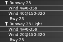
These flows are from an airport which has six flows defined for two usable and parallel runways, 05/23 and 05R/23L . The first two flows are shown here:
The first flow, “Runway 23”, declares that when the wind is at 4kts or lower from any direction or less than 40 knots from somewhere between 150 and 320 degrees, runway 23 and only runway 23 should be used. The runway is restricted to only Jets and Turboprops, which means that the airport is inaccessible for props, helicopters, heavies and fighters.
Firstly, the flow is probably incorrect, because there is also a runway 23L which will never be used at all. In fact, two additional flows exist – one for 23 and one for 23L – neither of which will ever be used because they have identical wind restrictions to “Runway 23” and come after it in the list. This particular airport is popular with GA, so disallowing props is also incorrect – but a likely explanation follows.
The next flow, “Runway 23 Light”, will never be used because there is no circumstance where it satisfies restrictions that are not also satisfied by “Runway 23”; the only difference is the wind restriction, and it is more restrictive (20kts vs 40kts). “Runway 23 Light” allows the runway to only be used by props and helicopters so even if this flow were to be used, which is impossible, it would prevent jets and turboprops from landing if the wind speed was less than 20 knots. Remember that only one flow is ever in use at any time so if no runway in the currently active flow can service your aircraft, you’re out of luck!
In general, if you have considered naming your flows after runways and you have more than one runway, the flows are probably wrong.
What would be more appropriate would be to define four flows for this airport:
W Light, covering runways 23 (a long tarmac runway) and 23L (a shorter grass runway), with “Wind 4@0-359” and “Wind 20@150-320”, with jets and turboprops assigned to runway 23 and props and helicopters assigned to 23L. Heavies should probably remain excluded; fighters are a trickier question because even a WW1 biplane could be defined as a fighter.
W Normal, covering runway 23 only, with “Wind 40@150-320”, again with jets and turboprops assigned to runway 23. This would close the airport to helicopter and small GA aircraft when the wind was above 20 knots, but leave it open for more powerful aircraft.
E Light, a copy of “W Light” but using runways 05 and 05R and with a single wind restriction for “Wind 20@320-150”. It would be pointless to include “Wind 4@0-359” because it has already been satisfied by “W Light”.
E Normal, a copy of “W Normal” using only runway 05 and the wind direction reversed to cover “Wind 20@320-150”.
Debugging Flows and Flow Changes
When the weather changes, X-Plane will wait at least one minute before beginning to change flows. When it starts to change flows, the sim goes through three phases:
Departure drain. All new departures are held, but existing departures are allowed to depart using the old flow. All arrivals continue to arrive using the old flow.
Arrival drain. Once the number of non-held departures falls to zero, all arrivals not on final are re-routed to the new flow. Existing arrivals are allowed to land on the old flow.
Complete change-over. Once the existing legacy arrivals have landed, the new flow is fully in effect and the ground hold is lifted.
Note that if the weather changes back to the old flow in phase 1, the old flow is resumed; if the weather changes back in phase 2, we continue to the new flow.
The logic behind step 1 is: we have to let all taxiing departures depart on the old runway because there might not be enough room for aircraft to turn around on the pavement. While this is happening we don’t re-route arrivals to avoid a head-on collision. The logic behind step 2 is: as long as pending arrivals are arriving in the old runway, we can’t release the gate hold because the departing aircraft might block the arrivals’ route to the gate.
By default the ATC system logs some information about flow changes to Log_ATC.txt, but you can turn on advanced and detailed logging by setting the art control atc/debug/rwy_flow to 1. Detailed logging starts after the art control is set. Log_ATC.txt can be viewed in real-time using the “developer console” menu item in the Special menu.
You can also view more details about runway selection by setting the art control atc/debug/rwy_selection to 1.
Starting with X-Plane 10.50 and WED 1.5, ramp starts can be customized with a lot of data to help specify their use. Ramps starts should be designed based on their use in the real world and should never have aircraft scenery objects placed on them as this would interfere with the “Draw Parked Aircraft” and “AI Aircraft” functions in X-plane 10.50 and newer.
Ramp start definitions are also used when deciding what parking locations are suitable for the user aircraft.
Ramp start type
The majority of ramp starts should be either Gate or Tie-down spots. Static aircraft will show up only at these ramp types.
Misc and hangar type ramp starts should only be used for human player starts. X-Plane will ignore Misc type and will not spawn static aircraft there. When Hangar is set, X-Plane assumes the aircraft is in a building (and therefore not visible) and won’t spend resources placing aircraft there. AI aircraft will use Hangar locations as a last resort if no tie down or gate spots are open, but will not use Misc.
Set only one type from the drop down here.
Equipment Type
This field determines what type of aircraft should use this parking spot. Set at least one type from the drop down here, but multiple types are supported on the same spot. The differentiation between “Heavy Jets” and “Jets” is based on their unladen mass and follows the ICAO standard. As a very rough guide, all aircraft size E or larger are usually classified as “Heavy” and those of size D and below as “Jets” although there are a few size D heavy aircraft. It is recommended to always include both “Heavy Jets” and “Jets” as equipment types for all ramp starts of size D and larger to avoid creating unintended restrictions.
Size
This field determines what size (wingspan) aircraft can be assigned to that spot, both for static and AI/user aircraft. For static aircraft, X-Plane will place aircraft that are marked in X-Plane’s scenery library as the specified size & one lower (i.e., size C will be used by size C & B aircraft).
The classification of these sizes follows ICAO Aircraft Size Standards and is as follows:
Letter
Wingspan
Example
A
<15m
C-172, Baron 58
B
15-24m
King Air C90
C
24-36m
B737, A320, MD80
D
36-52m
B767, A310, MD10
E
52-65m
B777, B747, A340
F
65-80m
A380
Ramp Operation Type
To further limit what type of aircraft can be shown as parked aircraft at that ramp, set an operation type. When set to “none,” no parked aircraft will be placed, but AI aircraft of a suitable size can still use this ramp start. Pick only one type from the drop down here.
Airlines
Case insensitive in WED, three letter ICAO codes as per the Airline Codes Wiki Page separated by spaces. This field also affects both static and user/AI aircraft.
For static aircraft, if you have included more than one airline code in this spot, X-Plane will randomly pick one before the available liveries in the library are checked. If the airline code X-Plane selected is not found in the user’s library, a random result will be placed instead. So limit your definitions to airlines code most people actually have static aircraft installed for, otherwise most people will only see completely random liveries at those starts. X-Plane by default includes liveries for only a small number of major airlines, but these will always work. See the category lib/airport/aircraft/airliners/ for available liveries on ramp starts marked as Operation Type=’Airline’. Or the equivalent categories corresponding to the other operation types, if selected.
For moving aircraft, parking spots which are marked as suitable for the aircraft’s airline will be selected first when assigning parking.
Designing sceneries with Ramp Starts
All ramp starts of types “Tiedown” or “Gate” must be placed to allow aircraft taxing along ATC taxi routes to safely pass any aircraft parked there. To check for interference, switch to the “Taxi+Flow” view mode in WED and verify the yellow aircraft shapes are completely clear of the ATC taxi routes depicted in any color, with preferably 10-20 feet of clearance to spare.
User and AI Parking Allocation
When the ATC system needs to allocate a parking spot for the user or an AI aircraft, both when they are created and when they are about to land, it tries to narrow the choice to the best-matching set before choosing one from that reduced set semi-randomly. The information described above is all used in producing the initial reduced set.
All non-Misc parking spots are searched. Any that are blocked by an aircraft are first excluded, where the user’s aircraft, AI aircraft and static aircraft are all considered. A spot may be blocked by an aircraft parked nearby even if it is not itself allocated.
If nothing is available the search is repeated, dropping restrictions in a defined order, until at least one spot is seen as usable. This order is:
Airline
Operation Type
Equipment Type
Size Class (i.e. allow an aircraft which is too large for this parking spot)
Start Type (i.e. allow the inclusion of Hangar, but not Misc)
If the system is trying to allocate a spot for an aircraft which needs parking and more than one spot is usable at the end of each search, those which match the aircraft’s size class most closely are retained
When any criteria have been ignored, only those spots which form the least-bad match from the resulting set are included. In other words, if some spots match three criteria and some match four, only those which match four criteria will be considered.
Debugging Ramp Starts
If AI don’t seem to be using your airport or ramp starts, there are a couple art controls that you can turn on to help debug the situation. (Note you will need to set the art control then make sure the airport reloads by leaving entirely and coming back.):
atc/debug/log_spawn=1 (Prints log info on AI aircraft arrival & departure logic. Use developer console to see this in-sim)
airp/debug_ramp_starts=1 (Leaves on screen a bunch of visual debug markers telling you about the ramp starts, so if a static airplane is missing or wrong you can SEE the data.)
From X-Plane 12.1.3 on, you can check compatibility with particular aircraft using the new “Usable” toggle in the flight configuration page. Select the aircraft you wish to test and then enter the advanced location selection. If you zoom in a little the airport will show only those spots which are usable for this aircraft type. Bear in mind that this page will also show ‘misc’ starts, which will allow the user to start there but nobody, including the user, to be assigned parking there.
When testing, remember to check multiple aircraft types. Common problems include:
GA parking spots which are not suitable for jets. Use the Cirrus Vision SF50, a class A small jet, to check this.
Large spots (classes D, E and F) which are not marked as usable for Heavy aircraft.
Airports where every spot has the same airline restriction. This happens with some in the US where people have marked every parking location as being usable only by SWA, for example. This effectively means that all SWA aircraft can park anywhere, and that for all other aircraft the airline restriction will have to be ignored, meaning that they can also park anywhere.
A UDP output from X-Plane to drive you own weather radar display… perhaps for your own moving map!
Send the following data to X-Plane’s IP address by UDP into port 49,000:
The 5 chars “RADR” (four chars plus a NULL at the end!) followed by a STRING (also null-terminated of course!) that lists the number of radar points per frame that you want X-Plane to send right back to you
to drive your visual system. So send “RADR_10_”, where the _ is a null, to have X-Plane send you 10 radar data points per frame.
NOTE: X-Plane will send the message right back to the IP address and port number you sent the RADR command FROM!
This is in the settings menu, internet settings screen, right-most tab for data output.
And here is the data that will come to you, with no annoying struct-alignment issues: The data is all perfectly tightly packed with no spacing.
the four chars RADR, and a fifth byte that is internal-use.
float lon longitude of the scan point, which X-Plane will walk around the area
float lat latitude of the scan point, which X-Plane will walk around the area
float bases_meters the cloud basees in meters MSL
float tops_meters the cloud tops in meters MSL
float clouds_ratio clouds present at this lat and lon, as seen from top looking down, ratio
float precip_ratio precip present at this lat and lon, as seen from top looking down, ratio
This article describes how to optimize the performance of scenery and airplanes that use OBJs. OBJs are often the most expensive part of an airplane or scenery pack, so careful construction of OBJs can help.
Identifying Performance Limitations
There are three typical scenarios for object performance tuning:
You have a small number of objects with a lot of detail in each one. Typically you will be constrained on “detail” – that is, the total VRAM used by all objects, total number of vertices, and sometimes attributes. A typical scenario might be an airplane, where there are only 20 objects, but each one uses a huge texture, a huge normal map, and has a ton of vertices.
You have a moderate number of objects, each with a moderate amount of geometry. But do to the repetition, the total vertex count is very high. This is a case where the “leverage” of repeating an object causes problems. A typical case might be a jetway that has a lot of detail and is placed into an airport scenery package 200 times.
You have a huge number of objects; pure object count is the limiting factor, even though the objects themselves are quite trivial. This can happen when objects are used to build cities, e.g. you have 10,000 building objects in a small area.
Before you can optimize your airplane or scenery, you must identify which scenario you are in. The best way to do this is to reduce the ‘cost’ of your scenery/airplane and watch performance change.
Reduce the size of textures in photoshop.
Temporarily remove parts of a model to reduce vertex count.
Remove some objects from the scenery pack.
When you find a crude technique that improves framerate, you know where your costs are.
Optimizing Detail
If you have a few objects and are still having performance problems, there are a few things to look out for:
First, be aware of overall vertex count. X-Plane can handle fairly large models, but at some point you will run out of vertex budget. Use LOD to simplify meshes when viewed from far away. Two notes on LOD use for vertex count:
Don’t use LOD to save a small number of vertices. For example, LOD to reduce from 100 to 50 vertices is not a win for detail-bound models. But if your airplane is 500,000 vertices when viewed up close, LOD might be a real win.
You get maximum performance when an object is not drawn at all because the maximum LOD distance is set low. Separate details that can be eliminated entirely into their own objects, then set their LOD very low to avoid them. The very act of drawing an OBJ is expensive, even if it contains one OBJ, so you save setup costs in this case.
The total amount of texture used by a model or scenery can start to crowd out VRAM. Here LOD is important too. If an object is not drawn at all because we are farther away than its highest LOD, then its texture won’t have to sit in VRAM. But this only works if the texture is not used by any objects.
Organize your textures so that all details are in one texture, then use LOD to try to eliminate details when viewed far away.
Example: if you are building an airport, put all of your trucks, cones, and other small objects into one texture. Keep the terminals separate. The terminals will be visible from 10 miles away, but if all of the details have low LOD, the detail texture may not be used at all when on final approach, cutting down VRAM use.
Be aware that the cockpit object’s texture is never compressed or reduced in size, so use this texture sparingly; use it only for details that must be crisp to make the plane flyable. If the user is running at a low texture setting, there is a reason for it!
Optimizing Leveraged Geometry
When you have a moderate number of high-cost objects, the total geometry can start to add up. For example, 200 jetways with 10,000 vertices each will add two million vertices to the scene. It’s likely that all of the jetways are visible when the user flies over the airport; two million vertices is a lot, particularly when the rest of the world must be drawn too.
When working on an object that will be placed many times and has a lot of detail, use LOD carefully to avoid high vertex count. For example, it’s fine to have a high detail jetway with 10,000 vertices as long as we have another LOD with only 1000 vertices and a reasonable transition distance. At any one time, most jetways won’t be nearby and will take only 1000 vertices (for 200,000 vertices total) with maybe one jetway using 10,000 vertices. That’s almost a 10x savings in vertex count.
But be aware: there is a cost to having lots of LODs, so generally you should only use two or three LODs.
Optimizing Total Object Count
When placing a large number of objects, the object count becomes the most important factor. Most users will have machines that can draw between 3000 and 8000 objects, per frame, depending on rendering settings, hardware, and drivers. When building cities, it’s pretty easy to exceed these numbers.
The most effective way to cut object count is to make the farthest LOD of your objects be not too far away. When an object is beyond its maximum LOD distance, it is not drawn at all, reducing object count. X-Plane is very very fast at eliminating objects that are beyond their LOD distance. For example, X-Plane can easily draw an OBJ for every taxiway light (over 10,000 objects at KORD) because the LOD distance is only 500m on each light . Thus of those 10,000 objects, almost all of them are eliminated rapidly.
When object count gets large, small mistakes in the OBJs themselves start to add up. A single attribute in an OBJ can add one batch and make the OBJ twice as slow on the CPU to draw. For an airplane cockpit this is no problem, but if the OBJ is repeated 5000 times then we’ve added 5000 batches. When building an object that will be placed many times:
Do not use attributes if you can possibly avoid it.
Keep LOD low when possible.
If possible, use only triangles; avoid lines and animation.
OBJ File Format Performance
This section contains some notes regarding the creation of fast OBJ files. This is only of interest if you are working on an export script that creates the OBJ file itself – that is, it deals with how to best organize an OBJ file for maximum speed.
Ordering
Let’s start with the ‘cost’ of everything. Basically, the rough list is (most expensive changes come first: these are the things you do NOT want to interleave):
Changing primitive type (tris vs lines vs lights vs smoke – always put lights last!).
Changing to and from the cockpit texture (try to avoid doing this more than once!!)
Changing “shader” (this includes: poly OS, ATTR_light_level — Material changes)
Animation
“Cheap” attributes (ATTR_hard/ATTR_hard_deck, ATTR_draw_disable). Basically these control which ‘physical’ mesh a tri is part of are the cheapest attributes and lowest priority to optimize.
In other words, you never want to do anything to make your OBJ bigger to optimize out ATTR_hard, because the sim is good at ATTR_hard, but it is very slow at changing to the cockpit texture, so avoid doing that more than once. Within these buckets, there really isn’t much difference – that is, poly_os and blend mode both change shaders, so they have nearly the same cost.
You can avoid ‘small’ batches of two sided by duplicating the geometry and reversing the normal – if an entire OBJ is two sided, ATTR_two_sided _might_ be best, but if a model has only a few two-sided geometry, duplicate the mesh; it can be worth it to create up to 100+ extra triangles to avoid a shader change attribute.
The cost of anim transforms is of course partly in the animation, but part is in the stoppage of drawing. So given a HUGE pile of animation commands, it’s good to have them all in one group. That’s why the XPlane2Blender exporter performs well even though it duplicates the animations (to avoid attribute state) – the result is typically a set of animations, and they’re cheaper in groups.
One other note: if you put the word DEBUG on its own line at the end of your OBJ, X-Plane will output the internal command structure, which is what X-Plane will actually run. It will be different from what you output – some commands are optimized out, and some OBJ commands become multiple X-Plane commands. Generally, shorter output in that log is better, and fewer shader changes are really important. Note that the list contains aesthetic ideas too – e.g. poly_os is before non-poly_os because otherwise the poly_os geometry will look bad!
In the end, the fast path is an OBJ with _no_ internal shader changes; this case is fast no matter what the sort order (since there are no shader changes to sort) but if a user includes shader changes, there is going to be a speed hit.
Almost all lighting billboards come from OBJs, via named lights or custom lights.
They are usually subject to level of detail (LOD). However, there are some exceptions.
Philosophy:
Authors know better than X-Plane when an OBJ should disappear – it’s a subjective thing. X-Plane always honors ATTR_LOD for triangles.
X-Plane knows better than authors when a light should disappear – since X-Plane knows how those abstract light params are rendered. X-Plane may ignore LOD. Usually this involves light being drawn for a longer distance, in cases where there is no perf hit in the rendering enigne. This is almost always desirable for authors.
Guidelines:
Replicate your lights through all LODs with the SAME exact values.
You can drop a light in far LOD but don’t add one.
Notes on implementation:
X-Plane may draw your light for longer than you want – calc will be based on light’s actual appearance.
X-Plane won’t double-draw extended-LOD lights when repeated in two LODs. Not a problem!
Don’t add lights in far LOD – X-Plane may not be able to accurately do this effect if it is tampering with LOD!
If your last LOD is light only, X-Plane can handle this VERY efficiently. So often there is penalty for huge final LOD for a named light that is geo only.
X-Plane 940 allows you to customize the look of the prop disc using a series of datarefs. The idea is to allow a plugin installed in an airplane to provide the rules for prop disc rendering, while letting X-Plane deal with the details of z-buffer thrash and other prop-disc-related artifacts.
Authors who want detailed 3-d props (when not spinning) should continue to build these with a 3-d modeler and turn off the “draw plane part”.
You can download a sample airplane with a custom prop disc driven by a plugin here: File:Example prop disc.zip.
Concepts
A prop is either a disc or not. In disc mode the physical prop is not drawn – instead one or two proxy textures are drawn to simulate the effect of the prop spinning rapidly.
When the prop is not a disc, X-Plane will draw an airfoil for each blade, unless the plane part is disabled for drawing in Plane-Maker.
The prop disc is made up of two parts: the front disc and the side billboard. (The side billboard is not used unless a plugin activates it.) The front disc is a quad normal to the longitudinal axis; the side billboard is a quad normal to the lateral axis. Both spin around the longitudinal axis.
The prop disc texture is used by dividing it into equally sized cells horizontally and vertically and then selecting a cell. Up to two horizontally adjacent cells can be blended; vertical cells cannot. (Vertical cells are intended to provide multiple textures for a main and tail rotor, for example.)
The cell grid does not have to be the same for the prop front and side billboard. For example, a typical layout might divide the texture into 4 cells for prop front discs (using the first 3) and then 16 cells for the prop side billboards, using the last 4.
Each engine has a prop override – when this is 0, X-Plane fills in all other values, managing cell selection, angles and the choice of whether the prop is a disc to match prior behavior. When a plugin sets this override (per engine) all datarefs (including prop angle, which is what makes the prop spin) are under plugin control.
All datarefs are per-engine arrays, for individual control of each engine.
Datarefs
sim/flightmodel2/engines/prop_disc/override
Set this to control the rest of these datarefs.
sim/flightmodel2/engines/prop_is_disc
This dataref can be set to 1 to use billboards and discs or 0 for a physical prop. You can read this dataref even if you are not overriding the prop.
These are the rotation angles of the front disc and side billboard – set by X-Plane unless you override.
Important: you should limit the prop angles to the range of 0-360 degrees while you compute them. While the sim will function with the values out of range, the result of letting the values get very huge is a loss of numeric precision that will cause artifacts during long flights.
Datarefs For Cell Selection
These datarefs control “cell selection” for teh textures:
The s_tim and _t_dim define the number of horizontal axis (s) and vertical axis (t) cells for the prop disc and the side billboard. Make sure they are not zero! The _s and _t datarefs pick which cell; the lower left cell is numbered 0,0.
For the disc_s and side_s datarefs you can pass in fractional numbers to create a blend between two cells…for example, the value 2.25 is a blend of 75% cell number 2 and 25% cell number 3.
Translucency Control
You can control the translucency of each prop disc. For the front disc:
X-Plane will interpolate between the front translucency and side translucency based on the view angle of the camera. So for example if disc_alpha_front is 1.0 and disc_alpha_side is 0.0, the disc will fade out as the camera rotates from front to side.
disc_alpha_inside is a scaler. For example if it was 0.75 then the disc would be 75% as opaque inside the cockpit as it is outside.
These datarefs provide the same service for the side billboard.
If you set this dataref to 1, the side billboard will be aligned to the camera (billboarded) automatically by X-Plane. If you set it to 0 it will be rotated around the longitudinal axis of the engine based on the side_angle dataref.
Revision History:
         01/26/18   Updated with Joining Taxiways to Runways
         06/25/08   Updated With Taxiline Guidelines
         10/25/07   Initial Draft
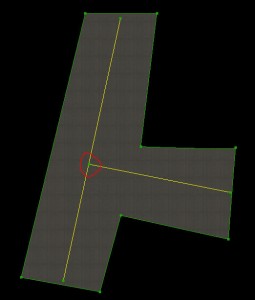
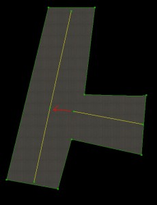
Correct Formation of T Junctions
A “T” junction is any connection between lines in an airport layout where one line ends in the middle of another line. T junctions would include a T-shaped meeting of taxiway lines (shown in these examples), but the junctions formed by the edges of taxiway pavement are also T junctions and need to be formed using the same technique.
The key points are:
Two lines in a WED layout (of any type) should always meet at their endpoints.
One line should not end in the middle of another line.
This means that you must split a line at the point another line intersects it.
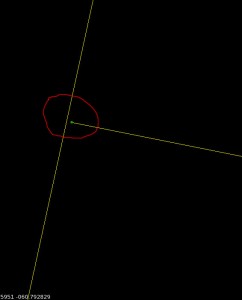
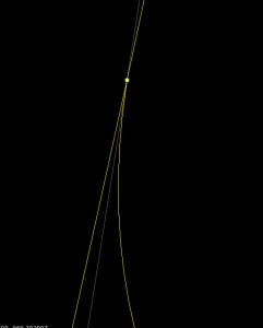
You should not simply attempt to visually line up your layout. Consider this T junction:
It looks correct but upon zooming it becomes clear that the taxiway line ends “near” the next line but is not actually on it. With no vertex to join to, this join can never be clean.
Junctions like this can suffer from all sorts of problems in X-Plane:
The alignment error may look significantly worse in the sim–the only way to guarantee a good connection is to have two vertices with the exact same location.
If one of the lines is a bezier curve, the approximation of the bezier in X-Plane may be different from WED, causing a disconnect.
If these lines were taxiway edges, the “sliver” of a gap could cause bumps when a plane rolls over it or ugly rendering errors in the pavement.
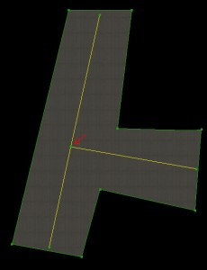
The correct way to build a T junction is a two-step process.
Split one of the lines so there is a vertex at the location where the two nodes will meet. :
Then drag the connecting line to that vertex. In WED you can use the “snap to vertex” option to get precise positioning of the two vertices on top of each other. :
This T junction will look correct at any zoom, and will render correctly in X-Plane.
Remember: close visual alignment in WED is not good enough! You must create an extra vertex and snap the vertices together to create precisely aligned layouts.
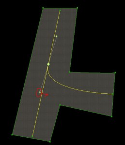
Correct Bezier T Junctions
When a T junction is made up of a bezier curve, another issue comes into play: besides needing the end vertices to be snapped together, the bezier curve handles must not be “over-curved”. Consider this layout:
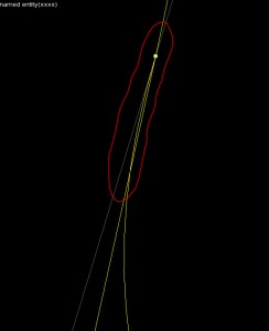
It looks okay in WED, but note that the lower control handle of the bezier curve is on the left side of the straight taxiway line (and yet the bezier curve itself is on the right side. This is a mistake in the layout! Here’s what it looks like close up:
The problem is that the bezier curve control handle (by being on the left side of the taxiway line) pulls the bezier to left a little bit too much. The result is that the bezier crosses over the centerline before joining with it. This error looks small in WED, but in X-Plane, where the taxiway lines aren’t as smooth, the error is significantly more noticeable.
In order to fix this problem, the lower bezier control handle must be on the same side of the joining line as the curve itself–in this case on the right side.
This creates a bezier curve that looks good no matter how closely it is zoomed.
The key here is to err on the side of caution: position the bezier control point on the right side of the connecting line; do not trust the preview of the curve to show if there is a problem.
Do Not Add Extra Vertices to Make Smooth Curves
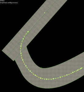
You must add vertices to make T junctions correct. However, you should use the smallest number of vertices possible to correctly describe your layout. For example: this is a bad taxiway line.
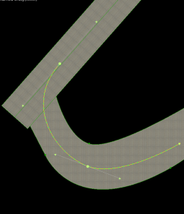
The taxiway line is bad because it uses a huge number of vertices – way more than necessary. The line should be built like this:
Use a small number of bezier curves to shape your lines. Do not add extra vertices in an attempt to make the line look smoother in X-Plane.
X-Plane uses an “error” heuristic to draw taxiway lines–basically it will add vertices to minimize the “squareness” of lines. The problem with adding vertices is that you have to add a very large number of vertices to force X-Plane to render at a higher quality. If you add a few vertices, you increase file size, download time, load time, and RAM use, and X-Plane simply adds fewer of its own points (since fewer are needed to reach the same amount of roundness). Only by adding an insane number of vertices can you markedly improve visual quality; this comes at the expense of RAM use for your layout.
Leave smoothness of lines up to X-Plane; this setting will be wired to the user interface. Some users will need lower rendering quality to use your airport on slower computers. If you add too many vertices, you simply assure that these users cannot fly to your airport at all.
Joining Taxiways to Runways
Taxiways should be drawn to the runway edge, not just to the runway shoulder edge:
Connecting the taxiway to the runway in this manner will result in correctly recessed runway edge lights and a better looking connection between the pavements. The taxiways are automatically drawn above the shoulders and below the runways. If you stop the taxiway at the shoulder edge, it often leaves a gap between the runway pavement and the taxiway.
Comments Off on Correctly Forming Taxiways and Junctions
Draw order within an X-Plane object is deterministic – X-Plane always draws objects in the order of their command structure. Therefore you can control draw order using your 3-d modeling tool.
The ac3d exporter will export models in the order shown in the hierarchy view.
The Blender exporter will sort your model, but will keep groups separated, and will put mesh triangles marked “alpha” last.
LR’s modified blender exporter for v10 (to be staged with v10 – contact LR if you want to merge the changes into another distro) sorts triangles back to front and front to back to help make translucent surfaces work.
X-Plane 10 Only: the order of additive LODs is not guaranteed; X-Plane may draw the LODs in any order.
Layer Groups and Draw Order Between OBJs
All art assets in X-Plane belong to a layer group. Layer groups are always drawn in order, but within a layer group the draw order is unpredictable. This means:
You can force one object to always be drawn before another by putting it in a lower layer group (using ATTR_layer_group).
You cannot dynamically change the draw order at runtime – you must pick which object is drawn first.
You cannot change the draw order based on camera angle.
Note that using layer groups disables X-Plane’s ability to optimize object draw order for performance (because it forces a particular, possibly non-optimal draw order); use layer groups only where you must use them for correct visual output.
These lighting techniques apply to both 2-d panels and 3-d cockpits that use 2-d panels as textures.
Instrument Overlay Lighting Modes
Generic instruments overlays have one of three lighting modes – the lighting mode controls how LIT layers are used and how the instrument reacts to brightness changes. In considering the mode, each instrument has:
A power source.
A rheostat controlling instrument brightness.
Some amount of light falling on the instrument, the sum of ambient, flood, and spot lights.
Built-in instruments typically have either the glass or mechanical mode, but a few are composed of parts that have both properties.
Mechanical Lighting
Mechanical lighting is the simplest mode: the overlays brightness comes from the sum of ambient, flood and spot lighting hitting the instrument overlay. This mode of lighting is appropriate for instrument overlays that simulate mechanical parts, parts that require something to cast light to be seen.
If electric power fails, the instrument is still drawn; the power failure is noticeable because the spot and floods will go dark, reducing the amount of light that falls on the overlay.
For backward compatibility, mechanical lighting will use the _LIT texture when it is dark and the electrical system is on. However, we recommend that you use back-lit lighting for mechanical lit instruments in X-Plane versions 920 and newer. (See below.)
You can cause mechanical lit instruments to disappear using generic instrument filters; this might be appropriate for a mechanical flag, for example.
Glass Lighting
With glass lighting, the instrument brightness rheostat determines the brightness of the instrument. The light cast on the instrument has no effect. This is appropriate for EFIS elements and other “glass” displays. If power fails, the instrument is not drawn at all.
For backward compatibility, mechanical lighting will use the _LIT texture when it is dark and the electrical system is on. However, we recommend that you use not use this feature with glass lighting in X-Plane versions after 920. (See below.)
Back-Lit/Additive Lighting
Back-Lit lighting is a new lighting mode: the daytime texture is drawn based on the sum of ambient, spot and flood lighting; the LIT layer is then added on top of the day time texture (when power is available) at a brightness based on the instrument rheostat.
The result is an instrument that is self-lighting, but still visible due to ambient light if power fails.
Lighting Modes for Non-Generic Instruments
You can set the lighting rheostat property on any instrument, even an old one.
The parts of that instrument that respond to the “instrument brightness” rheostat will now follow any of the 16 lighting values.
This lets you use the moving map and pre-made EFIS elements with multiple lighting rheostats.
In X-Plane 930 and newer, you can set the legacy lighting mode to “mechanical” or “additive” (which corresponds to mechanical or back-lit for generics). Legacy instruments are “glass” or not based on their type, and in fact some parts may be glass while others are not.
Lighting for 2-D Panels Only
Theoretical Model
Under the new 2-d panel lighting model, there are four sources of light:
Ambient light comes from outside the plane – its level is a rough approximation of sun and moon effects (but in the 2-d panel it is not directional.)
The flood light fills the entire panel with a single color, similar to what was available in 902. The flood level is controlled by the panel brightness rheostat (flood light rheostat).
Up to 3 spot lights fill some areas of the panel with a specific color. The spot lights are defined by an RGB color in PlaneMaker and a mask (indicating where they have influence) in a PNG file. Three new rheostats control the spot light brightness individually.
Instrument overlays can also have “emissive” lighting – that is, they can light themselves up regardless of these other effects. Instrument brightness can come from one of sixteen rheostats; default instruments use rheostats 0 and 1 (for pilot and copilot). Old datarefs and instruments keep rheostats 0 and 1 in sync for compatibility with 902 and beyond.
Panel Background Spot Light and Shadow Masks
Four things are necessary to use the new panel spot-light feature:
Include at least one spot light overlay. These overlays have the same name as the panel, with the extensions -2.png, -3.png and -4.png. Their format is a gray-scale PNG (no alpha) of the same size as the main panel. These correspond to each of the three spot-lights.
Change the -1 shadow layer from RGB+alpha to gray-scale, no alpha. In its converted form, white means more shadow, black means no shadow.
Set the RGB colors for the three spot lights in the PlaneMaker view screen (lights sub-tab).
Optional: include rheostats to control the spot light levels.
The change in shadow format is very important: without the spot light system, the shadow uses transparency to overlay a color image. With the shadow format, the shadow is a simple gray-scale mask, with higher values meaning more shadow.
Spot lights affect burned-in instruments on a per-pixel basis; that is, the the spot light masks combine with the background image to produce a lighting effect.
Spot lights affect overlays on a per-instrument basis; that is, the overlays will take on a lighting level from the average of the spot light around the instrument, but one side of an overlay can’t have a different spot-light affect from the other side. The precise way spot lighting is used depends on the lighting mode (see below).
Lighting Tips
Creating Glow Effects With Default Instruments
In X-Plane 930 and newer you can use “additive” lighting with the default instruments – set the lighting mode to “additive” in Plane-Maker and add _LIT-1, _LIT-2 textures etc. to the overlays.
This effect is typically used to make LEDs and back-lit numbers have a warm “glow” at night.
There are two problems with this technique. First, additive lighting can only be used on the overlays of an instrument, e.g. the -1, -2, -3 and -4 layers. So there is no way to make the background glow. For example, if an instrument has its numbers and markings in the background, those can’t be made to glow.
The work-around is to make a new instrument, typically a generic rotary with 1 image cell and no click mode, with additive lighting mode and the image of the glow. The glow goes in the -1 layer.
This glow instrument must be lower in the panel “stack” than the instrument you want to glow. The glow will appear on top of the background (since all backgrounds are drawn before any overlays) but under the moving parts of the regular instrument (which is higher in the sack).
For an example of this, see the default C172 in X-Plane 930 or newer. Since the steam gauges have their markings in the background, the author uses a single large generic to add all the glow effects to the six-pack instruments.
The second problem is that default instruments automatically categorize their layers into lit vs. mechanical lighting…the “additive” option only affects those “mechanical” layers. For example, in the radio stack, the LEDs are automatically categorized as “lit”, so additive lighting is not available for them.
Usually this is not a problem – if the layer is lit, you wouldn’t need glow because the lit texture would already contain this.
Per-Pixel vs. Per-Vertex Limitations
The 2-d “lighting” masks (-2, -3, and -4 layers on the panel background) add light to the panel and instrument background and any burned in elements on a per-pixel basis.
However, due to performance limitations, these effects only affect overlays on a per-vertex basis. That is, the entire overlay is lit uniformly by the -2,-3, or -4 mask based on one sampling point. (The same is true for the -1 shadow layer.)
There is no one good work-around for this…typically you will have to use a combination of careful shaping of the background lighting effects and possible use of lighting overlays to reduce artifacts.
A color profile describes what the meaning of various RGB color triples mean, that is, how red is red?
It is important that the color profile you author your textures with is the same as the one X-Plane uses to show them.
The recommended color profile is sRGB, a standard color profile. You work in sRGB color space, save your files with this marked on the PNG file, and then X-Plane can adjust the color if the user’s display doesn’t match sRGB.
Steps For Correct Color
To maintain correct color, you must do three things:
Author with correct color
Save your work in a way that will not confuse X-Plane
Set up X-Plane to correctly recreate that work
Setting up the Authoring Environment
In order to create a texture that looks right, you need to author in an environment where ‘red’ is really ‘red’. To do this, you need to:
Set your monitor to an sRGB color profile.
Set your painting program to both work and save using the sRGB color space.
Making Sure Textures Are Saved Properly
Your saved PNG files must contain either a gamma chunk that indicates a gamma of 0.45445 or an sRGB chunk or both. How you do this will depend on your painting tools, but one of these chunks must be present for X-Plane to “know” that your texture is authored in sRGB.
If you are working with DDS, use XGrinder and DDSTool – X-Plane’s handling of color correction with DDS textures is [quirky]; using XGrinder/DDSTool ensures that the DDS file is encoded with the same rules X-Plane will use to decode it.
Setting Up Correct Viewing in X-Plane
Finally, to see how the texture looks in sim, keep your monitor calibrated to sRGB and set X-Plane’s gamma setting to 2.2. This will tell X-Plane that it does not need to modify your textures, which are already in sRGB, just like your monitor.
Mac Users: if you are using a version of OS X before 10.6, your monitor’s gamma will probably be set to 1.8. In this case, you can set X-Plane’s gamma to 1.8, but setting the color profile’s gamma to 2.2 might be a more accurate way to work.