Custom lights are always rendered as a textured billboard (no matter what the user’s settings and hardware). The texture of the billboard is a subsection of the OBJ texture. The lighting parameters specify RGBA tinting of the texture, as well as the texture coordinates, and apparent size of the billboard.
Custom lights may have a DataRef associated with them; if the light does have a dataref, that dataref modifies the lighting parameters when the light is drawn, for animated effects.
Like named lights, custom lights are affected by animation (both rotation/translation and show-hide) as well as the object’s position. When a dataref indicates that a light is “directional” in a certain direction, remember that this is relative to the object, and can be affected by animation.
Example: if you attach a landing light to an airplane and put it inside an animation for the landing gear, then the light’s directionality will change as the plane flies and as the gear retracts.
Custom Light Architecture
In order to understand how custom lights work, you must understand that datarefs can act as processing functions as well as sources of information. Behind every dataref is some code (in a plugin or X-Plane) that provides the dataref value.
When a custom light is drawn, the following steps occur:
First, X-Plane starts with the 9 parameters from the OBJ file.
X-Plane passes those 9 parameters to the dataref code (in a plugin or X-Plane) for the custom light (if it has a dataref associated with it).
That custom dataref code can then modify or replace the parameters.
X-Plane then draws the billboard with the parameters (as modified by the plugin).
This process happens each time the light is drawn – that is, the next time the light is drawn, X-Plane starts over with the original OBJ parameters.
Usage Models for Custom Lights and Datarefs
There are a number of ways to use custom lights (with or without datarefs):
Simple Custom Lights
The simplest way to use a custom light is to not use a dataref at all. Your light will be drawn based on the parameters in the OBJ file.
Example: an object uses a custom light with no dataref to make a simple, omnidirectional, always-on light.
Custom Lights with Plugin-Replaced Parameters
A more complex use involves using a plugin that replaces certain parameters.
Example: The dataref sim/graphics/animation/lights/airplane_strobe_light replaces the red, green, and blue parameters with 1.0, an the alpha parameter with 0.0 if the airplane strobes are not flashing or 1.0 if they are. Thus adding this dataref to a custom light makes it into a white strobe.
In this example, some of the light parameters (size, texture coordinates) work normally. Other parameters (RGBA) are replaced by the plugin, so the values in the OBJ file do not matter. You can put any RGBA into your custom light with sim/graphics/animation/lights/airplane_strobe_light and it will always come out white.
Custom Lights with Plugin-Modified Parameters
The most complex case is the one where lighting parameters are interpreted by a plugin and then replaced. In this case the “meaning” of those lighting parameters depends on the dataref.
Example: the dataref sim/graphics/animation/lights/airplane_landing_light interprets the red, green, and blue parameters as a direction vector for the light. The alpha parameter is interpreted as an index number for the landing light switches. So RGB = 0 0 -1 means that the light points toward the front of the aircraft. (This is a light where X = 0, Y = 0, and Z = -1.) A = 2 would mean the third landing light is used; A = 0 means the first landing light. The dataref replaces the RGB values with 1,1,1 (white) and the alpha value with the brightness based on the current camera angle, or 0.0 if the light is off. The result is a directional landing light.
In this example, the meaning of RGBA is completely changed – instead these four parameters form a vector and light number. In return for this flexibility, the author loses control of the tint of the light (because the dataref always sets the light tint to white).
Most X-Plane provided datarefs for lights reinterpret the RGBA values (and replace them with white and a variable-level alpha); lights can be colored by coloring their texture. Typically the texture coordinates and size are not modified.
Custom Lighting Parameters
Nine numeric parameters define the appearance of a custom light. Those parameters are:
Red, Green, Blue, and Alpha Levels. These four numbers define the tinting of the lighting billboard. (The alpha level fades the light out – at alpha=0.0 the light is not drawn.) These numbers are ratios from 0.0 (minimum) to 1.0 (maximum).
Size. This number describes how big the billboard looks. Note that this number is not in meters – the size of lighting billboards changes non-linearly with distance. Use experimentation to tune the light appropriately.
S1, T1, S2, T2. These four numbers define the rectangular texture coordinates from your OBJ texture for the image to use as a billboard.
X-Plane Datarefs for Custom Lights
X-Plane provides a number of datarefs for custom lights. They are all in the path:
You should also read part of: xpsdk: PluginsAndObjects. This documentation is intended for plugin developers but may be useful.
Understanding the Documentation for Custom Light Datarefs
Custom light datarefs typically change the meanings of the 9 lighting parameters (RGBA, size, texture coordinates). For example, you might see this:
INPUTS:

RGBA form a 4-part direction vector - see PluginsAndObjects.

X-Plane 921 and newer: RGB form a 3-part direction vector; A is interpreted as an index number for multiple landing light switches.

OUTPUTS:

Alpha is set to brightness or 0 if it's off. RGB is set to white.

SPECIAL BEHAVIOR:

This light will turn off if the landing light is off.

DESCRIPTION:

This provides a directional light that follows the airplane's landing lights.
The most important sections are “inputs” which tells which of the 9 parameters have special meaning to this dataref, and “outputs” which tells which of the 9 parameters are replaced with new values.
You can find links to the complete list of datarefs here. For datarefs for custom lights, view the HTML datarefs, and click on the link for documentation.
Typical Conventions for Light Datarefs Created by X-Plane
Datarefs provided by X-Plane for custom lights typically have a few common properties:
Custom configuration is always done with the RGBA color parameters.
The color is almost always replaced with white. (The intention is to color your light using the texture.)
Alpha is almost always replaced with the light brightness.
Size and texture are usually left alone.
Mathematics of Directional Lighting Parameters
There are a number of common conventions used by X-Plane for directional lights.
RGBA directional lights
Many light datarefs treat either RGB or RGBA as a “direction vector” for a directional light. For example, the airplane landing and taxi lights do this.
The red, green, and blue lights represent the direction of the light in the X, Y, and Z axis in object coordinates.
For example (assuming the object or plane has a rotation of 0 degrees, e.g. it is facing north):
RGB = 1,0,0 is a light that shines to the east.
RGB = 0,0,-1 is a light that shines to the north.
RGB = 0,1,0 is a light that shines straight up.
RGB = -0.7,0,0.7 is a light that shines to the south-west.
The alpha parameter is a fixed amount of brightness that is always added to the light. So for example, RGBA = (0.5, 0, 0, 0.5) would create a light that shines to the east, but is also always on a little bit. (See “Tricks for directional lights” below.)
RGB directional lights
Some lights only provide RGB for direction. In this case, RGB operates the same as above, but no constant brightness is added. Typically in this case the alpha parameter is used for something else.
RG Rescaling
Some lights indicate “red green rescaling”. In this case, the light always faces north (as if its direction vector was 0,0,-1). However, the magnitude of that direction vector is multiplied by the red value of the light, and the green value is then added. So for example, R=0.5, G=0.5 would create a light that shines to the north with 100% intensity, but in other directions at 50% intensity.
Tricks For Directional Lights
The magnitude of the normal vector can be calculated as:
M = sqrt(x*x+y*y+z*z)
This magnitude affects the overall brightness of the light. Normally you would want M=1 for a light that reaches maximum brightness when the user looks at it. But you can create some interesting effects by using a norma vector such that M is not 1.0.
In particular if M is larger than 1.0 and the constant term of the light (the alpha channel) is negative, the result is a light that is more tightly focused (e.g. it becomes invisible when viewed only a few degrees off axis). Example:
R = 0 G = 0 B = -10 A = -9
In this example, the magnitude of the normal vector M = 10, and the constant term is -9. (Note that B being negative points the light north … B = 10 would point it south. The magnitude is always positive!)
Similarly, if the light is red-green rescaled, you can achieve the same effect with:
R = 10, G = -9
If M is smaller than 1.0, the constant term can be used to widen the light. For example:
R = 0.5, G = 0, B = 0, A = 0.5
In this case, the light won’t fully disappear until directly behind it. For a red-green light, you would use:
R = 0.5, G = 0.5
Plugins and Custom Lights
Plugins can provide custom lights – plugin authors should read xpsdk:PluginsAndObjects for more info. Datarefs provided by plugins for custom lights will not start with sim/graphics… but rather have a plugin-specific prefix. If the plugin is not loaded, the light will show the lighting parameters unmodified.
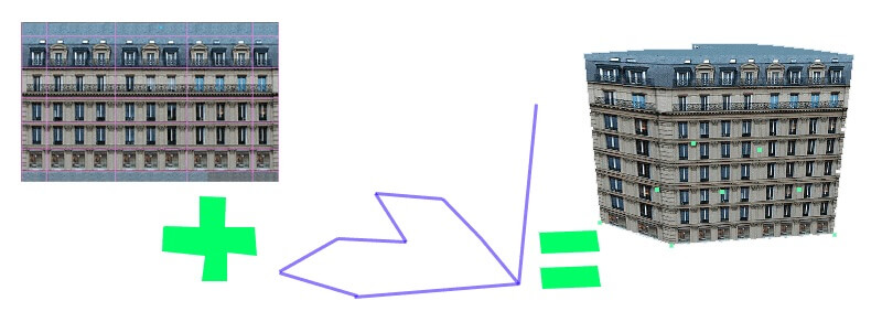
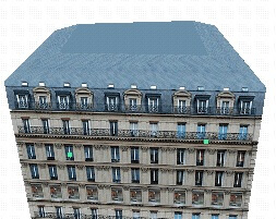
A facade is a special type of object in the X-Plane scenery system. Normally an object is specified as an OBJ file and placed in the scenery at a point and given a heading. With a facade, a facade specification text file (.fac) specifies what texture should be used for the object and how to build flat walls from part of the texture. The facade object is then placed in the scenery file along a polygonal path, and a building is extruded.
Facades allow you to specify a large number of buildings, each with a different shape, using one texture. The facade object is built from your facade specification text file in a smart manner, with the texture being replicated as well as stretched to look good at different sizes.
Facade concepts
A facade specification text file (spelled out in depth here) specifies how to build a facade object along a polygonal path. The facade text file specifies a texture; each facade object may (like OBJ files) use only one texture.
The DSF file will specify a polygonal path for the facade object and the number of floors to build; this lets each facade object be a different height.
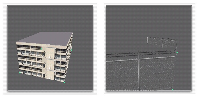
A facade specification text file may designate a ring or chain facade. A ring facade object is a closed loop, which is useful for a building. A chain facade object is simply a set of connected links, which might be useful for a fence, etc.
A facade specification contains one or more levels of detail (LOD), or definitions for what the facade should look like at different distances. Each facade LOD specifies a minimum and maximum viewing distance. The various levels of detail must be continuous without gaps; the facade will not be drawn beyond the last level of detail. (This is the same as for OBJ files.)
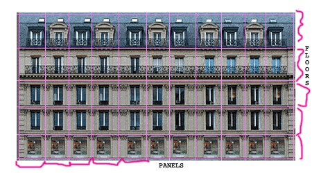
Each LOD for a facade specification is in turn made up of one or more walls. Each wall is broken into a number of horizontal divisions called panels, and vertical divisions called floors. Each wall specifies its panels and floors in terms of the texture for the facade object, as well as a resolution for the texture, to convert from pixels to meters. As a wall in the facade object is stretched or shrunk, panels and floors are added and removed to make the wall the right size. Each floor and panel in a wall can be specified as repeatable or non-repeatable, for visual control of the wall.
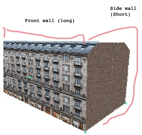
Each wall has a minimum and maximum length; as a facade object is built, x-Plane will look through every wall definition and randomly pick one wall whose length range matches the wall being built inside the sim. This allows you to specify one wall for short building sides and one wall for long building sides.
The roof of a facade (if specified) is always a solid color and is specified as a coordinate on the facade’s texture. Multiple roof coordinates can be provided, in which case X-Plane will pick one randomly.
The top floor of a facade can be sloped inward on a per-wall basis. Strange results may occur if the walls collide when angled.
How X-Plane Selects Facade Panels and Floors
The algorithm for selecting panels and floors is the same horizontally and vertically, and goes like this:
All end tiles are used before any middle tiles.
End tiles are equally balanced on both ends; for an odd number of tiles, the left/bottom end is preferred.
Only middle tiles can be repeated.
Middle tiles are used in left-to-right or bottom-to-top order.
Middle tiles will be split to match their left-right edges where possible.
Example: this horizontal stripe represents 9 panels: ABC = left panels, 123 = middle panels, XYZ = right panels. So the facade texture is organized as:
ABC123XYZ
This is the set of geometry created as the number of panels is increased; spaces represent X-Plane inserting an additional quad to form the shape.
A
A Z
AB Z
AB YZ
ABC YZ
ABC XYZ
ABC1 XYZ
ABC1 3XYZ
ABC123XYZ     <= exact match, only one quad
ABC12 23XYZ
ABC123 23XYZ
ABC123 123XYZ
ABC123 1 123XYZ
ABC123 12 123XYZ
ABC123 123 123XYZ
ABC123 123 1 123XYZ
Facade performance is typically limited by the amount of free memory, not framerate. That is, on most machines, a complex project with a large number of facades will exhaust memory before frame-rate becomes a problem. Most of these tips therefore focus on memory optimizations. (The smallest RAM footprint does also turn into lower vertex count, which is good for frame rate too.)
Correct Winding Order
Facades must be wound counter-clockwise, per the DSF specification. If your facade building’s roof is only visible when TWO_SIDED is set to 1, your facade is wound backward!
No Duplicate Vertices
Do not duplicate any vertices in the facade.
Do not repeat the first vertex as the last vertex; a square facade should have IS_RING 1 and contain only four vertices in the DSF. X-Plane will “close” your loop for you.
Avoid points in a facade that do not define the shape. For example:
1----2----3
|         |
5---------4
Point 2 should be eliminated for performance.
Sloped Roofs
Sloped roofs have some extra requirements:
No duplicate points, and no “straight” points (see above).
The roof is built out of a floor, so most times you will want at least two floors.
The roof should not fold in on itself.
If the facade is wound wrong, sloped roofs will not work.
Reducing Mesh Complexity
The facade engine can consolidate adjacent panels, but it must use more geometry to repeat panels. For this reason, it is best to make a facade wall that contains enough texture and panels to model the largest wall in your facade without repeating/duplicating texture space. A facade can be built in as few as 1-4 quads when geometry is cut, but if the panels are small, repeating the panels burns through a lot of memory.
The facade engine is most efficient when you do not use sloped roofs, the facade is convex in footprint, and the wall definitions match the real size of the facade both vertically and horizontally.
TWO_SIDED
Do not use TWO_SIDED for buildings; use one sided geometry and fix your winding order if necessary. TWO_SIDED is intended only for fences.
In the beginning the taxiway sign specification was a joint effort between FlightGear and X-Plane. The products have since drifted apart; this specification may no longer be applicable to FlightGear. FlightGear users will want to consult their own source.
What is a Taxi Sign?
A taxi sign string is a string of instructions and glyphs that describe an airport sign, usually seen near the sign of a runway or taxiway. See appendix C for examples. We may refer to these throughout the document.
Taxi signs are case sensitive! Throughout the document is phrases like “A-Z”. This means the capital letters A through Z. “a-z” would refer to lower case letters.
Syntax of a Taxi Sign
This is the solid grammar of the spec. It explains what is allowed and not allowed for any reason and would not be logical. -rewrite
The basic rules of a taxi sign are:
No spaces, new lines, tabs (aka whitespace)
Only ASCII printable characters which are supported (see the appendix for quick table of non supported characters)
No incomplete or invalid curly brace pairs
Curly brace pairs
Curly braces, { and }, make up the structure and “clauses” of the string. The 3 rules for curly braces are:
Every curly brace must have one and only one partner
Every curly brace pair must not be empty
No curly brace pair may be in a nesting situation
These rules are not affected or changed by surrounding or containing glyphs, instructions, or semantics.
With this in mind let’s see some examples and why they will fail. (Content of taxi signs here chosen at random and is meaningless)
Example
Why it fails
Correction
{@Y,Q
No right brace
{@Y,Q}
@Y,Q}
No left brace
{@Y,Q}
{@Y,Q}{}{@R,K}
Every curly brace having a buddy, but the middle pair has nothing inside it
{@Y,Q}{@R,K}
{@Y,Q}{@R,K{@L,1}}
{@L,1} is inside of {@R,K}, causing nesting
{@Y,Q}{@R,K}{@L,1}
Glyphs:
A glyph is a symbol representing something, you’re looking at them right now. Letters, icons, symbols are all glyphs, hence why we say “glyphs” instead of “letters”. In the taxi sign string system we have two groups of glyphs, single glyphs and multi glyphs. They each have limitations on where and how they can be expressed. They are also not necessarily in a one to one relationship. To make a space one uses a “_” instead of a ” “. Despite taking up 1 character worth of space a single roman numeral must declared with two characters: “r1”.
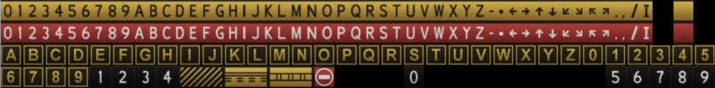
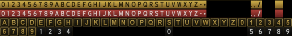
The texture of all glyphs that X-Plane can produce (Found in X-Plane 10\Resources\bitmaps\runways\taxi.dds)
Single glyphs
All the single glyphs in X-Plane
Single glyphs (highlighted above) are glyphs that can generally represent themselves in a single character, for example A, -, 6, etc. Single glyphs can appear inside of a curly brace pair or outside of it. The following are single letter glyphs
A-Z
0-9
– (produces a hyphen)
* (produces a dot)
. (produces a period)
,
/
_ (produces a space)
Multi letter glyphs:
Note that the Roman Letter is repeated to achieve the Roman Numeral 2 and 3
Multi glyphs are glyphs that can only be described using more than one character. Multi letter glyphs include arrows, roman numerals, and special signs such as hazard and no-entry. These must be inside curly braces. Here is the table for it
Multi Letter Glyph Names
Description
^u
Up Arrow
^d
Down Arrow
^l
Left Arrow
^r
Right Arrow
^lu
Left Up Arrow
^ru
Right Up Arrow
^ld
Left Down Arrow
^rd
Right Down Arrow
r1
Roman Numeral I
r2
Roman Numeral II
r3
Roman Numeral III
no-entry
no-entry sign (white circle with horizontal bar on red background)
critical
ILS Critical Area Boundary sign
safety
Runway Safety Area
hazard
Taxiway Ending Marker
comma
The multiglyph version of “,”. Allows to use commas inside curly braces.
Instructions:
Instructions are what tell X-Plane what to do next with the sign. Not all glyphs can be used with all sign instructions. The below table describes the relationship between instruction and glyph.
An instruction must be inside a curly brace and come after a separator. The left curly brace “{” and the comma “,” are these separators.
One can only declare Y, R, L, B, or @ instructions. Once a color instruction has been declared the parser will stick with it. There is no need for something like {@L}123{@L}ABC, however re-declaring a color instruction is harmless.
Instruction Id
Description
Glyphs Supported/Notes
Y
“Direction, Destination, Boundary” (black on yellow)
Supports all valid glyphs
R
“Mandatory Instruction” (white on red with black outline)
Supports all valid glyphs
L
“Location” (yellow text and frame on black)
Supports only A-Z,0-9
B
“Runway Distance Remaining” (white on black)
Supports only 0-9
@
Changing drawing sides
Switches the sign drawing from the front to the back, only allowed once per sign
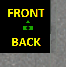
The “@” Instruction aka Frontside/Backside switching:
Signs in X-Plane are single-sided by default, but there is a way to make a sign have content on the front and back of it. The switch side instruction “@” causes X-Plane’s taxi sign builder to start drawing on the opposite side. Look in Appendix C for an example of this.
The @ instruction only switches the side of the sign. The only restriction is that it can only be used once per taxi sign – simply, because a sign only has one front and back!
Here is how the sign “{@Y}FRONT{@@}BACK” would appear in WED with text indicating what side is which appears along which heading:
As stated above, once a color instruction has been declared there is no need to redeclare it. The @ instruction does not change the color. Something like {@Y}123{@@}{@Y}ABC is unnecessary, but harmless.
NOTE: The @ instruction is different from @ used as a declarer; for instance, to use the instruction @, you would need to write “@@”; the first @ declaring that you’re using an instruction and the second @ being the instruction.
Sign Framing
A sign “frame” refers to the separating lines that can appear between parts of a sign. Framing happens automatically when the sign color is changed.
For example, when the sign switches from @L to @R
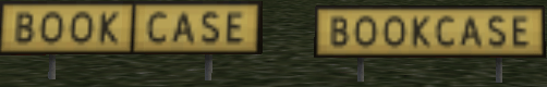
It can also be induced manually using the “|” or “pipe bar” character, found underneath the backspace key on most keyboards. Observe “{@Y}BOOK|CASE” on the left and “{@Y}BOOKCASE”
The pipe bar has some conditions for its usage.
The pipe bar must have the same color glyph next to it on the left and right side. For example {@Y}{^l}|{@R}RIGHT fails because to the left of the pipe bar is a yellow left arrow and to the right is a red R.
The pipe bar can only be used with glyphs that are of colors @Y,@R, and @L. @B is not affected by the pipe bar and as such a sign like “{@B}123” and “{@B}1|2|3” will both appear as the same image on a sign.
Independently colored glyphs (see Appendix D) glyphs cannot be used with the pipe bar.
Pipe bars cannot be adjacent to another pipe bar or a non existent glyph, ex. the start or end of the string. For example the following all fail:
{@Y}123||A – Pipe bars adjacent
|{@Y}123 – Pipe bar at start of the string
{@Y}123| – Pipe bar at end
Separators in a Taxi Sign:
Taxi signs contain, as you know by now, glyphs and instructions. These can be thought of as “elements” of a sign. Each element must be separated from one another. This can be accomplished by using curly braces and commas. The comma, when used inside of a pair of curly braces, becomes a separator. In the sign {@Y,^lu} the comma separates the instruction @Y from the multi glyph ^lu.
Appendix A: Unsupported Characters
These characters are not supported for any reason
!
“
#
$
%
&
‘
(
)
[
]
+
:
;
<
=
>
?
~
b
g
j
k
q
v
w
x
Appendix B: Special rules
^ is a character which is only allowed to be part of a multi glyph, the string {@Y,^} is syntactically valid but it does not make sense because ^ is not a single letter glyph. An error
Appendix C: Table of Examples
Taxi Sign String
X-Plane Rendering
{@L}A
{@Y}{^l}C
{@Y}17-35{^r}
{@B}1
{@R}11-29
{@L}B7{@R}10CAT{r2}/{r3}
{@Y}{^lu}B{@L}C{@Y}C{^u}|F{^r}
{@Y}WEST_APRON{^r}
{@L}P2{@R}16-34CAT{r1}{@Y}{@@}{^lu}P2{@L}P2
Front:Rear:
Appendix D: Independent glyphs
The following glyphs are of the color I. They will always produce one image and are not affected by the current color (in the way that {@Y}{^l} and {@R}{^r} produce a different image
critical
hazard
no-entry
safety
Appendix E: Hidden instructions and error reporting
The following table is a table of instructions that are only used for error reporting and internal usage. They cannot be used by hand.
I
Glyph specific
These are the signs “critical”, no-entry, safety, and hazard, cannot be declared by hand
P
Represents a pipebar, only for error reporting
Indicates the glyph is a pipe bar and should be checked if valid
X
Only for error reporting
Indicates that parsing stopped before any valid color has been found
With the introduction of the new GPS/NAV/COM units we started getting bug reports like this:
New GNS430 COM Frequence not fine adjustable
COM Frequence adjustment sep between xxx.x15 to xxx.x25 is 0.010 and not 0.005 as in other range.
ATIS Frequence at airport CYUL is 120.82 and cannot be tuned in by new GNS430.
or
8.33khz tuning is wrong
The GNS430 actually does 5khz tuning not 8.33khz!
from users and authors wondering why tuning certain frequencies wouldn’t work.
Most of the confusion stems not from 8.33kHz spacing, but from failing to understand the old 25kHz spacing in the first place.
Most COM radios tune in steps of 25kHz, therefore the frequencies available starting from 118.000MHz are 118.025MHz, 118.050MHz, 118.075MHz and so on. Most radios only have five digit-displays so they can only display 5 instead of the actual 6 significant digits of the frequency.
Take for example the ATIS frequency at CYUL, which is given as 120.82. It is important to understand that the decimal value is simply cut off because most mechanical and digital radios only display two decimal digits. The frequency, however is actually 120.825 MHz and not 128.820MHz!
So to tune the frequency that on old radios read 120.82 on one of the new radios you need to tune 120.825 on the three digit display.
Some third-party aircraft allowed tuning settings like 120.81 on their radios. This is WRONG because that is not a valid COM frequency. X-Plane will snap to the nearest available multiple of 25kHz, so if you try to set a frequency of 120.81 via a plugin, using any of the COM radio datarefs, X-Plane will tune 120.800MHz which is the nearest 25kHz frequency.
With a useable COM frequency every 25kHz, the COM frequency range (the “Airband”) from 118.000MHz to 136.975MHz allows for 760 different settings (“channels”), with 100kHz on either side of the emergency frequency of 121.500MHz not assigned for safety. Now, with increasing air traffic density especially in Europe, a different, more fine-grained channel spacing was introduced to allow for even more frequencies: Instead of having a communication channel every 25kHz modern radios have a channel every 8.33kHz, tripling the number of available channels to 2280. With that kind of radio, the available frequencies become 118.000MHz, 118.0083MHz, 118.0166MHz, 118.0250MHz, 118.0333MHz and so on…
As you can see, displaying those frequencies on a radio display would be very inconvenient, because you’d need 7 digits, and reading such a frequency assignment back to an air traffic controller would be a nightmare. Therefore, 8.33kHz spaced communication channels are referred to by a channel number rather than the actual frequency. For the previously existing 25kHz-spaced channels, the channel number is identical to the frequency, so nothing changes here. For the 8.33kHz spaced channels in between that didn’t exist before, the channel is just a number, that doesn’t actually coincide with the frequency! But that does not matter at all, because charts will tell you the channel number and ATC will tell you the channel number, so if you are handed off to “132.010” you simply read back “132.010” and dial in “132.010” on your shiny new radio. In the background, it will actually tune 132.0083MHz, but you don’t care.
X-Plane deals only with channels, as do the controls of any modern radio. In X-Plane, dialling the 132.010 channel means just that – just like your charts or the ATC controller we do not care what the actual frequency is, that’s a detail left to the HF-technicians.
The same holds true for our new datarefs (introduced with X-Plane 10.30) like sim/cockpit2/radios/actuators/com1_frequency_hz_833 the dataref corresponds to what you see on your radio. It is not necessarily a frequency anymore, but a COM channel number. Only for the old 25kHz spaced channels frequency and channel number are identical.
So THAT is the full explanation why tuning one of the new COM radios looks like a “5kHz spacing, but with strange jumps here and there” and why 118.020 is not tuneable, because it is neither a valid frequency nor a valid channel number.
Still not convinced? There is a pretty good explanation by the U.K. Light aircraft association in their magazine “Light Aviation” that really explains everything, complete with a nice little table and some James Bond jokes.
Comments Off on 8.33 kHz radios for users and authors
The Gateway provides a method for airport scenery artists to submit new or updated airport sceneries for inclusion into future releases of X-Plane. Submissions are made (by artists from the community) to the Gateway directly from the Laminar Research airport-building tool “World Editor” (WED). Submissions must comprise only Laminar Research scenery library assets.
Laminar Research thanks all artists for contributing their work to the Airport Scenery Gateway.
Airport submissions are captured by Laminar Research periodically from the Gateway, for inclusion into a future release of X-Plane. Airport submissions that have a status of “Recommended” (by the moderator) at the moment of capture will appear in X-Plane.
The ‘Wanted Airports’ button is a great place to start – this feature provides a list of airports that are missing scenery or have old scenery that needs updating.
If you already have an airport in mind, you may search for it by identifier or name. If this airport is found on the Gateway, select it in the grid.
If the airport does not yet exist on the Gateway, you will need to log in and file a New Airport Code Request
Airport Locking
To avoid two or more artists working on the same airport, the Gateway has a ‘lock’ feature. When an airport is ‘locked’, this informs the community that someone is working on it.
Checking the lock-status of an airport
Log in to the Gateway and search for your airport using the identifier or name. If this airport is found on the Gateway, select it in the grid. The lock-status of the airport is shown above the submission history tree. If the airport is currently ‘locked’, the name of the artist and the lock-expiration date are shown.
Locking an airport
If the airport is available, and you are ready to begin developing it, click the ‘Lock this airport to work on it’ button. Be sure to do this only if you are serious about starting work on the project immediately.
Un-locking an airport
You may release your lock on any airport by clicking the ‘Release Lock’ button. Do this ONLY if you are sure there is no further development work to be done. Once you release an airport, you will not be able to lock it again until a grace-period has elapsed.
Importing an airport from the Gateway into WED
On the Gateway – navigate to the page of the airport you intend to work with and check its submissions-history. If one or more submissions exists for this airport already, you will need to import the Recommended submission into WED as your starting point. If no submissions exist already, you may skip this step.
Start WED and create a new airport project.
Open the new airport project.
Select File | Import From Airport Scenery Gateway
Wait for the list of airports to be populated.
Input the airport identifier or name into the edit box above the list, and then select the airport in the results that are returned.
Click ‘Next’.
Select the ‘Recommended’ submission.
Click ‘Import Packs’.
Exporting an airport from WED to the Gateway
Select the airport you want to upload in the hierarchy pane (you may only upload one airport at a time).
Set the “Target X-Plane Version” in the File menu to “Airport Scenery Gateway.”
Select File | Validate to check your airport for errors. Validation errors will need corrected for the upload feature to become enabled.
Select File | Export to Airport Scenery Gateway.
Input your username, password, and any comments about this work that you wish the moderator and community to see.
Click “Upload.”
Tracking your airport’s progress on the Gateway
Check back periodically to follow the progress of your airport submission on the Gateway. Airports may have the following status:
Uploaded (Not yet acknowledged by the moderator.)
Accepted (This airport submission has been acknowledged by the moderator, but not yet evaluated.)
Approved (This airport submission has been approved as suitable for inclusion in a future release of X-Plane. “Approved” submissions may be downloaded from the Gateway by X-Plane users. However, if there are multiple approved submissions for the same airport, only the “Recommended” submission is a candidate to appear in a future release of X-Plane.)
Recommended (Denoted with a star in the adjacent column – this airport submission has been recommended for inclusion in a future release of X-Plane. Airport submissions that are “Recommended” at the moment of capture will appear in the next release of X-Plane.)
See Comments (This airport submission could not be approved by the moderator. The reason for this can be viewed by clicking the moderator comment that applies to this submission.)
If you encounter any bugs or unexpected issues with WED, the Gateway site, or an airport submission, please report them using the bug reporter on the Gateway site.
Starting with Plane Maker 10.30, authors can select the type of GPS/FMS they would like to use in their plane. The possible selections are:
Old, simplified FMS/GPS which is compatible with older panels and plugins.
This type of FMS uses a list of waypoints, which can be airports, navaids, intersections or lat-lon-defined geographical locations, and uses great-circle courses to go from one waypoint to the next.
Modern, ARINC424 capable FMS.
This type of FMS uses a list of legs, each of which can be one of 23 different path-terminator combinations as defined in the ARINC424 standard, and navigates to each terminator along the defined path.
For each plane, there exist two slots for FMS/GPS, one that works on the pilot side instruments and sources, and one that works on the copilot side instruments and sources. Using HSI selectors, either can be switched to the respective side HSI or CDI, and using the autopilot source selector instrument, each side can be fed into the autopilot.
This settings defines the underlying logic used by X-Plane to manage the flight plan, and create the necessary output for the instruments and autopilot. This is independant of which instruments are installed in the panel, thus the logic can be selected on panel-less aircraft that might be used in professional, multi-machine setups.
Note that the plugin interface that is used by XPLMNavigation only works on the pilot-side FMS/GPS. Also, no advanced functionality of the new FMS is exposed through the plugin interface. From an external view, the “modern” FMS will appear “old” for compatiblity reasons. Exposing some of the advanced functionality to plugins, and making also the copilot side accesible, is subject to a new XPLMNavigation API which will be part of a future XPLM version, whith the particular design yet to be determined.
GPS/FMS panel instruments
Several instruments can be placed in the panel to give the pilot a user-interface to the underlying FMS in the aircraft. The combination of instrument and system define what functionality is available to the pilot. The instrument options are:
GPS_GA, GPS_BC, GPS_HM, FMS and FMS_small.
These instruments have been available since early versions of X-Plane and provide a very easy-to-use interface to the old, simple FMS. If one of this instruments is in the pilot or copilot slot of the panel, the aircraft must use the compatible, simplified FMS in the respective FMS slot (pilot or copilot).
GPS_430_screen and GPS_530_screen.
These instruments are new as of Plane-Maker 10.30. They are screen-only instruments for use by designers who create their own bezels, especially for use in 3d-cockpits. They provide access to popup window-style instruments, and can be used by commands that can be triggered from 3d-cockpit elements. They work on the new, advanced FMS, so to use them, the respective pilot or copilot slot must be equipped with the new, advanced FMS.
GPS_430.
This instrument has been available since X-Plane 9 and consists of a small screen and a bezel with controls around it. It has been used by designers to model various GPS navigators, both panel-mounted and handheld types. By default, it uses the old, simplified FMS/GPS logic and can only be used for direct-to navigation. As of X-Plane 10.30 however, it can also be driven by the new logic and support complex flightplans. So whether this instrument behaves old-style or new-style is determined by which FMS system is installed in the plane in the respective slot. In case the new system is used and the screen is too small to accomodate all UI elements, a simplified UI the old-style default nav page is displayed unless the instrument is installed with a larger scaling providing more screen estate. Because the simplified UI doesn’t play well with some custom-designed aircraft, it is not enabled by default. To make the GPS_430 instrument work on the new logic, the designer must enable the new FMS system for it.
Pilot and Co-Pilot GPS/FMS
Until X-Plane 10.25, the order in which GPS instruments were dropped into the panel in Plane-Maker’s panel editor determined which would work on COM/NAV/GPS1 and COM/NAV/GPS2. This is actually not desireable, since the first one you dropped into the panel would always work on the pilot side, no matter where you placed it. As of X-Plane 10.30, the unit for the copilot must be explicitly flagged to work on COM/NAV/GPS 2. This is done by selecting the “copilot” checkbox in the bottom bar of the panel editor for the instrument. In order to have one panel instrument work on the FMS installed in the copilot slot, you have to check the copilot box on the instrument.
Comments Off on Old vs. new style FMS/GPS in Plane Maker, screen-only units and pilot vs. copilot side
Modern aircraft have severals devices used for navigation, usually VOR/LOC receivers for radio navigation and a GPS navigator or FMS computer for area navigation (RNAV). These devices all provide information on the course to fly, as well as some lateral offset to the planned course.
CDIs and HSIs display that information, and also feed it to the flight director or autopilot, so the pilot can track a course or radial using the desired autoflight system.
Which means of navigation is displayed on the HSI and fed into the autopilot is determined by a source selector, also called the NAV/GPS switch. Depending on the equipment in your plane, X-Plane simulates two types of source selectors found in the real world. The difference is very subtle, so here’s the full explanation:
Analog source switching
Analog source switching is found in most general aviation aircraft that have an older GPS navigator or a GPS retrofitted into the panel. In that case, you have usually two sets of wires going into the source selector, one from a VOR receiver and one from the GPS, and only one set of wires going out to the HSI. The source selector then determines whether the NAV/VOR/LOC or the GPS signal is fed to the HSI. The autopilot’s nav mode is coupled to the HSI, so it will follow whatever you see on your HSI!
In X-Plane, that type of switch can be placed on the panel, variants exist that have either NAV1/NAV2/GPS/FMS or subsets of sources selectable.
The key point to remember here is: Several signals from different devices go into the source selector, and you select one output.
Integrated NAV/GPS switching
Integrated switching is found in more modern equipment with GPS units that are approach-capable and have built-in nav receivers. An example is the very popular GNS430W by Garmin. These devices combine a NAV receiver and a GPS navigator in one piece of panel hardware. In these approach capable navigators there is usually one switch to select whether the device should output VOR or GPS navigation information. On a GNS430W that switch is labelled “CDI” and toggles a selection that can either read “VLOC”, meaning VOR or LOCalizer signal from the nav receiver, or “GPS”, meaning the GPS navigator. Because here the nav receiver is integral part of the avionic, there is no separate wiring and no separate source selector outside the device itself. The device has only one signal output, and that is fed to the HSI, CDI and/or autopilot.
The key point to remember here is: Only one signal comes from the device, and the signal’s source is determined internally.
What’s the difference in X-Plane 10.30+ ?
In X-Plane, both of these switches are controlled by the same type of panel instrument, the HSI source selector, and the same datarefs sim/cockpit2/radios/actuators/HSI_source_select_pilot for the pilot’s side and sim/cockpit2/radios/actuators/HSI_source_select_copilot for the copilot’s side.
The difference becomes obvious when you install a non-switched analogue CDI instrument in your panel:
In case of the analog HSI switch and a non-approach capable GPS or old-school FMS, the CDI is not switched and simply displays the source it has been wired to in Plane-Maker.
In case of the integrated switch, the CDI is wired to the integrated unit and it will display whatever has been selected inside this unit. You may install the CDI source indicator instrument in the panel as a visual reminder to the pilot. More modern CDIs also feature an integral green light for that.
The latter is necessary to comply with FAA-regulations: For a GPS to be approach certified, it needs to drive an external CDI or HSI. That means in panels without an HSI, the CDI has to be capable of indicating the GPS navigation, otherwise the installation cannot be certified for GPS approaches under IFR.
Comments Off on NAV/GPS Source Selectors, CDIs, HSIs and the New GPS Navigator
As of X-plane 10.30+, there are many options to configure the autopilot of a plane, and especially where this autopilot gets its input data from.
Some of these options have been available since much earlier versions, but they are not widely used correctly by designers, so they deserve a more thorough explanation.
Attitude source
This is the most important setting. It allows you to select AHRS, electric gyro or vacuum gyro. It determines under which circumstances the autopilot will stay functional in abnormal situations.
AHRS – choose this option when you are making a modern plane with G1000 or Avidyne glass panels or when making a modern airliner. The autopilot will use the electronic attitude and heading reference system to determine steering commands. AHRS only requires electric power, so it depends on a power source, alternator or battery, to function. AHRS is pretty robust as it works entirely without moving parts, using solid-state accelerometers and rotation rate sensors. The latter are sometimes called gyroscopes, but are really solid-state electronics and have no rotating parts.
vacuum gyro – choose this option when modeling a general aviation aircraft with vacuum gyros equipped with an attitude-based two- or three-axis autopilot. Modern autopilots like the S-TEC Fifty Five are examples of this kind of autopilot. This system uses air pressure (or, lack thereof) to drive mechanical gyros which provide attitude information to the pilot’s attitude indicator instrument and the autopilot. Vacuum systems are usually less reliable and vacuum pumps tend to malfunction at the worst possible times.
electric gyro – choose this option when making a general aviation plane equipped with a rate-based two-axis autopilot like the popular Bendix-King KAP-140. This option is very popular in real-world installations, as the autopilot will still work with a vacuum failure! It will of course stop working in case of a complete electrical failure, that is with a broken generator and a depleted battery. The electric gyro in the turn coordinator is very reliable and provides bank rate and turn rate information to the autopilot, thus giving an indirect indication of bank angle. Because of that it can only provide two, but not three-axis guidance.
Heading source
This determines what provides heading information to the autopilot and the kind of performance to expect from that:
AHARS – electronic AHARS systems determine yaw rate by solid-state gyroscopes and use a fluxgate sensor to detect the earth’s magnetic field. They provide extremely accurate and reliable information on the magnetic heading of the airplane. Choose this option when making a modern glass-cockpit GA aircraft or an airliner.
vacuum gyro – the directional gyro found in most non-glass general aviation planes is driven by the vacuum system, just like the attitude indicator. These directional gyros are not slaved to fluxgate sensors, but must be manually adjusted by the pilot, by comparing their indication to the magnetic compass in unaccelerated straight-and-level flight. This must be done to compensate for gyro precession errors that inevitably occur. With failure of the vacuum pump, this kind of heading indicator will stop working completely. Choose this option for non-glass general aviation planes with vacuum systems.
electric gyro: This kind of gyro works like the vacuum one in that it is not fluxgate-slaved, but rather than using the vacuum system to spin the gyro, it uses an electric motor for that, which is often more reliable. Choose this option when making a general-aviation plane without a vacuum system, like early Cirrus SR-20s and -22s before they were equipped with glass-cockpits.
Nav course source
This is a new option as of X-Plane 10.30, with an additional setting added in X-Plane 11. To intercept and track a nav source, like a VOR radial, a localizer, or a GPS track, the autopilot must know the radial or DTK (desired track). This angle information can come from different sources with different types of autopilots, so you can choose the one that most closely reflects the setup of the airplane you are modelling:
GPS/LOC: the autopilot takes course to intercept in nav/loc mode from either GPS or localizer and from OBS selector when tracking a VOR radial. The autopilot will know what course to track and intercept when flying a localizer or GPS track, even if the HSI is misplaced. This is what is usually found in modern airplanes, with autopilots like G1000 or S-Tec Fivty Five or in airliners. This type of autopilot is capable of tracking and coupling, and can do dual-mode intercepts. This is the default setting that X-Plane 9 always used. When combining this type of autopilot with the new X-Plane 430 GPS navigator, it supports GPSS-mode (GPS steering) with turn anticipation and can also fly DME arcs or fixed-radius RNAV legs.
OBS: the autopilot takes the course to intercept in nav/loc/gps mode from the OBS setting of the selected nav source and the associated HSI or CDI. Here it is very important that the pilot selects the correct front course on the HSI/CDI in order for the autopilot to track localizers or a GPS track correctly. General aviation autopilots like most Centuries and the Bendix/King KAP-140 work like this when the plane is equipped with an HSI. Tracking/coupling and dual-mode intercepts are supported. In combination with the new 430 GPS navigator it has no GPSS support and no automatic turn anticipation. Automatic flying of DME arcs is not possible unless the pilot adjusts the HSI manually.
HDG: the autopilot takes the course to intercept in nav/loc mode from the heading bug, even when tracking a VOR radial. It is important that the pilot always sets the heading bug to the desired front course, otherwise the autopilot cannot intercept and track a radial, localizer, or GPS track correctly. Tracking and coupling works when the correct front course is selected using the heading bug. Dual-mode intercepts are not possible with that type of autopilot, nor is GPSS. Simpler and older general aviation autopilots work like this. The popular Bendix-King KAP-140 works like this when no HSI is installed in the plane.
The HDG with GPSS mode has been replaced by two new types of using GPSS, which are available with the autopilots of X-Plane 11.30. HDG with GPSS: This setting is new as of X-Plane 11. The autopilot takes the course to intercept in VOR nav/LOC app mode from the heading bug when tracking a VOR radial or localizer. It is important that the pilot always sets the heading bug to the desired front course, otherwise the autopilot cannot intercept and track a radial or localizer. Tracking and coupling works when the correct front course is selected using the heading bug. Dual-mode intercepts to VOR radials and localizers are not possible with that type of autopilot. However, when the navigation source is the GPS, the autopilot gets GPS steering (GPSS) information and thus works with turn anticipation and can also fly DME arcs or fixed-radius RNAV legs. The S-Tec Fivty-Five autopilot works like this when installed in an airplane which does not have an HSI.
None: The autopilot gets no information at all on front course or desired track in any mode. This is a very old and basic type of autopilot that can only track a VOR radial once captured, but not intercept it. It only reacts to raw CDI deflection. Classic Sperry autopilots found in vintage planes worked like this. Obviously, only course tracking is possible, but not coupling or any kind of automatic intercept or even GPSS.
Plane-Maker allows you to attach multiple OBJ model files to your airplane. OBJs are 3-d models built with a 3-d modeling program. You can attach several OBJs to your airplane to model different parts of the plane with multiple textures.
Plane-Maker provides a number of properties for each attached object that controls how X-Plane draws the object. This article explains those properties in detail.
Object Lighting Options
Each object can be set to one of three modes:
Exterior: use this option for solid objects that model the airplane’s exterior. These objects are lit by the exterior Plane-Maker lights (e.g. the landing light) and scenery lights (E.g. apron lights).
Internal: use this option for solid objects that model the airplane’s interior. Only these objects receive 3-d internal lighting when HDR is not available.
Glass: these objects are drawn last to avoid transparency artifacts. Put all translucent elements in their own object(s) and set them to glass to avoid Z buffer and transparency artifacts.
When HDR spill lights are used, the HDR spill lights from exterior objects light other exterior objects (and scenery), while the HDR spill lights on the interior objects only light other interior objects.
Glass objects are not subject to HDR spill lighting and should not have HDR spill lights attached themselves.
Resolution Boost (X-Plane 10.02 and later)
This option boosts the texture resolution of an object to the maximum possible resolution. Use this option with caution; it override the user’s texture resolution settings. If a user has turned down their texture resolution, it is almost always to avoid overloading a lower-tier GPU. Use this option only where critical to keep your airplane performant on lower-end GPUs.
For aircraft predating X-Plane 10.02, resolution boost is defaulted to off.
Shadow Mode (X-Plane 10.04 and later)
Shadow mode lets you control the conditions under which an object casts shadows. Removing airplane-attached objects (particularly complex ones) from shadow equations can improve framerate with shadows enabled, so you can optimize your airplane’s fps by carefully limiting shadow casting to only the objects that matter. The choices are:
None. The object does not cast a shadow at all. This is a good choice for translucent objects (where the shadows will look wrong) and any objects that are always in shadow themselves.
Interior only. The object casts shadows in the 3-d cockpit but not out into the world. This is a good choice for small objects inside the plane, e.g. seats.
Exterior only. The object casts shadows into the 3-d world but not into the cockpit. This option is dangerous, as most planes need to cast shadows onto themselves – use with caution!
All Views. The object casts shadows under all conditions.
For aircraft predating X-Plane 10.04, shadow mode is defaulted to “all”, for the most correct (but least optimized) shadows.
This option is not available for “glass” objects because they do not cast shadows.
Pre-Fill Object (X-Plane 10.04 and later)
Normally X-Plane draws the entire outside world before drawing the 3-d cockpit. This ensures that translucency is handled correctly, and allows X-Plane to draw without depth buffer artifacts.
Unfortunately, this process can be very wasteful. If an airliner is flying into clouds, perhaps half of the screen will be filled with clouds only then to be overdrawn with the panel. The GPU work spent “filling” behind the panel with clouds is wasted.
This option tells X-Plane to mask out the clouds and other scenery drawing using this particular object when in the 3-d cockpit. This will save a lot of fill rate on the GPU, at the cost of drawing the object twice (once before clouds to mask, then again after clouds to form the real cockpit). A few guidelines as to when to use this option:
Only pre-fill objects that are totally opaque. Translucent objects will cause errors when pre-filled.
Do use pre-fill when an object blocks a lot of the view from the cockpit. For example, the interior cockpit shell makes a good pre-fill object.
Do not pre-fill when an object is expensive to draw, e.g. if it has a lot of animations.
Do not pre-fill objects that are typically off screen while flying, as that has no benefit.
Performance Tip: often the front object of an airplane will have cut-outs in the main panel for the glass displays of the cockpit object. This means it doesn’t do as good of a job as it could to mask out clouds. Rather than also pre-fill the cockpit object (which will typically have a ton of manipulators, animations, and other expensive stuff), simply put an extra quad behind the panel in the nose of the plane, to block out any sky leakage. This one quad is cheap to draw but will help pre-fill a lot in views where the glass displays dominate the screen.
For aircraft predating X-Plane 10.04, pre-fill is defaulted to off, saving OBJ drawing time and avoiding artifacts, at the cost of an optimization overlooked.
Use LOD (X-Plane 10.04 and later)
X-Plane 9 ignored the final LOD directive on airplane-attached objects, drawing objects to arbitrary distances. Sometimes this is desirable (particularly for wings and other large features) but it also means that an AI airplane drawn far away still draws all of its attached objects, no matter how small.
Enabling “use LOD” causes the LOD directive of the airplane attached objects to work just like scenery objects: after the final LOD distance, the object is not drawn at all, saving bus bandwidth, CPU time, and vertex count.
Enable this option (and define a particular low LOD) for objects that won’t be missed from far away. For example, the interior seats of an airliner aren’t visible from far away through the airliner windows, and can be removed using LOD.
For aircraft pre-dating X-Plane 10.04, LOD is disabled to match X-Plane 9 behaviors.
Dim LIT (X-Plane 10.10 and later)
X-Plane 10 features “dynamic exposure”: during the day, the brightness of LIT textures is reduced to simulate the effect of the sun outshining artificial light. Dynamic exposure is automatic for scenery, but for aircraft, you must enable the feature using the “Dim LIT” check-box.
Enable this option for any source of light that would be diminished or harder to see during the day time. Dim LIT is usually a good idea for all lights on the airplane exterior and also for baked light in an airplane cabin.
Disable this feature for lights that must be fully visible even during the day. For example, if your landing gear indicators are implemented via a lit texture, do not check Dim LIT; if you did enable Dim LIT then they would be hard to see during the day.
Kill Dataref
You can specify a dataref that, when it has a non-zero value, disables an attached object from being drawn. This feature is provided to let authors of complex custom aircraft optimize performance. See this article for details.
Special Handling for the Cockpit Object
The “cockpit object” (the object named by the ACF plus _cockpit) normally acts like an “interior” object; a check-box will give it glass behavior. However, we recommend that you use separate objects for glass. The cockpit object is always resolution-boosted; therefore its texture should be minimized.
In X-Plane 10.10 the cockpit object features all options of the other attached objects except for resolution boost (which is always enabled.)
Note that in X-Plane 10.10 you can use the panel texture from any attached object. Therefore you can make the cockpit object non-glass and an attached texture glass and use the panel texture from both.
Comments Off on Attached Object Properties in Plane-Maker