This is a beta so make backups of your work before using!
New features!
Custom Spill Lights
Custom Spill Lights are now implemented (#312)! To use, make a light datablock with the XPlane2Blender light type as Custom Spill. Relevant properties are:
Property
Function
Light Color
RGB color for the light
Light Rotation
Spot light direction
Light Spot Size
The width of spot light
Size
Size parameter (in meters)?
Dataref
Dataref that controls the light
Custom Spill lights can make dataref driven custom omni-directional billboards and directional spot lights. As with Automatic Lights, the goal is What You See Is What You Get.
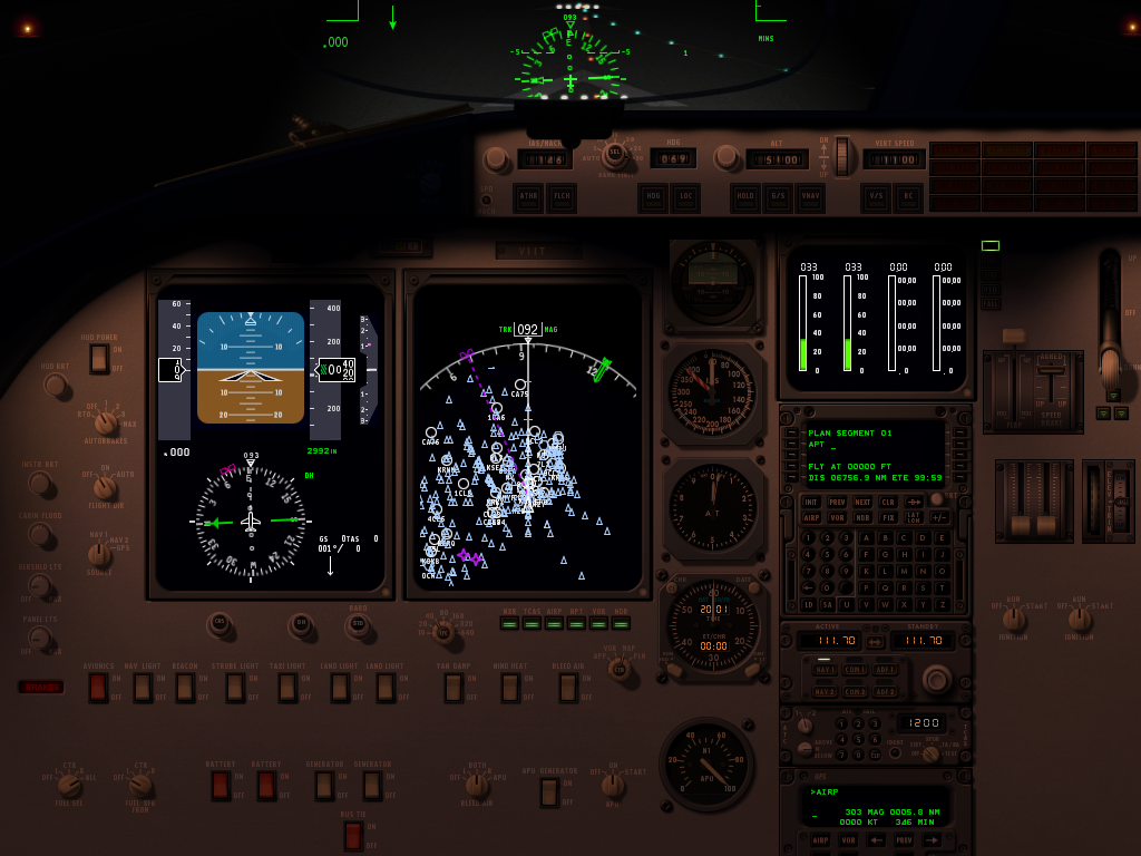
In this photo the green light is a Custom Spill, where sim/graphics/animation/lights/traffic_light changes the color between green, yellow, and red! The white lights have different widths, all made without doing any math by hand.
Cockpit Device
X-Plane has pre-made high quality GPS devices that are easily accessible to the artist. Thanks to (#481) using one is as simple as making a mesh, and giving it a material with a Cockpit Device set. Pick the device, at least 1 electrical bus (matching Plane Maker), the lighting channel, and if the screen’s brightness should auto-adjust. You’ll get a fully functional GPS device just like that! You can have multiple devices in the same OBJ, as well as use of the panel texture.
The Cessna’s cockpit provides 2 great examples of using cockpit devices.
Cockpit Features UI
Given the changes and additions to our Cockpit Features, the UI has been changed slightly. On the material Properties tab use the “Cockpit Features” to find “Cockpit Regions” and “Cockpit Device”. The updater should adjust the setting for you if you were using regions.
Minor features
(#426) Shadow Blend’s Blend Ratio can finally be set. Thanks @kbrandwijk! (#548) Non-Exporting Lights are back in. They’re intended as “work lights” and will never ever show up in the OBJ! Simply set the X-Plane Light Type to “Non-Exporting” and use freely.
Important fixes
Light Level can now be used multiple times in the same .obj without tricks or getting lucky!
Thanks to everyone who downloaded alpha.1! I’m glad that this series has been so successful and I can wait to see what you make with the new light features! As always make backups!
This alpha contains changes to the updater. Make backups before using!
Global Material Settings -> OBJ Settings
This new version contains one of the most requested fixes (#357, #599) for XPlane2Blender: Normal Metalness, Blend Glass, and Global Tint have been moved out of the Material Properties Tab and into OBJ Settings! The annoying “All Materials in an obj must have the same Normal Metalness/Blend Glass Value” error is gone!
The updater tries its best to guess if you wanted Normal Metalness, Blend Glass, or Global Tint, however it isn’t perfect. If you have to manually correct more than 3 of your OBJ settings, please tell me.
These new settings can be found under the Textures section of the OBJ Settings.
Emissive Panel Texture Only and Panel Mode Selector
#595 Also known as ATTR_cockpit_lit_only, this directive has actually been in X-Plane since 11.10, but now is accessible in XPlane2Blender! It makes a panel only use the emissive “Lit” texture – a great speed boost if that is all you need. This is the perfect feature for computer displays.
For Aircraft or Cockpit export types, look in the Cockpit section for “Panel Mode”. This changes the meaning of “Part of Cockpit Panel” for the whole OBJ. Setting it to “Emissive Panel Texture Only” mode activates the feature. You cannot mix panel modes.
Cockpit Regions
People who use Cockpit Regions will have to manually change “Panel Mode” from Default to Regions to see the UI and have regions export again. A one time fix. A future updater will do it for you. Until then I hope it isn’t too many OBJs to change.
Updater Version History Synchronization
#471 The updater now synchronizes its last version across every scene and new updater functions will not use data cleaning to protect against accidental or purposeful updater re-runs. Simply put this means a safer to use XPlane2Blender (but still make backups). Since this is new updater code, however, it had to be put in an alpha. People with multiple scenes should be especially on the look out for problems. I feel very confident about it however.
With testers and users like the ones XPlane2Blender has we’ll be getting to v4.1.0-rc.1 much much much much faster this time! For the users who requested moving Normal Metalness and Blend Glass, thank you for your patience. I know now just how annoying that error message was! I’ll certainly keep this experience in mind for future decisions and don’t worry, “make it the same across every material” is not going to be chosen again without an extremely important reason!
XPlane2Blender is now X-Plane 11.30 ready! Not much has changed since beta.3, just some fixes to the particle stuff.
Bug Fixes
#373 – Test Script’s –filter flags now needs less escaping for its regexes #377 – Show/Hide animations on empties is now being exported again #384 – Particle follow non-colocated animations
Sound Emitter has been removed from the Empty Special types menu. One day it will be back in!
This beta brings in many new bug fixes and heavily requested new features! As with any beta, be aware that this could break your project SO MAKE BACKUPS! We don’t think there are any drastic changes to the data model, but, better safe than sorry.
Bug Fixes
#355 – A small UI fix relating to too many manipulator fields being shown
#360 – A bug fix for Drag Rotate manipulators giving false negatives
#353, #363, and #260 – All relate to warning people and correct what was allowed with NORMAL_METALNESS and BLEND_GLASS. Previously Blend Glass was in the same drop down menu as Alpha Blend, Alpha Cutoff, and Alpha Shadow. Now it is a checkbox allowing you to correctly specify a Blend Mode and apply Blend Glass to it. Existing materials with Blend Glass will see this new checkbox automatically checked. Blend Mode will be set to Alpha Blend or, if your plane is old enough to have been worked on during X-Plane 10, it will be set to whatever it was back then.
See the internal text block “Updater Log” for a list of what got updated, including this. You may see, for example: INFO: Set material "Material_SHADOW_BLEND_GLASS"'s Blend Glass property to true and its Blend Mode to Shadow
#366 – An Optimization! Useless transitions in the OBJ were being written, now they’re not. Custom Properties still work, there won’t be any visual changes to your OBJ. We haven’t done any profiling but it might have decreased OBJ loading time by a small amount too.
Features
Command Search Window
Thanks to #361, just like the Datarefs.txt Search Window, we now have the same capabilities for searching Commands.txt (for manipulators). We are shipping with X-Plane’s latest Commands.txt file, but of course you can replace it with your own (as long as you keep the name the same). One day we hope to make it much more flexible.
Particle Emitters (not very useful to most yet, I know)
Thanks to #358, some people who have access to X-Plane’s cutting edge particle code can use XPlane2Blender to specify particle emitters. Don’t worry, we’re all working as hard as we can to get these into the hands of others. Fortunately, XPlane2Blender users can hit the ground running the minute it drops!
Build Scripts And Test Runners
#302 and #307 – Are you a professional XPlane2Blender maintainer and developer (if so we should probably talk!) Then you need a better build script, and a test script to match! Introducing mkbuild.py, the build script for the modern developer! It creates, it tests, it renames without messy mistake prone human intervention! To top that off, how about a testing script that doesn’t give false positives!
These smaller features are likely to be overshadowed by the release of the G1000 for default aircraft in 11.10, so I decided to dedicate a blog post to promote the articles I’ve written – you can find them among all the guides for aircraft developers: //developer.x-plane.com/docs/aircraft/
Electric and remote gyro systems
Back in April, I flew a Mooney M20J with a KCS55A HSI in it, and realised that it was impossible to model in X-Plane correctly, so I got to work. See the manual for an explanation of this popular HSI/remote gyro system.
I’ve written a usage guide on the new datarefs and commands that I added, along with some more detailed explanation of all the different gyro systems X-Plane simulates, in this guide for aircraft developers. I also talked about the systems at length in a Youtube live stream earlier this year.
Separate GPSS autopilot mode
This is a feature that many add-on aircraft already simulate to some degree, but by means of more or less reliable plugin trickery. The X-Plane 11 default 737 and 747 are no exception. With X-Plane 11.10, a separate GPS steering mode for the autopilot becomes a standard feature.
The new datarefs and commands are explained in detail here.
Screen-only popup instrument windows
Several people who build home-cockpit setups have asked about removing the bezels from the popup displays, so they can have only the screen of a GNS430/530, FMS or G1000 instrument to put on an external monitor, with a hardware bezel around it. While this can already be achieved through some clever hacking in the Miscellaneous.prf file, we now offer a more straightforward way to do this: The popup and pop-out windows now get their bezel graphics from the library system, so you can override the bezel graphics. How to override the bezel with nothing, if your bezel is made of hardware? Simply supply a 1×1 pixel blank .png as a bezel graphic, and X-Plane will know that you really want no bezel at all. In the case of a bezel-less 430, you’d put a 1×1 pixel png as the “cockpit/radios/GPS FMS/Garmin_430_2d.png” resource of your plane.
Please tell me what confuses you about XPlane2Blender on this bug, or here!
We are going to be releasing the XPlane2Blender 3.4 beta soon, and with it, a refresh of the UI and documentation. Thanks to a great e-mail about a lack of documentation, it was put as an important part of 3.4 release roadmap. It goes to show… we can’t fix it if we don’t know what’s wrong, even if its not a code problem. And we do want to fix it, I swear!
In addition, I want to remind everyone a core part of the Laminar Research philosophy, identity, and business plan is a thriving modding and third-party plugin ecosystem. Aside from build scripts and the like, Laminar Research employees use the same scenery development tools that are available to all. This is was a deliberate choice that elevates everyone to the same level – except when there is a gap of knowledge. This is never intentional, and never benefits anyone in the long run, especially third-party-devs. If your work is suffering because we forgot that not everyone knows what every little checkbox means, tell us! We’ll put it in the bug queue like everything else, and try to get back to you, personally, quickly.
Here are three obscure Plane-Maker/X-Plane features that can save you time if you developer complex aircraft.
Plane-Maker Will Copy Your Instruments
You may know that in Plane-Maker, you make your own copies of X-Plane’s PNG files to customize the look of the instruments. But did you know that Plane-Maker will copy the images for you?
Select an instrument and type Control-P (which is the default for the command binding “pln/panel/copy_instrument_png”). Plane-Maker will copy all PNGs for that instrument into your aircraft’s cockpit or cockpit_3d folder. This can save you the time spent wading through X-Plane’s cockpit folder to find the right PNG files.
X-Plane Can Make a Panel Image for UV-Mapping
When you are making a 3-d cockpit, you use the 3-d panel as a texture. But how do you know how to UV-map this texture in your cockpit? Often the panel background (panel.png) is blank.
X-Plane can make a snapshot of your panel for you, in the exact size you need to UV map. Use Control-Alt-Shift-Space (Command-Option-Shift-Space for Mac nerds) to run the “sim/operation/make_panel_previews” command in X-Plane. It will make a PNG file in your aircraft called Panel_preview.png – it’s just like Panel.png but with the instruments drawn in – perfect for UV mapping.
Plane-Maker Will Tell You What’s Wrong
That sad face icon in top bar of the Plane-Maker panel editor enables “warning” mode. In warning mode, every instrument that has a potential problem gets a red outline. Select one instrument with a red outline and in the upper left corner of the panel you’ll see a description of what’s wrong.
This picture on the left is from Plane-Maker editing a 3-d panel. (That’s why it is just a “packed” set of instruments with no background; this panel is used as a texture for a 3-d cockpit – each instrument is UV-mapped into the right location.)
The air-speed indicator has been flagged as having a problem, and the text shows it. In this case, the lit texture has an alpha channel, which causes the lit texture to draw incorrectly. Fix the texture and the warning will go away.
I strongly recommend checking all Plane-Maker “red boxes” on your plane – most of the warnings will tell you about problems that would otherwise be very hard to detect.
This is a feature I looked at putting into X-Plane 9, but it turned out that it affects so many different parts of the sim (and has to be done all-or-nothing) that it got kicked to v10. Consider these two pictures of the default B777 (the lighting was not adjusted, only the time of day):
The night image looks pretty, but what’s wrong with the day image? The answer is: the small panel post lights in the night image are still casting a fair amount of light in the day image. And the result looks silly. But why?
The answer is: in real life your pupils would contract in the sun, letting in less light. The sun is really rather bright, so the daytime panel would still look normal, but the apparent power of those posts lights would be a lot less, because your eyes are less sensitive. In other words, the relative strength of the sun and post lights is wrong in the second image.
Computer monitors don’t have a huge dynamic range for how much brightness they can put out. So we can’t hope to display the absolute brightness of the scene correctly. Instead we need to make everything brighter at night (to simulate your night vision) and dimmer during the day, like this:
In this set of images, the night image is matched precisely to the previous one, but as the sun comes out, the apparent brightness of all lit textures has been scaled down to simulate the effect of your eye becoming less sensitive due to the flood of sunlight.
What’s good about the compensated image is that the weird artifacts from the post lights are gone; the relative strength of the post lights is really low in relative terms.
What happened to the EFIS and moving map? The answer is that they too are not as apparently bright relative to the sun as they would be at night.
There is one hitch here: plenty of real airplanes have light sensors for various avionics; the avionics will automatically turn up their brightness during the day. So it is possible (I am no expert on the 777) that in the real plane, as the sun rises, you might not have to adjust your instrument brightness; the sensor would do it for you. The pictures above illustrate what you would see if no automatic adjustment is made.
Auto-adjustment presents a challenge: currently two wrongs make a right. We don’t auto-adjust the brightness of instruments, but we don’t simulate the apparent visual brightness relative to the sun, and the result are instruments that look adequately bright at all times of day without user adjustment.
I think in the productized version of this feature, authors will have two options for anything lit:
Tie the lit instrument/texture to an auto-adjusting rheostat (e.g. brightness 1 + auto adjustment) or
Tie the lit instrument to the “raw” rheostat (e.g. brightness 1).
The tricky part will be finding the right mapping for legacy airplanes into the new system.
I sometimes get questions from authors considering how much to rely on a 2-d panel mapped to 3-d via the panel texture vs. a true 3-d panel. I can’t comment on what will look best, but I can comment on the relative performance characteristics of both techniques, and the answer might surprise you: in some cases you’ll get better performance by modeling directly in 3-d.
The 2-D Way
When you use the panel texture to make an object, X-Plane goes through a lot of steps to create the final result:
Your panel has to be rendered in 2-d. We atlas your panel textures, but we don’t necessarily order them optimally – we don’t know the optimal order. Each generic instrument is at least one batch, perhaps even two. Those batches have very low vertex count, and the vertices are stored non-optimally on the CPU. There may be a fair number of texture changes between instruments.
If you use ATTR_cockpit_region, we then go back and do the same thing…again! Why? Well, we need your panel’s raw color (“albedo” to graphics nerds) and the emissive light given off by anything self-lit separately, so that we can do correct 3-d lighting.
Both of these are rendered to an off-screen texture that the video driver will feeel obligated to preserve at all costs, putting pressure on VRAM.
Only when all that is done do we begin drawing your object, with the usual batches to change to panel texture and change back, perform animations, etc.
If this seems expensive, that’s because it is. Periodically users send me airplanes to look at their performance, and lately I’ve been seeing a lot more problems with 2-d panels (that fuel 3-d cockpits) being the performance bottleneck, not the 3-d modeling itself.
The 3-d Way
What if we want to go 3-d? Well, we’re going to “eat” a lot more of what your 3-d pit already has:
You’ll need a lot more animations to move all of those parts.
You’ll need new batches with ATTR_lit_level to dial up and down various lighting levels.
But you do get some advantages:
Geometry in objects is processed about as optimally as we possibly can. All of that work we’ve done on the rendering engine to make OBJs fast is available in your cockpit. So you can increase 3-d detail ‘for free’.
Your lit geometry can be drawn in a single pass (we don’t need to prepare two separate lit textures). So for example a needle would take three batches via the panel-texture route (a batch to rotate the needle for albedo, a second batch to draw the rotated night needle, and a third batch to draw the resulting texture in 3-d) but only one if you use the OBJ directly.
Since you organize your textures for OBJs, you can guarantee that all of the cockpit stuff is together, saving texture thrash.
You can use normal maps to add per pixel detail to your cockpit; panel textured geometry cannot be normal mapped.
A Balancing Act
Given the high cost of panel texture relative to native OBJ drawing, you’d think going native OBJ would be a no-brainer, right? Well, not quite.
A needle is an easy case: you can model a needle using a rotation animation, so your implementation in an OBJ and our generic instrument are quite similar. Same with the throttle lever generic instrument.
But what about a “glass pie indicator”? What about a moving map? What about a rotary?
There are some generic instruments that have “movement” for which there is no equivalent OBJ technique. With these generics, the generic instrument/panel code may be able to render the generic quite a bit more directly than your OBJ can simulate the same effect.
This is my suggestion on a cut-off: if you can directly model a generic instrument with an OBJ (needles, throttles, and other “simple moving things”), consider 3-d. If you would have to use a lot of extra texture space, copies of your mesh, or a lot of show-hides, use the panel texture.
Your goal should not be to eliminate the use of panel texture. But if you can cut panel texture down to a single 1024 x 1024 region from a larger area, you’ll probably see a performance win or a reduction in your airplane’s system requirements.
Performance Test First
Final thought: before you invest months in a complex cockpit design, mock up the “work-load” X-Plane must do and performance test it! For an OBJ, simply make one moving instrument and duplicate the mesh to get the number of expected animations. For the panel, drag out a bunch of instruments, make custom textures and just paint junk into them with photoshop. The goal is to make X-Plane do the same amount of work as it will in the final version. Then fly your test panel on target computers and observe performance.
There is no need to use the 3-d panel if you only want 3-d cockpit.
That might be the most counter-intuitive statement in the entire universe. Let’s break it down and see what’s going on. Originally we had the 2-D panel. The 2-D panel was where you put your instruments for interior views. When 3-d cockpit support was added, the 2-D panel was used to create the panel texture – that is, the instruments texture for the 3-D cockpit.
Thiat worked for a while, but as handles became more complex, screens became larger, and as 3-D cockpits became a more complex, authors started to run into the system’s limitations. If the author wanted to create a huge panel, then the panel texture for the 3-D cockpit was huge. Furthermore, texture space for the instruments in the 3-D cockpit was wasted because the 2-D panel had to have windows on it.
With X-Plane and 9 we added the 3-D panel to fix these problems. The 3-D panel is a second panel whose sole purpose is to provide instruments as a texture for the 3-D cockpit. When you have a 2-D panel and a 3-D panel, the 2-D panel is used to draw the panel in 2-D viewing modes and 3-D panel is used only to create the panel texture for the 3-D cockpit. With this setup the 2-D panel can be huge, and the 3-D panel can be small and compact with no windows.
The 3-D panel solves a second problem as well. Often the overhead panel is drawn in perspective on the 2-D panel this perspective view is useless for texturing a true 3-D cockpit. With a 2-D panel and a 3-D panel, the author can draw the overhead in perspective for the 2-D panel, and orthographically for the 3-D panel.
Now here’s where things get complicated: if an airplane has no 3-D panel the 2-D panel is used for both the 2-D view and the 3-D cockpit. But some airplanes have only a 3-D cockpit. In this case, there is no reason to use the 3-D panel at all. You can simply use the 2-D panel for texturing the 3-D cockpit and not worry about the user seeing it; in a 3-D only plane the user will only see the panel as a texture for the 3-D cockpit.
This setup is confusing in name: how can you have a 2-D panel used for a 3-D cockpits? But it is an allowed configuration. In fact, it was the only configuration allowed in X-Plane 8.
In summary: a 3-D cockpit can use the 2-D panel or 3-D panel as its panel texture. If an airplane has no 2-D panel, then the 2-D panel can be used for the 3-D cockpits without problems. In this situation and there is no need for a 3-D panel.
(It might be better to think of the 2-D panel and three panels simply add his two panels so that you can have two different versions of the panel. The names to the panel and 3-D panel are really just labels.)