X-Plane 12 uses an IGRF13-based grid for magnetic variation between July 2021 and June 2024. Within these dates, X-Plane’s magnetic variation will change over time based on real time.
Magnetic variation in X-Plane depends on the UTC date of the operating system’s clock, not the simulated time in X-Plane. That means, you can chose the date and time of your flight in X-Plane to be whatever you like to fly over your favourite seasonal forests, but the magnetic variation will always reflect the current real time.
Note that if your operating system’s clock is set earlier than July 2021 for any reason, the annual change in magnetic variation is capped there. It is generally required that you keep your operating system clock in sync with real time, especially if you want to use up-to-date navdata.
Datarefs of the form:
sim/flightmodel2/wing/dataref_name[N]
give you information about the wings – in particular, they tell you the degrees of deflection of the flaps, elevators, etc. etc.
But what number do you use for N?
The answer is: you pick “N” depending on which airfoil you are animating!
In X-Plane, the horizontal and vertical stabilizers are “wings” too – we call anything that has an airfoil a wing. So you use this table to pick an N that matches what you are doing.
Good:
sim/flightmodel2/wing/aileron1_deg[0] # left aileron
sim/flightmodel2/wing/aileron1_deg[1] # right aileron
sim/flightmodel2/wing/elevator1_deg[8] # left elevator
sim/flightmodel2/wing/elevator1_deg[9] # right elevator
sim/flightmodel2/wing/rudder1_deg[10] # rudder
Usually not good:
sim/flightmodel2/wing/aileron1_deg[8] # aileron on an hstab??
sim/flightmodel2/wing/aileron1_deg[10] # aileron on a rudder?!
sim/flightmodel2/wing/elevator1_deg[0] # elevator on a wing?
sim/flightmodel2/wing/elevator1_deg[10] # elevator on a rudder?
sim/flightmodel2/wing/rudder1_deg[0] # rudder on a wing??
The moral of the story is: pick an array index that matches the part of the plane you are trying to animate!
Unusual Airplanes
The second list is titled “usually not good” above because there are airplanes with rudders on the wings (think of a flying wing) or V-tails where the tail is half-rudder, half-elevator. The rule still applies: use the index that you are animating! So if you have a rudder on your wing, then use index 0 (left wing 1) for the left wing, etc. The important thing is to pick an array index that matches the Plane Maker part.
Why Is It Like This?
X-Plane is a completely flexible simulator: it lets you put any control surface on any flying surface. If you want to make an experimental design with elevators on the wings, X-Plane is not going to stop you.
In particular, because any flying surface can have any control surface, the datarefs are set up with array indices for all flying surfaces for all control surfaces.
But if your airplane does not have rudders on the wings, the value of those daterfs won’t be useful – they might be ‘correct’, they might be zero, they might be wrong. Don’t trust them! Use the correct array index for the correct wing and your plane will work correctly.
Here are three obscure Plane-Maker/X-Plane features that can save you time if you develop complex aircraft.
Plane-Maker Will Copy Your Instruments
You may know that in Plane-Maker, you make your own copies of X-Plane’s PNG files to customize the look of the instruments. But did you know that Plane-Maker will copy the images for you?
Select an instrument and type Control-P (which is the default for the command binding “pln/panel/copy_instrument_png”). Plane-Maker will copy all PNGs for that instrument into your aircraft’s cockpit or cockpit_3d folder. This can save you the time spent wading through X-Plane’s cockpit folder to find the right PNG files.
X-Plane Can Make a Panel Image for UV-Mapping
When you are making a 3-d cockpit, you use the 3-d panel as a texture. But how do you know how to UV-map this texture in your cockpit? Often the panel background (panel.png) is blank.
X-Plane can make a snapshot of your panel for you, in the exact size you need to UV map. Use Control-Alt-Shift-Space (Control-Option-Shift-Space for Mac) to run the “sim/operation/make_panel_previews” command in X-Plane. It will make a PNG file in your aircraft’s Cockpit/-PANELS- folder called Panel_preview.png – it’s just like Panel.png but with the instruments drawn in – perfect for UV mapping.
Plane-Maker Will Tell You What’s Wrong
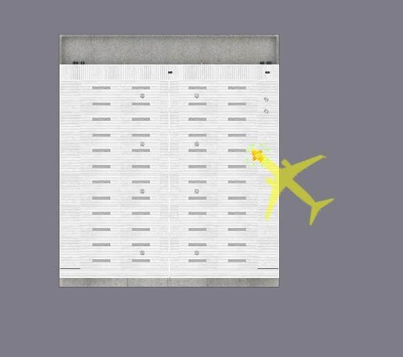
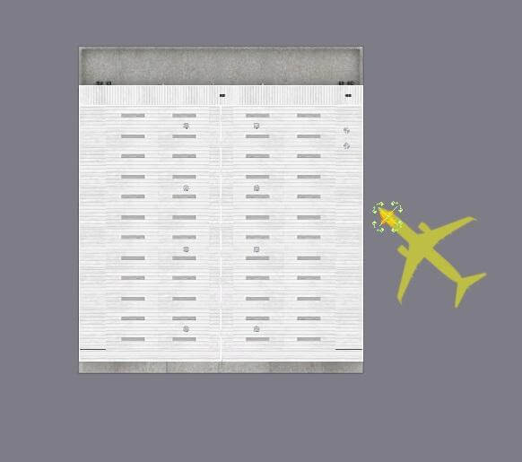
That sad face icon in the top bar of the Plane-Maker panel editor enables “warning” mode. In warning mode, every instrument that has a potential problem gets a red outline. Select one instrument with a red outline and in the upper left corner of the panel you’ll see a description of what’s wrong.
 This picture on the left is from Plane-Maker editing a 3-d panel. (That’s why it is just a “packed” set of instruments with no background; this panel is used as a texture for a 3-d cockpit – each instrument is UV-mapped into the right location.)
The air-speed indicator has been flagged as having a problem, and the text shows it. In this case, the lit texture has an alpha channel, which causes the lit texture to draw incorrectly. Fix the texture and the warning will go away.
I strongly recommend checking all Plane-Maker “red boxes” on your plane – most of the warnings will tell you about problems that would otherwise be very hard to detect.
Preconditions
To get the correct governor type for a fixed-shaft turboprop, you need to set both the engine type and the failure mode of the prop governor correctly. Then, the prop must be configured for sensible blade angles to achieve correct alpha and beta. Correct behavior of the governor requires correct set up of the prop first. The below guide assumes that:
- you have a “fixed turboprop” type on the engines 2 page.
- you have selected the loss of oil pressure position of the governor to “startlock” on the prop engines spec page.
- you have “constant speed” as the type of the propeller on the props 1 page.
- you have ticked the boxes to allow the prop to go into beta as well as reverse on the engine 1 page.
- you have set up the minimum alpha pitch as fine pitch on the prop 1 page. With the prop at this pitch, it should generate a substantial forward thrust at 0 airspeed.
- you have set up the beta pitch on the engine 1 page. At this pitch, the prop should be generating close to 0 thrust at 0 airspeed.
- you have set up the reverse pitch aft of the beta pitch on the engine 1 page so that the prop can generate negative thrust.
Setting up governed speeds
There’s two governing functions that control the speed of the shaft: The prop governor controls it in alpha mode, and the fuel delivery control controls it in beta mode. The prop governor usually only controls the speed within a range of 96% to 100% of nominal RPM, while the fuel delivery control varies the engine speed between around 60% to 96% of nominal RPM. To set up the governing speeds you need to:
- Provide the nominal (100%) speed in RPM as the “redline engine RPM” speed
- Provide the same 100% speed as the “top of the green arc engine RPM” speed (for correct indication, does not effect governor simulation)
- Provide the minimum alpha speed for the prop governor as the “bottom of green arc engine RPM” – this is usually 96% of the nominal RPM. This value will be used as the lowest selectable for the prop governor in alpha mode and also for the underspeed governor that will increase fuel flow to keep the RPM up in alpha mode.
- Provide the lower limit for beta operation (65-73% of nominal RPM on most installations) as “minimum governor speed engine RPM”. This is the minimum RPM achievable in beta with the prop speed lever as far back as to not cross over into feather. This is the lowest RPM that can be set with fuel delivery control.
Setting up the engine idle fuel adjustments
Fuel delivery control works by manipulating the “idle_speed_ratio” actuator, so it changes the idle speed between “low_idle_ratio” and “high_idle_ratio” to govern the engine speed in beta mode. In order to do so effectively, you must tweak the low and high idle to be suitable for the governor. To do so, start up X-Plane and run these two tests:
- Place the power lever just below flight idle, in the tiniest bit of beta you can get. Basically, toggle into beta mode and then advance to beta_ref=0.01 or just the tiniest bit of beta. This way, the prop will be at or very close to the minimum alpha angle, thus grabbing the highest load it can get without crossing over into alpha fully. With the engine speed lever fully forward, the fuel delivery control must now achieve bottom of green arc RPM – usually around 96%. It will do so by running up the “idle speed ratio” towards high idle. Now tweak the “high idle ratio” parameter such that the governor sets an idle speed ratio close to 1.0. In other words, we want the fuel delivery control to be using close to all of its idle fuel here. The engine should be operating very close to the maximum idle ratio. Note the “high_idle_ratio” dataref now.
- Place the power lever as far back into beta without getting reverse thrust. With a properly set up prop, that means beta_ref=1.0. The prop is now at full beta pitch and should be producing very little thrust now and provide the lowest load on the engine. Observe that fuel delivery control will have lowered the idle speed ratio somewhat because it doesn’t need as much fuel flow now to keep the engine turning at min green RPM. Now pull the speed lever back as far as it goes without going into feather. You should be at about 2% travel on the prop axis to achieve minimum RPM short of feather. This will cause the fuel delivery control to call for a very low idle speed ratio to get the RPM down to the minimum governed RPM now, which will typically be between 65-73%. Now, tweak the “low idle ratio” so that the governor will use about 0.3 of “idle speed ratio” to achieve this lowest governed RPM (we need about 30% room below for the engine to spool down). Write down that “low idle ratio” dataref now.
Now back in Plane Maker, on the engines 1 page, set the parameters “hi idle fuel adjustment” and “low idle fuel adjustment” to the two values obtained.
Only with the idle parameters set sensibly, you will get proper response going in and out of beta mode, i.e. when going from flight to ground idle.
Finally, you probably will find that the “throttle available at max reverse lever position” should be low. During reverse, as the prop moves from beta pitch towards reverse pitch, it picks up more load, and this is counteracted by fuel delivery control, keeping engine speed up at the bottom of the green arc. Only if you find that at your reverse pitch you need additional throttle (more than fuel delivery control will provide) to keep the RPM up, should you allow for more throttle here.
General
Preferences Menu
You can access the global preferences from under the File (Windows) or WED (Mac) menu option. Here you can change between meters or feet, and how coordinates are displayed. (Note that Moderator mode is only useful if you are a Gateway Moderator so always leave this turned off.)
Preset METAR ICAO
WED will automatically create meaningful wind/time rules names based on the airport METAR ICAO and time a relevant properties for any Wind, Time or Runway Use rules is changed. This keeps the flow rules more legible, the flow rule name itself has no relevance outside WED.
Updating old data
Smart runway rename
When a runway is renamed due to magnetic variation changes, not only the runway name, but also all ATC taxi routes, flows and taxi signs need to be fixed to match the changed designation. WED will detect such edits of a runway “name” property, find all these references, update them and let you know. This greatly helps when the runway validation tells you it’s missing some runway at that airport – which usually means some existing runway was recently renamed due to magnetic variation changes.
After changes of the runway name property a popup windows will announce the number of changed ATC taxi routes/ Flow rules / 3D Taxi signs to confirm the smart rename action.
To change a runway name without invoking the smart renamer, first change the runway name to some illegal name, then in a second operation to the desired new runway name.
Align Airports
Select an airport, then go to Airport menu > Align Airports. This function can be used to mass-move the currently selected airports to bring runways into CIFP compliance. It will also select only unchanged airports after the operation completed, to facilitate deletion and re-submission of only the changed airports to the gateway.
Explode special AGPs
Edit > Explode Special AGPs takes certain scenery .agp group objects (such as lib/airport/Ramp_Equipment/ 250cm_Jetway_Group.agp) and replaces them with the individual .obj components included in the group. You can further modify that “group” by moving or deleting the individual objects that make up the group.
This only works for a few predetermined public .agp groups, mostly these jetway groups. It also requires that all items in that .agp group are available as individual .obj items for placement in WED.
Replace Vehicle Objects
Edit > Replace Vehicle Objects takes X-Plane 10 sceneries and replaces all .objs depicting ground service vehicles found on all airports in the scenery and replaces each one with the equivalent X-Plane 11 Ground Service Vehicle start definitions. E.g. it turns the static Belt_Loader.obj into the X-Plane 11 service vehicle that actually moves around.
This function can be used in conjunction with the previous one to first break up the jetway groups into the individual .objs (Belt_Loaders, Baggage Trains, GPUs etc) and then convert those pieces into Ground Service Vehicle starts if applicable.
This feature sounds nice at first, but the Ground Service Vehicle starts really need to be placed strategically near a Ground Vehicle Route to really “work” right. But it’s a quick way to create lots of strangely behaving ground vehicle traffic.
Upgrade Ramps
Airport > Upgrade Ramps takes pre-X-Plane 10.50 sceneries with ramp starts and adds useful defaults for the X-Plane 10.50 properties that were added to those starts. Also deletes certain .obj known to depict static aircraft in the vicinity of these ramp starts, so as to eliminate conflicts with the X-Plane “Draw Parked Aircraft” function.
E.g. all ramp starts of type = Gate start get Operation type = Airline added, all type = Tiedown turn into either Airline or General Aviation operations, depending on the ramp start size parameters.
Scenery artists tend to draw wide airport boundaries to “defend” their airport against overlapping objects from all kinds of default and addon sceneries. But in the long term, this does more harm than good. While there is no firm rule on what is “too close” or “too wide” for airport boundaries, airport boundaries can greatly affect scenery results after an X-Plane update or version change.
Scenery is typically only recut between versions, and the airport boundary is what is used to flatten and shape the area around an airport.
Having a tight boundary with tens or hundreds of nodes can greatly affect the detail of the surroudning base mesh. The terrain mesh uses terrain triangles to follow the airport boundary exactly, as it is not allowed to simplify (aka cut corners) here. If there are a lot of nodes in the boundary, the terrain will require a lot of triangles which reduces the detail available for the rest of the 1×1 degree tile area.
The airport boundary is NOT a tool to trace political/legal boundaries or to determine where the airport grass should be visible or not. It is to define the area where your particular layout needs to have (somewhat) flat and level ground and to be free of 3D autogen/addon scenery items. (Note that roads are not 3D items, so these are not affected by airport boundaries.)
This document contains some quick visual tips for avoiding common pitfalls that cause airports to get declined by the Gateway moderator. Situations vary, and these suggestions may not apply in all instances.
In World Editor (WED)
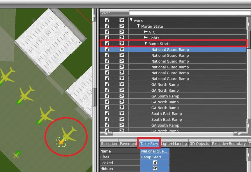
Ramp Starts
Place WED in “Taxi+Flow” Mode when working with ramp starts. Ramp start footprints are displayed which are useful for managing incursions.
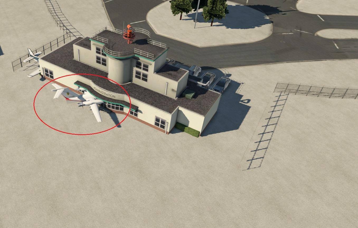
Examples of incursions:
Appropriateness of ramp sizes is also considered:
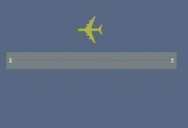
WRONG
(Too large for the runway at this airport.) |
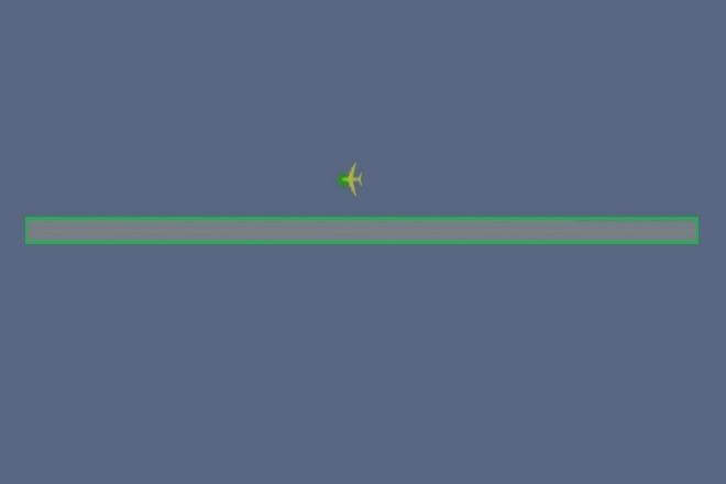
RIGHT
(Suited to the runway at this airport.) |
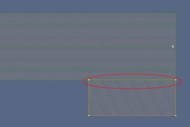
Taxiway / Runways
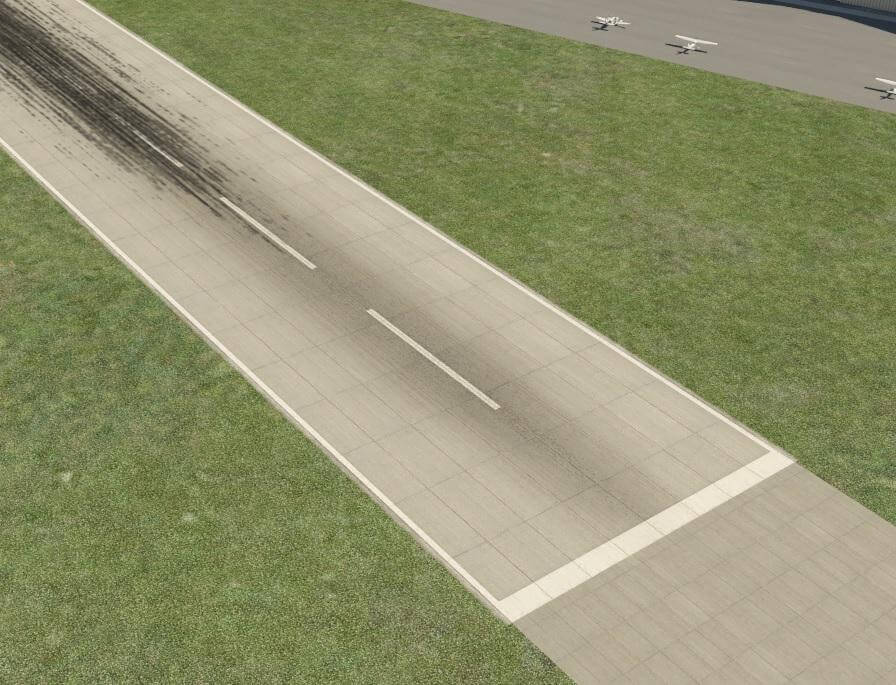
Joins for runways with shoulders should overlap up to the runway edge. (See “Correctly Forming Taxiways and Junctions“ for more information.)
WRONG |
RIGHT |
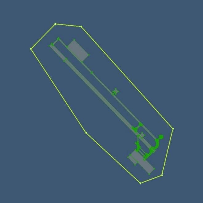
Airport Boundary
There is a fine line to walk between making the boundary too loose versus too complex. Also ensure that all runways, taxiways and ramps are completely inside the airport boundary.
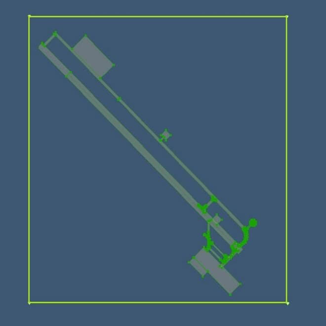
WRONG
(Too loose) |
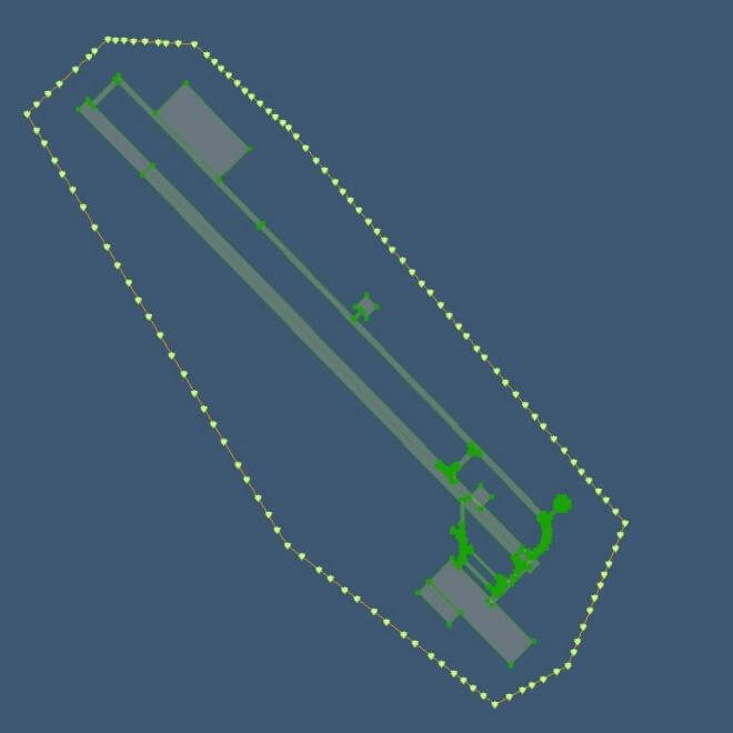
WRONG
(Too complex) |
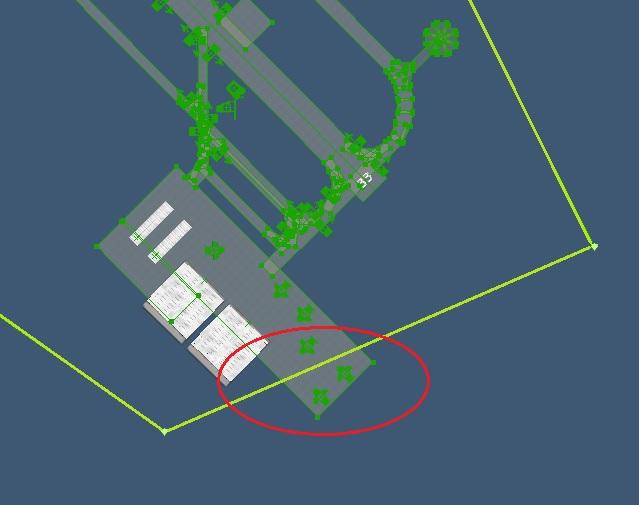
WRONG |
RIGHT |
Taxi Routes
For guidelines on how to properly draw taxi routes, see “ATC Taxi Route Authoring.”
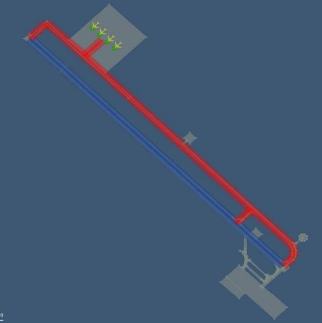
WRONG
(Hot zone extends too far) |
WRONG
(Hot zone overlays runway) |
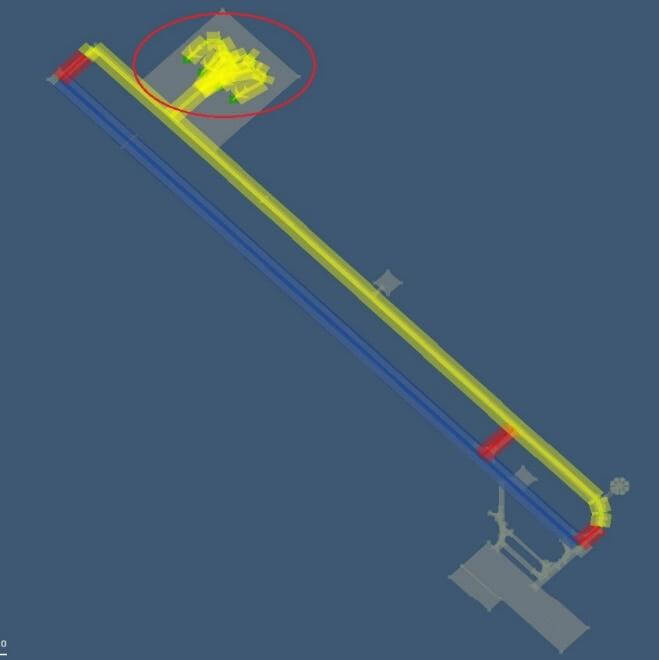
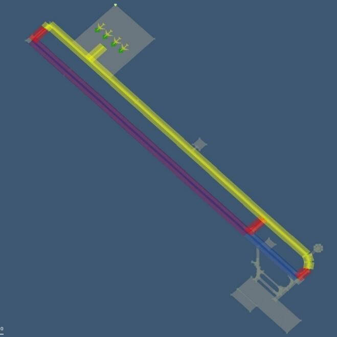
WRONG
(Micro-management of taxi routes) |
RIGHT |
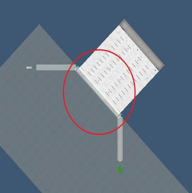
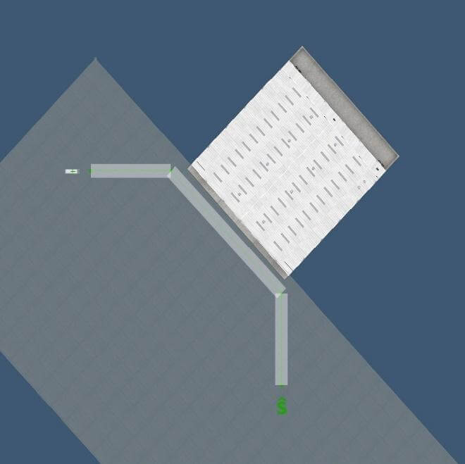
Ground Routes
Details on creating proper service vehicle routes can be found here in the WED manual.
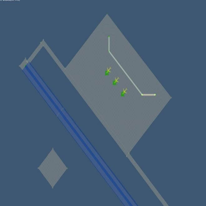
WRONG
(Route exists without parking spot(s) or destination(s) – must have both) |
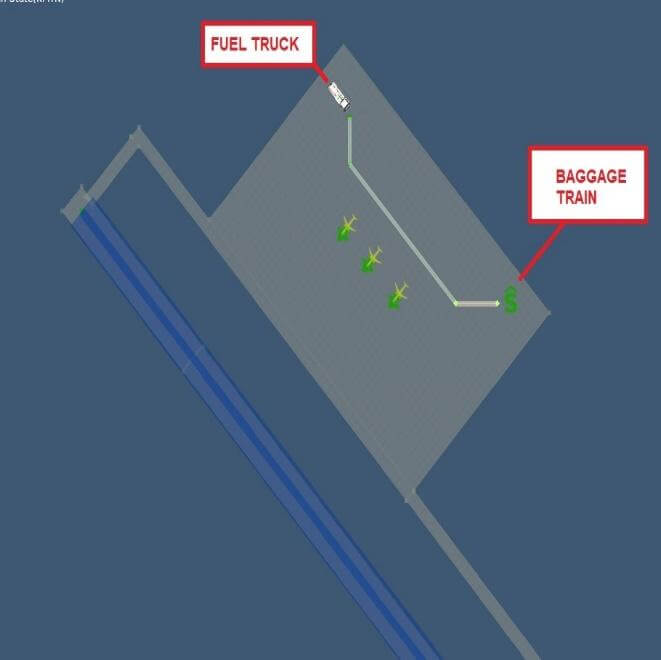
WRONG
(Mismatched parking and destination types) |
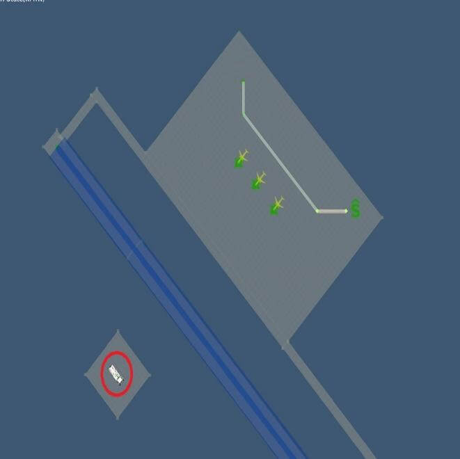
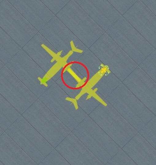
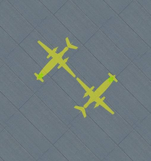
WRONG
(Parking spot(s) too far from ground route network) |

RIGHT
(Parking spots and corresponding destinations – close to network) |
Avoid route incursions as well:
WRONG
(Route is touching, or too close to, an object/facade) |
RIGHT
(Ground traffic has room to maneuver and avoid objects and facades) |
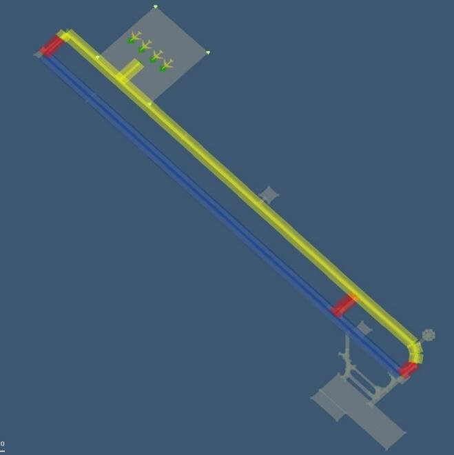
Avoid trying to micromanage the route:
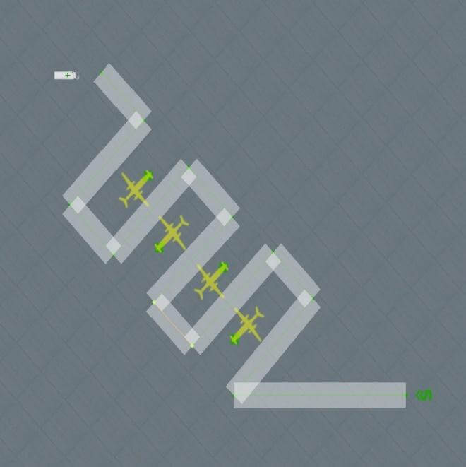
WRONG
(Micro-management of ground routes will compete with desired behavior when servicing aircraft, or parking) |
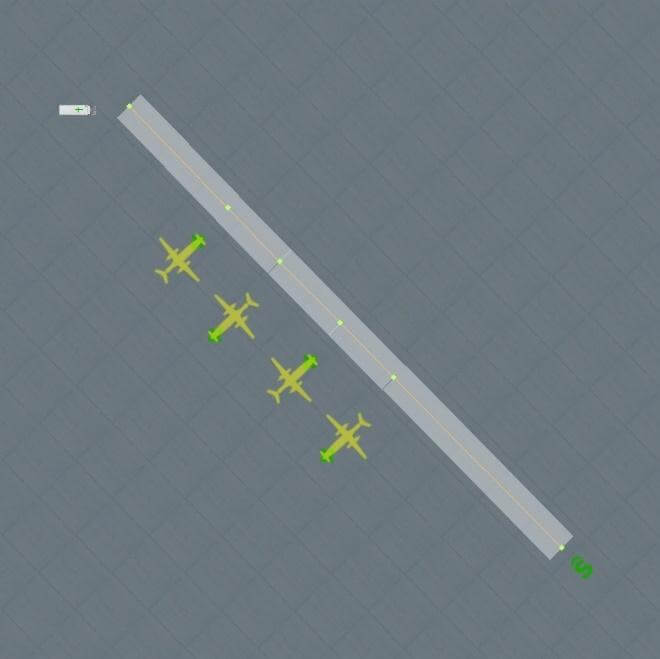
RIGHT
(Place a ground-route node near each aircraft. This is where the trucks will leave, and join the network, when providing service) |
In X-Plane
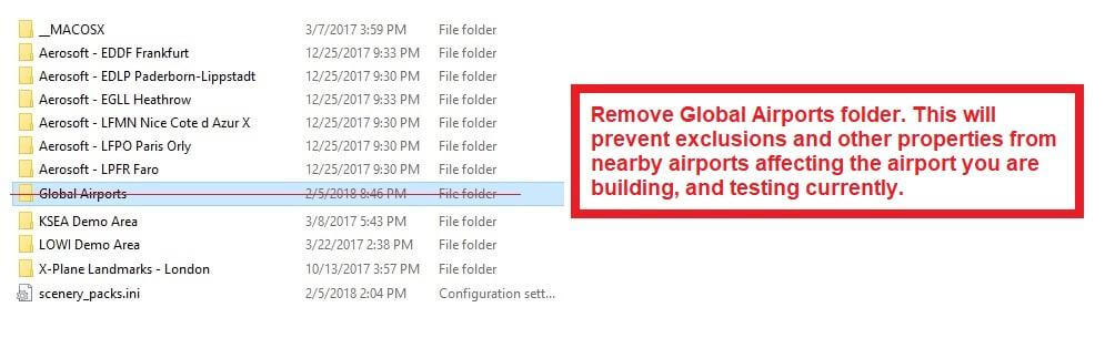
Temporarily remove the Custom Scenery/Global Airports folder when testing your airport in X-Plane.
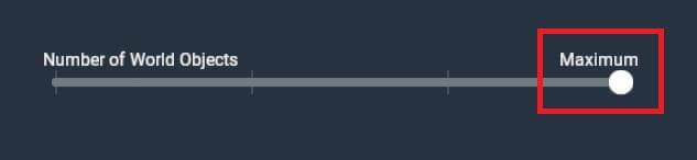
Use maximum World Objects setting when testing your airport.
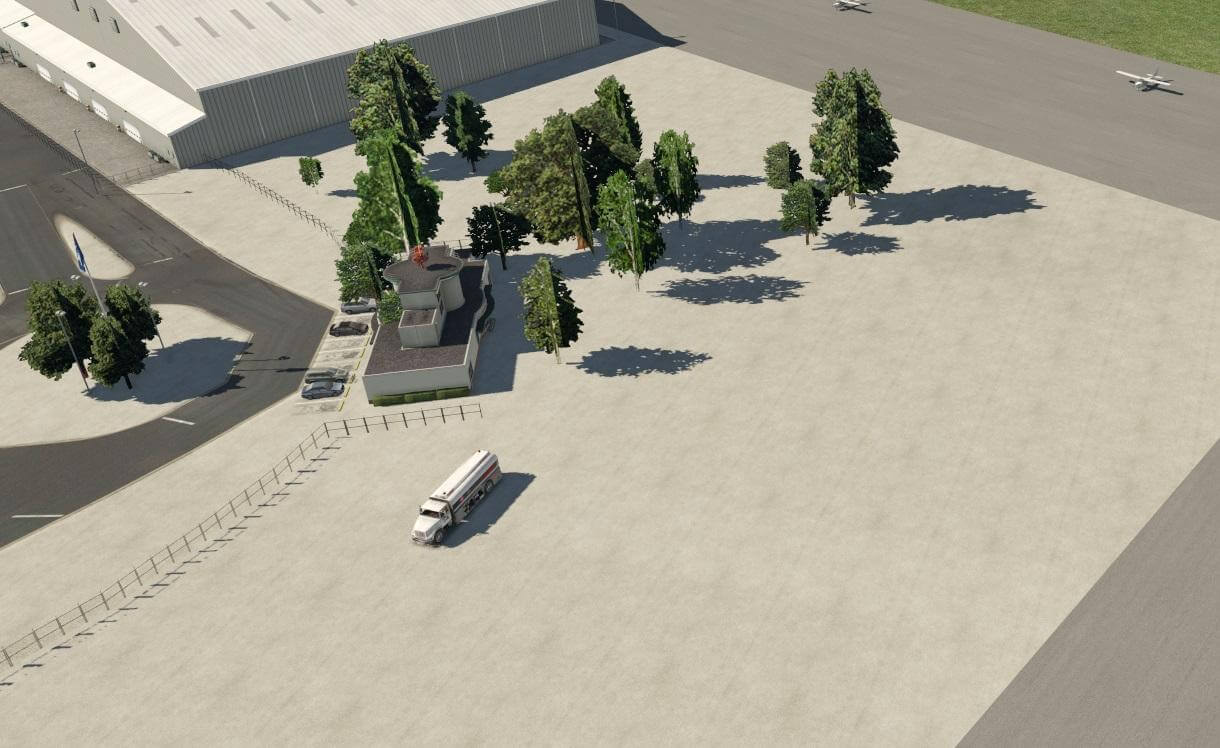
Incursions
Check for trees on ramps, taxiways or runways:
Check for road network segments on ramps, taxiways or runways:
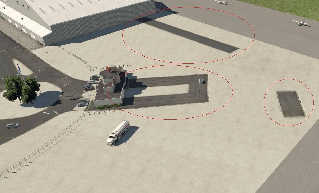
Check for objects partially buried inside other objects:
Runway Layout and Appearance
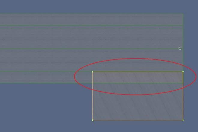
Check runway hierarchy to ensure numbers are not obscured by an overlaying runway:
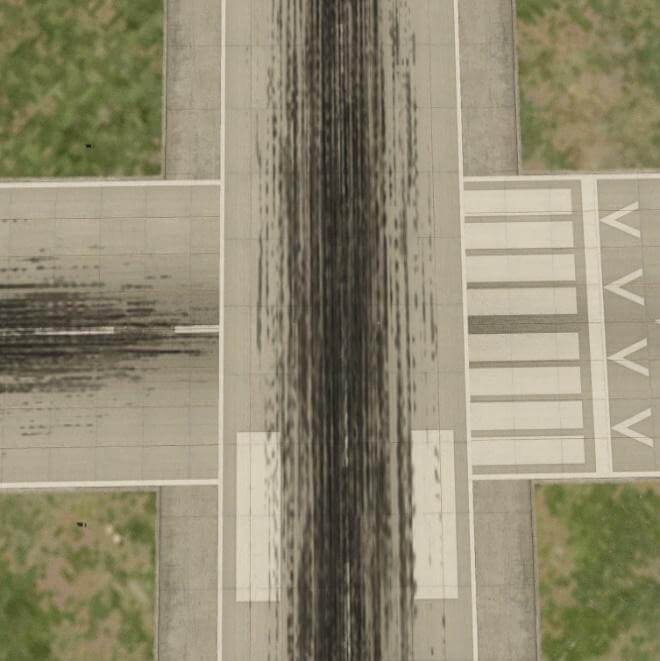
WRONG |
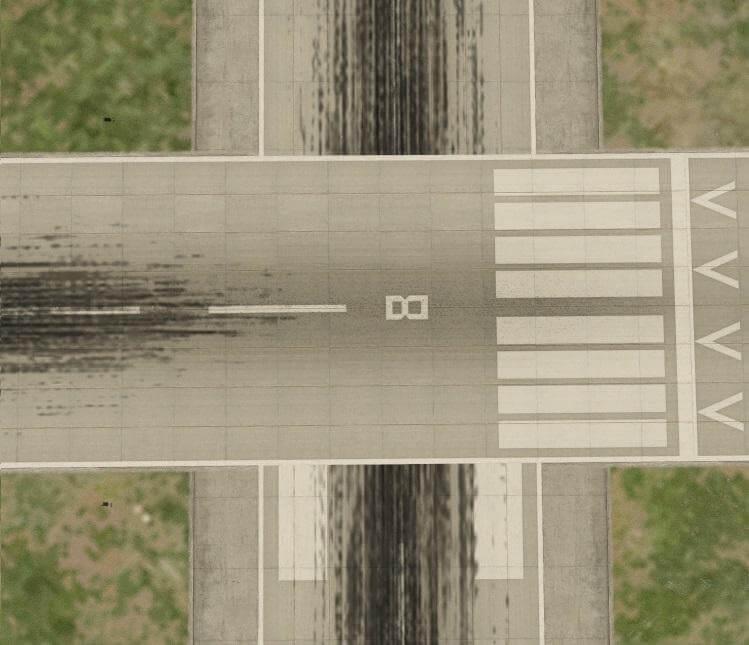
RIGHT |
Check runway numbers are present at both ends of the runway (except where runway numbers are not present in reality):
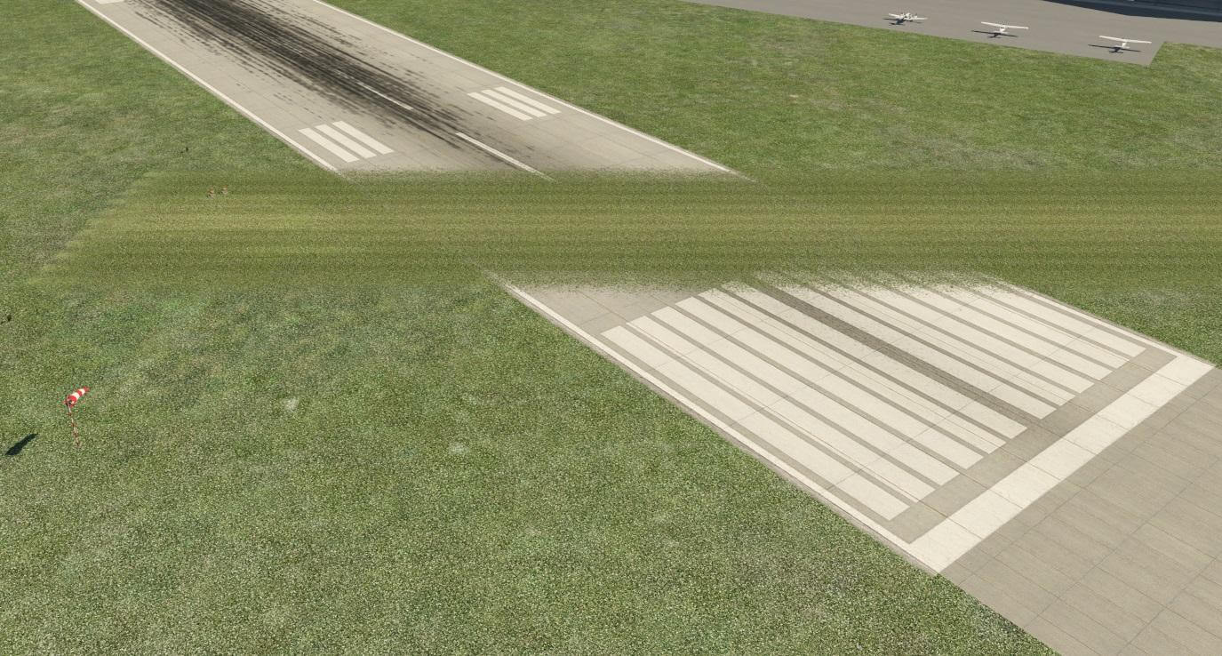
Check grass/gravel/dirt is not above pavement:
You probably accessed this page because you ran into an error message in either Plane-Maker or X-Plane, telling you your panel is not compatible with X-Plane 11. The correct fix depends on the kind of instruments you are using in your panel:
Old instrument compatibility
The following instruments are considered “legacy”. They continue to work in v10 aircraft loaded in X-Plane 11, but they can no longer be added to new aircraft in Plane Maker 11:
- GPS_BC
- GPS_GA
- GPA_HM
- FMS
- FMS_small
Note that you cannot save a panel using these instruments in Plane Maker 11. If you want to edit a panel that has those instruments in it, you need to use Plane Maker 10.
If your panel uses those, be advised that these instruments work in X-Plane 11, but will be discontinued in X-Plane 12.
New instruments
The following instruments are available for use in Plane Maker 11 and X-Plane 11:
- GNS430
- GNS430_screen
- GNS530_screen
- CDU739_screen
All of these instruments use the new navigation infrastructure of X-Plane 11 with full terminal procedure support.
Mixed old/new panels
The “copilot” checkbox of the instrument in Plane Maker’s panel editor determines whether the instrument is considered to be on the NAV1/pilot or NAV2/copilot side.
Panels using both instruments from the “legacy” and “new” category are possible, provided all instruments from the same group are on the same side. That means, you can have a new GPS on the pilot side, and an old FMS on the copilot side.
If you keep getting an error message about an incompatible instrument, check all your navigation instruments in the panel and note whether the copilot checkbox is checked. Make sure legacy vs new instruments are correctly separated by side.
A grid of 16×16 weather envelopes make up the X-Plane weather system. Each of these 256 weather “buckets” is about 1.0 degrees of longitude by 0.6 degrees of latitude, or about 35 miles or so. Custom weather can be created by modifying the METAR.rwx & winds.rwx files in a text editor. Real weather files are initially downloaded via the last tab in the Weather screen in X-Plane.
File Types
METAR.rwx
This file contains weather in METAR form at countless airports, but with a far higher density in the USA. METAR data contains weather at the surface, with cloud bases for various elevations above the airport. X-Plane can only guess at cloud TOPS and WINDS ALOFT based on this limited data from the surface.
Winds.rwx
This file loads custom winds 10,000 ft and 34,000 ft into X-Plane, so you have winds aloft for both light planes and airliners, with interpolation for turboprops that fly in between. (Note that this file is only used if global_turbulence.grib & global_winds.grib are NOT in the main X-Plane folder.)
global_turbulence.grib and global_winds.grib
Starting with X-Plane 10.50, these are GLOBAL winds-aloft files that are also downloaded so you can get winds anywhere on Earth. As with winds.rwx, these files loads winds 10,000 ft and 34,000 ft into X-Plane, so you have winds aloft for both light planes and airliners, with interpolation for turboprops that fly in between.
Modifying the Files
Now, you can make your own METAR.rwx file and winds.rwx file. First turn off the download option in the weather screen so X-Plane does not over-write your file.
To test the files that you make, tie command “sim/operation/load_real_weather” to a joystick button or key to test loading the weather at any moment to scan the files you made, or issue the command via plugin. Or just hit the “read right now” button right there in the real-weather screen.
Weather
For global weather coverage of any level of detail you like, add your own entries into the METAR.rwx file. Enter an airport ID of MDEG, followed by the longitude, latitude, and elevation in meters of the imaginary airport you just created for the purposes of setting weather at this location.
For example, if we wanted to change the weather for the South Carolina area, we would specify the area in the METAR.rwx file as: “MDEG -81.235425 34.5647 80.0”. After that we’d enter the information for our weather, such as “24031KT 2SM CLR 10/M10 A3011”.
Let’s parse the first few items in our example above. Note that X-Plane uses longitude first, then latitude; thus the location is 81.235425 degrees West, 34.5647 degrees North. Altitude is 80 meters. The wind direction is 240, with a speed of 31 knots. The visibility is 2 statue miles and the sky is clear (no ceiling). The temperature is 10 degrees Celsius and the dew point is minus 10. The altimeter setting is 30.11inHg. Continue on in this manner when you are adding custom winds or interpreting the report.
You can enter all the MDEG airports you like in a single file, to set the weather anywhere you like. If you put an MDEG airport every degree of longitude and every half degree of latitude, you will be entering about the right number of MDEG airports to get all the detail you can out of the X-Plane weather engine.
Note that if you are customizing weather for an airport that is already listed in the METAR file you will need to delete all other instances aside from your MDEG entry.
Winds
For global coverage of any level of detail you like, you can add your own entries into a winds.rwx file. If you do not have one from an older version of X-Plane 10, you can simply start a new text file. Make sure to remove the global_turbulence.grib & global_winds.grib files to avoid conflicts.
In winds.rwx, enter a wind reporting-station ID of DEG (NOT MDEG! These are 3-letter IDs!), followed by the longitude, latitude, and winds aloft, then X-Plane will set the winds aloft at this location as you enter.
Each of the numbers after the latitude represent the direction, speed and temperature. Each column of wind information corresponds to a specific altitude: 3000, 6000, 9000, 12000, 18000, 24000, 30000, 34000, and 39,000 feet. Note that you may leave a lower altitude column blank if the location is already above that altitude.
Example:
DEG -82.235 34.345 2910 3117+14 2925+08 2934+04 2924-07 2836-20 284436 284946
Let’s parse the first few items in our example above. Note that X-Plane uses longitude first, then latitude; thus the location is 82.235 degrees West, 34.345 degrees North. At 3000 feet, the wind direction is 290, with a speed of 10 knots. At 6000 feet, the wind direction is 310, speed 17 knots, and a temperature of +14 degrees Celsius. Continue on in this manner when you are adding custom winds or interpreting the report.
Enter all the DEG wind-reporting station you like in a single file, to set the weather anywhere you like. If you put DEG wind-reporting station every degree of longitude and every half degree of latitude, you will be entering about the right number of wind-reporting station to get all the detail you can out of the X-Plane weather engine.
NOTE: YOU MUST ENTER A FULL WINDS-ALOFT REPORT AT ALL THE ALTITUDES YOU SEE IN THE DOWNLOADED WINDS.RWX FILE FOR IT TO BE READ!
X-Plane will only USE the data at 12,000 ft and 34,000 ft (with interpolation in between them) but you have to ENTER all altitudes for the wind file to be scanned properly. (It’s valid to use a dummy value such as 0 for all data at all altitudes that are not 12,000 ft and 34,000 ft.)
Instruments in X-Plane are positioned based on their center position. Because an instrument with an odd width or height might have a center that is a fraction of a pixel wide, fractional instrument coordinates are allowed.
Guidelines
Here are some guidelines for positioning your instruments for maximum visual quality:
- For best quality, leave the instrument scale at 1.0. If you scale the instrument, the graphics card will blur your art. To make a small instrument, use small artwork!
- The base layer and overlay layers should all have the same even-odd status. In other words, if your base instrument texture is 57 pixels wide, your overlay should not be 54 pixels wide. All widths and heights should be either all-odd or all-even.
- If your textures are even, your instrument should be centered on a whole-pixel position, e.g. (254.0, 127.0).
- If your textures are odd, your instrument should be centered on a half-pixel position, e.g. (254.5, 127.5).
- When these rules are followed, Plane-Maker’s preview should match X-Plane when the panel is not scaled.
- If you violate these rules, the particular visual errors you get will vary based on the particular instrument, the type of alignment mistake, and possibly even your graphics card.
Test Airplane
This test airplane package demonstrates all possible instrument alignment combinations for non-scaled instruments, both correct and incorrect. Download the zip file here.
This picture illustrates the panel test:
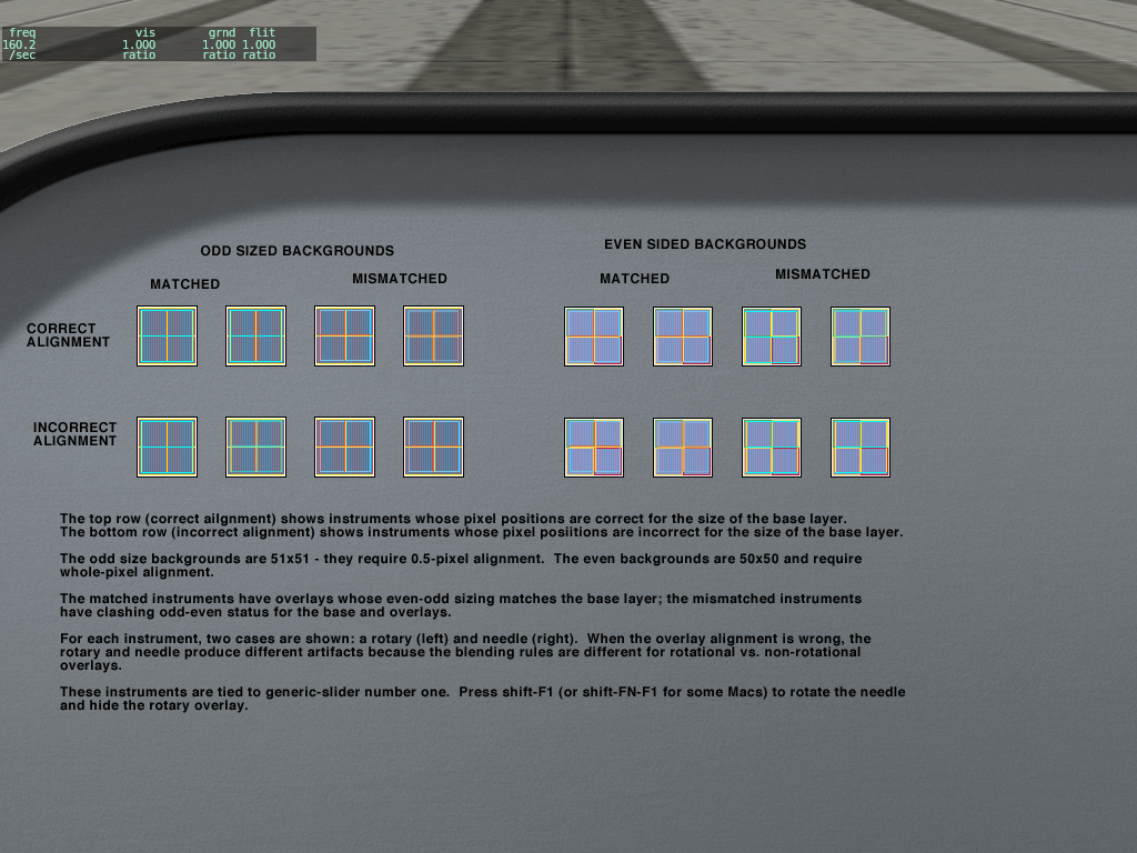
Some notes:
- When an instrument is misaligned, there may be no visible error, a full pixel error, or in the case of rotating panels, blurry pixels.
- The error may be different for each layer of the instrument.
 This picture on the left is from Plane-Maker editing a 3-d panel. (That’s why it is just a “packed” set of instruments with no background; this panel is used as a texture for a 3-d cockpit – each instrument is UV-mapped into the right location.)