This goes into the bucket of “weird X-Plane behavior”: X-Plane will try both PNG and BMP file extensions when opening images, no matter what is in your file. How we got to this state is, at best, confusing.
Originally, most X-Plane image files did not contain a suffix. So an ENV file contains “grass” and X-Plane would change that to grass.bmp.
Then we added PNG support. X-Plane would try grass.png and then grass.bmp. In this case, not having the extensions turned out to be handy — authors could simply bulk-convert their images and go on with life.
With most new scenery system files, the extensions are a lot more rigid:
- The extension appears in the referencing file.
- The sim only tries that extension.
- If the format doesn’t match the extension, it’s an error.
So if you want a DSF file to reference a facade, it’s buildings.fac and if that .fac file is actually a forest file, it’s an error. The sim won’t try to decide which is more correct, the header of the file or the extension, it will just go “you’re nuts” and bail out.
But (for historical reasons) images are an exception. Keeping with the “any extension goes” theme for images, X-Plane will actually try PNG and then BMP versions of your file. The extension has to match the format…that is if you call your bmp foo.png X-Plane won’t load it at all.
We have PNG as our primary image format and BMP for backward compatibility. But it’s imaginable that we could have DDS and PNG both as primary formats — PNG for images that need lossless fidelity and DDS for images where compression is acceptable. In such an event, X-Plane’s tendency to try every extension means authors can bulk-convert from PNG to DDS (making their packages load faster) and go home happy.
Jonathan Harris suggested I look into .dds as an image format for X-Plane. I think he’s got a good idea.
First, what is DDS? It stands for “direct draw surface”, but as a file format, it’s basically a file whose structure is the same as the memory layout for a texture in DirectX. It’s a simple image format but it does two useful things for X-Plane (or any other 3-d application):
- It can contain compressed images using the same compression OpenGL and DirectX use (DXT compression).
- It can contain mipmaps – smaller versions of the same image.
Now before things get out of hand, using .dds files in X-Plane would not mean converting X-Plane to use DirectX!! .dds is simply an agreement about how to arrange a file. You can easily write code to load a .dds file into an OpenGL application, and that is what we would do.
There would be three fundamental benefits to using DDS files:
File size on disk (and download).
PNG is a losslessly compressed file format. This kind of compression (the internal algorithm used by PNG is the same as ZIP files) preserves the image, but the reduction in image size is a function of how “simple” the image is. Images with a lot of detail and high frequency information (rapid changes in color) do not become much smaller than the amount of VRAM they use when compressed in a PNG. A lot of the terrain textures we use (4 MB in VRAM) are still 3 to 3.5 MB on disk!
By comparison, the texture compression used by OpenGL is lossy – the image looks worse. But the image is reduced by a factor of 4 to 8, every time. So one of these images (4 MB in VRAM when uncompressed) would be 1 MB with S3TC compression (available in a DDS file). Even for very simple PNG files, you rarely see such a reduction in size, so .dds files would be smaller, meaning faster updates and downloads.
(Another thought: if a PNG file is smaller than its VRAM requirement, it means the PNG file has lots of areas with the same color. This means the PNG file is WASTING VRAM! We encourage our artists to make use of every little pixel in an image, and this means that PNG files that are well-created for X-Plane tend to get relatively little benefit from PNG’s internal compression.)
Load Time
Image load time is a significant factor in X-Plane. There are several reasons why DDS files could load a lot faster than PNG.
- The actual DDS file is smaller – less data to load and process means faster performance.
- Because the DDS file can contain smaller copies of the image, X-Plane doesn’t have to load a huge image and reduce its size using the CPU – it can just load the small version in the file.
- When compressed textures are used (and they almost always should be, see my previous blog post) it takes CPU power to compress the image, slowing down load. A DDS file containing a compressed image can be sent directly to the card!
Image Quality
Now one is a little bit tricky. First, please review my previous blog post, which argues that texture compression is the best way to maximize VRAM. A DDS file will look better than a PNG file when texture compression is on. Here’s why:
The S3TC compression formats specify an EXACT way to “uncompress” and draw a compressed image. But there are MANY possible ways to compress the image. Remember that S3TC is a lossy compression – the compressed image is only an approximation of the original.
Well, it turns out that algorithms that find the best approximation of an image using S3TC are slow. So we can’t use the highest quality compression inside X-Plane when compressing PNGs for the graphics card – it would be too slow.
But the image in a DDS file is already compressed — because someone else has compressed it when creating the scenery. When converting the scenery from PNG to DDS that author can use a very slow, very high quality compression algorithm to make the DDS files. It might take 12 hours to convert the entire package from PNG to DDS, but who cares? It’s something you do once and then everyone enjoys better looking images.
In other words, because the compression is done ahead of time for a DDS file, a higher quality algorithm can produce better approximations of the original images. Since we want to use compression anyway (to optimize our use of VRAM) this is a good thing.
When is DDS not appropriate?
Any time an image must not be compressed, DDS is inappropriate, and PNG is best. There are three basic cases in X-Plane where we avoid compression (see my previous blog entry for the real examples):
- Any time we need to preserve tiny detail accurately, like lettering and text.
- Any time the alpha channel needs to be smooth.
- Any time a texture is magnified so large that small color changes between two pixels is noticeable. (For example, compressing the color washes used for the sky make obvious artifacts.)
DDS wouldn’t replace PNG, it would augment it.
Speaking of compression, X-Plane doesn’t compress all textures…even if “texture compression” is on, we leave uncompressed certain textures that are flagged. A rough list:
- Most textures in the sky, like clouds and color stripes, have a lot of alpha and get wrecked by compression. They get exempted.
- Anything related to the 2-d panel, maps, and the UI get exempted.
- Some of the overlays like rain and snow, smoke puffs, and lights.
- Taxiway signs get exempted…S3TC does a number on letters and numbers.
Try this experiment: take three screen-shots (use ctlr-; to get a stable, clear view), with these settings:
- Extreme res, with tex compression
- Extreme res, without tex compression
- Very high res, without tex compression
Now consider the effect on VRAM. Each time you go down a texture resolution level, tex sizes are cut in half, and you cut VRAM use by a factor of 4.
If you use texture compression, you cut VRAM use by a factor of 4 for textures with alpha and a factor of 6 for textures without alpha. (Some textures are unaffected because they are internally marked as “never compress”.)
Now look at your visual results. I would argue two things:
- At extreme res, turning off texture compression doesn’t make the image a whole lot nicer. (It does make the machine a whole lot slower!)
- Texture compression is a lot nicer than going down a res level.
I suspect that if your machine can’t handle extreme res, you can get similar results running the whole experiment down one notch.
I think that almost everyone who has a limited machine is running with texture compression these days – we default with it on and it helps fps. I would only argue that any users who are running with a huge machine and compression off might consider turning it back on. It doesn’t hurt much and it does make the machine run faster.
(Even if you have a ton of VRAM, X-Plane can be limited by how fast texture data transfers from VRAM to the GPU, within the card. Texture compression helps this.)
Austin and I have this debate over and over when we find a case where third party content doesn’t work right with X-Plane (but did in the past due to X-Plane’s permissiveness):
- If we code X-Plane to work around the problem, users get to enjoy the scenery, and authors will never fix the problem.
- If we code X-Plane to abort, users get grumpy, and authors fix the problem real fast.
What to do? A few versions ago I implemented the scenery warning system (the spanking system) to try to get the best of both worlds. I just discovered another problem that illustrates how this works well.
Before WED some authors made apt.dat 850 layouts by hand using a text editor, and sometimes they forgot to include a closing code on their rings and chains. I can hardly blame them, writing an apt.dat file by hand is very difficult, and I am impressed (and grateful) that they did this.
The apt.dat 850 spec is clear:
- Pavement chunks (line code 110) must comply with the following:
- Chunks MUST terminate in a segment point of type 113 or 114.
- Linear features (line code 120) must comply with the following:
- Linear features must terminate in a point of type 113, 114, 115 or 116.
- Linear features do not need to be “closed”.
- Airport boundaries (line code 130) must comply with the following:
- Boundaries MUST terminate in a segment point of type 113 or 114.
- Boundaries must be a closed loop and cannot contain holes. As with pavement chunks, the airport boundary cannot overlap itself.
So, you must have one of the closing codes at the end of a boundary, taxiway, or line. But X-Plane 860 doesn’t check this and simply assumes a “closed ring” if no code is provided. With X-Plane not telling authors, the authors never caught this mistake.
So now that I know about this (and now that X-Plane needs the end codes to be right, due to other bug fixes) it’s time for the spanking system. In future versions of X-Plane:
- Custom scenery packages with no ending code on a polygon block will automatically be adjusted to be “ring”-type on load-in, for compatibility with X-Plane 860.
- A detailed message will be printed per polygon in the log.txt file.
- A single alert box will be shown to the user saying “there is a problem with the custom scenery pack XXX”.
The idea is for the dialog box to walk a fine line between being unobtrusive enough for users and annoying enough for authors.
Back in X-Plane 7 the default scenery location was the “Earth nav data” folder of the Resources folder. Custom scenery went into packages in the “Custom Scenery” folder, just like now.
In X-Plane 8 we introduced the concept of a “default scenery” folder in the resources folder. The default scenery folder acts exactly like the custom scenery folder, in that it holds scenery “packages”, but it has two special properties:
- Packages in this folder have lower priority than any custom scenery package.
- It is in the resources folder and is therefore the turf of Laminar Research and our updater — the Custom Scenery folder is for third parties.
Okay that’s not really a special property, more of a convention. But the main idea here was to remove special cases from the scenery system…in X-Plane 8, all scenery comes in packages, no matter what it is and who ships it.
Scenery comes in packages, period. Repeat it like a mantra.
The original X-Plane 8.0 still installed legacy ENV files into the Resources/Earth nav data folder (but installed DSFs into a package). X-Plane 8.20 (when we shipped full DSF scenery) installs everything into packages, as will all future versions of X-Plane.
X-Plane 8 still looks in “Resources/Earth nav data” as a last resort. But this is going away! Future versions of X-Plane will only look for real scenery packages in the “Custom Scenery” and “Default Scenery” folders.
What does this mean to you? Almost certainly nothing…but…
- If you are an author and your scenery needs to be installed into the resources/Earth nav data folder, fer cryin’ out loud, please put your scenery into a custom scenery package. It takes about 5 seconds and will make life easier for you and your users.
- If you are a user and you have been moving files into the the resources/Earth nav data folder, please don’t do this! Learn how scenery packages work and put whatever you’ve been moving into a custom scenery pack. You’ll find things much easier to deal with.
I’ve posted WED beta 2.
The executive summary regarding split beziers: use beta 2 and re-export your layout and you should be more or less fine. There is no need to avoid them anymore.
Also a note on the source code: I will update the source code base of WED about every two weeks during beta, or whenever anyone asks me to post latest, whichever comes first. If no one asks, this will mean the source code is slightly behind the latest binary beta, but I think we can live with that…it takes a while for me to ball up and post the source code. (Again, if you want the current source code now, you are absolutely entitled to it – send me an email and I’ll post ASAP.)
I will make sure the code is updated when WED goes final, of course I expect a new binary beta about every 3 or 4 days until we get it mostly shaken out.
A thread on X-Plane.org referenced whether program should be labeled beta. I am definitely guilty of leaving some of my old programs labeled as beta, when I should have done one more build and marked them as final. I will try to avoid doing this in the future! But WED is definitely beta material right now.
Thanks to everyone who reported bugs in beta 1 – the feedback was very high quality. The new download’s README contains the list of bug fixes.
Posted in Tools
by
Ben Supnik |
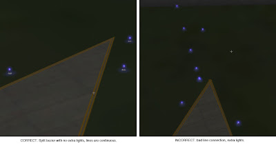
In my previous post I described a bug where, when we have a split vertex in an apt.dat layout, X-Plane would draw taxiway lights all over the place. Fortunately, there is a workaround.
Remember that a split vertex is represented as two or three colocated vertices with one or two zero-length segments connecting them. The bug is that zero-length segments cause lights and lines to go haywire.
The fix is therefore simple:
- Programs that write apt.dat files can simply set the attributes on the zero-length segment to none.
- Future versions of X-Plane (with a real bug fix) can join taxiway lines even when there is a zero-length “break” in the attributes.
This picture shows the results – a split vertex with no attributes on the zero-length segment.
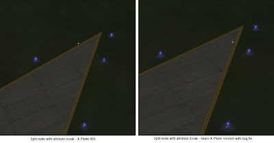
The next WED beta will automatically export split vertices this way – there will be no need to patch X-Plane or change your WED layouts.
In my previous blog post I defined a split vertex in an airport layout and described how they can be simulated in an apt.dat pile using multiple points.
Now that WED is in public beta and people can easily make split beziers, many have noticed the “split bezier” bug in X-Plane 860:
This is a vertex that is split…on the left you can see what it should look like – on the right you can see what it does look like. There are two problems going on:
- The taxiway lights have gone crazy at the split vertex. (This is what everyone sees.)
- The taxiway line is a bit jumbled at the split vertex too.
It should be noted that this bug will can also happen for any vertex (even unsplit) in rare occaisions due to interactions with the mesh. Same symptom, same buggy code, different cause.
The good news is:
- There is a workaround that will make the lights look correct and the lines acceptable in X-Plane 8.60.
- The workaround will be implemented inside WED – no need to change anything.
- When X-Plane is fixed, it will make the lines correct too.
In my next post I’ll describe the fix and what the results look like.
(This blog entry explains the background of split beziers – the next parts will explain the bugs that they cause and the workarounds.)
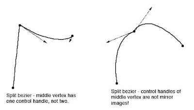
In apt.dat terminology, a split vertex is any vertex of a polygon where the control handles on either side of the vertex are not exact mirror images. (When there is only one control handle it is therefore by definition split!)
You need a split bezier any time you want to:
- Have a sharp corner between two curves and control the tangents of the curves or
- Have a sharp corner between a truly straight segment and control the curve of the next segment.
Split Beziers and apt.adt
Now here’s the rub: the apt.dat format does not allow for split beziers – each curved point has only one control handle – the other is calculated by x-plane by mirroring…thus no vertex can ever be split.
(This is due to a total lack of brains on my part when working on the apt.dat format, which is quite embarrassing considering how long I spent thinking about it.)
The Hack
There is a way to simulate a split bezier: if you use zero-length segments (that is, multiple points on top of each other), you can create a shape that works as if it is split.
In its simplest, a split bezier can be created by using 3 vertices.
- The first vertex uses the control handle of one side.
- The second vertex is not curved.
- The third vertex uses the control handle of the other side.
Why does this work? Well, a bezier curve between a curved point and a straight point has zero length if the two points are on top of each other. So what we’ve done is inserted two zero-length segments. The result of this mess is that the control handles on either “side” of this cluster of points can be different!
Is the second point really necessary! Yes! The reason is this: if we simply had the first and third point (two bezier points with different control handles), X-Plane would draw a loop from the first to the second. Remember: two colocated points with ONE control handle form a zero-length curve, but two colocated points with TWO control handles form a loop.
(To see this for yourself, just draw some examples in WED or photoshop. 🙂
Line Continuity
There is one more wrinkle we have to add to the puzzle in order to understand how this works, and what the pitfalls are: line continuity.
A bezier path (taxiway edge, linear segments, etc.) is made up of one or more bezier curves. Each curve has zero or more attributes.
When X-Plane draws the actual taxi lines and lights, it looks for continuous adjacent bezier curves with the same attribute and makes sure the linkage between those attributes is correct.
(This linkage is computed separately for each type of property. So if you have taxiway lines on two segments and lights on one, the taxiway lines will still link!)
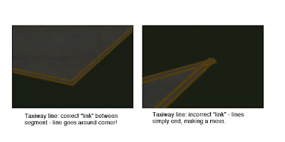
The picture above shows a correct vs. an incorrect link. When dealing with unsplit beziers and non-curved points, linkage is pretty much automatic, it just works.
But there is a pitfall to our above hack for split vertices: we have three points on top of each other. They must all have the same attributes in order for linkage to work. A “break” in the continuity of the line for one of the zero-length segments still counts as a break in linkage. The picture on the right was produced by creating a split bezier and removing the double-yellow-line attribute from the second of three vertices.
In my next post I’ll explain the bugs that this causes in X-Plane 8.60.


