Propsman caught something:
…is modifying the value of a batch of ATTR_light_level tris comparable [performance-wise] with toggling the state of a backlit generic instrument? Instinct tells me that you must have the latter more streamlined than the former, but maybe not?
He is right: in the current implementation, ATTR_light_level is probably a bit more expensive than using generic instruments. This may not be true in the future though.
- The generic instrument code is pretty tight.
- Right now ATTR_light_level sometimes has to adjust shaders, which can be expensive.
- In the future, ATTR_light_level has the potential to be very heavily optimized, while the generic instrument code will always be CPU based.
But to put it in perspective, all instrument drawing is slow compared to scenery drawing – in the scenery world we draw 50,000 triangles of identical OpenGL state in a row, and modern cards do that very, very well. In the panel, we have to put in a lot of CPU time to figure out how to draw each quad or tri-strip. Fortunately you probably don’t have 50,000 individually programmed flashing lights in your panel. Heck – there’s “only” 3608 datarefs published by the sim.
Perhaps other questions are important when picking ATTR_light_level vs. panel texture:
- Which is more useful: to be able to have several variant images and variant images that are not “lights” (this is only possible by generics) or the ability to vary the light level gradually and not just have on or off (this is only possible with ATTR_light_level)?
- Which is simpler to author given the rest of the panel?
In other words, it’s all pretty “slow”, but fortunately “slow” isn’t that slow. If your light has to blink, you may want to pick what looks best and is straightforward to author.
In my previous posts I have tried to explain the difference between commands and datarefs, and when you might use each. To review:
- A dataref represents information. You can always read it, and you might be able to change it.
- A command represents an action. You can always invoke the action, but you can’t tell if it worked without looking at a dataref.
So…why is there so much overlap and duplication?
Dataref Vs. Dataref
There is duplication in the datarefs because we don’t delete old datarefs when we add newer, improved ones. The old datarefs stay in place to keep old plugins working. Here are a few reasons why we’ve added new datarefs:
- The
cockpit2/ and flightmodel2/ sections were added as a new, simpler, easier to use interface for authors in version 9. (Read more here and here and here.)
- In some cases, the old dataref was a bit-field while the new one is a simple integer. While plugins can use bitfields, modelers cannot animate using bit fields.
- In some cases, the old dataref did not represent a clean view of the data. Some old datarefs exposed X-Plane internal structures that are not appropriate for long-term use.
To see this in action, let’s look at the autopilot. How many ways are there to set the autopilot mode?
sim/cockpit/autopilot/heading_mode. This is the original heading mode, and it is marked deprecated, because it exposes a bunch of internal X-Plane autopilot values.sim/cockpit/autopilot/autopilot_state. This is the ideal autopilot dataref for plugins. It provides all functions, but since it is a bit-field it is not useful for authors.sim/cockpit2/autopilot/heading_mode. This is a clone of the original heading_mode into the cockpit2 domain. Honestly I am not sure how it got there – I know it was me who put it there, but it sure is a dumb idea; the original dataref is deprecated, so it was stupid of me to duplicate it!sim/cockpit2/autopilot/heading_state. This is coming in 930 and provides a heading-state enum set appropriate for authors…basically an enum that matches the two heading bits of the autopilot_state dataref that programmers were using.
How do you sort through this? Three rules of thumb:
- Try to use
sim/cockpit2 and sim/flightmodel2 when possible.
- More recent datarefs are usually better.
- Use the most useful dataref you can find.
Commands Vs. Commands
Sometimes there is some duplication of commands, e.g.
sim/engines/carb_heat_on                           Carb heat on.
sim/engines/carb_heat_off                          Carb heat off.
sim/engines/carb_heat_toggle                       Carb heat toggle.
Here it’s a lot more obvious why there are multiple commands: they affect the carb heat in multiple ways. Typically this is done because commands are mapped to joysticks and other USB hardware; some hardware generates a button press when a command is toggled, but some hardware generates two commands, one for the off and one for the on position.
The rule of thumb is: use the command that gives you the action you want.
Commands Vs. Datarefs
Very often there will be a command and a writable dataref. Typically we need them both:
- The command is needed to let users set up their joystick and keyboard.
- The dataref predates version 9 – writing it was the only way to invoke an action.
Newer datarefs are more likely to be read-only, as we put new “changing the sim” functionality into commands. To go back to our autopilot example, we have on command: sim/autopilot/heading that lets us arm heading mode. This command is probably preferable to any of the datarefs for changing the autopilot state.
My
previous post discusses writing to a dataref. vs. actuating a command in more detail.
There is a lot of overlap between the datarefs and commands; very often there is both a dataref (telling information about some part of the sim) and a command (which takes action to change some part of the sim). Which should you use?
Here are some general guidelines:
- If you want to set up a joystick or keyboard, you have to use a command. The joystick and keyboard configuration dialog box lets you associate actions with a keystroke or button press, not information!
- If you need to show the status of a system (E.g. “is the landing gear down”) use a dataref. I will cover this issue in more detail in part 3, but basically only datarefs show you information.
The ambiguous case is whether to use a dataref write or a command to change a system when both exist.
- If there is a command that exactly does what you want to do, prefer the command over the dataref. For example, it is better to arm the autopilot using the commands than the datarefs. Changing the autopilot state often involves changing a lot of variables at once in complex ways. When you issue the command, that work is done for you, correctly, every time.
- If the command is not really suitable for your purpose, use a dataref. For example, to change the engine throttle position, do not use the command
sim/engines/throttle_up to move it up “a little bit.” Use the dataref sim/cockpit2/engine/actuators/throttle_ratio to set the throttle to the precise position you want. The throttle-up command exists so that users with no joystick or mouse wheel can fly with the keyboard by pressing the F1-F2 keys (bound to throttle-up, throttle-down). It is not meant to precisely control the throttle position!
(I will discuss why there are so much overlap between commands and datarefs in part 4.)
In order to understand the vanishing point in Plane-Maker, we first have to look at field of view and the process by which X-Plane simulates a 3-d world on a 2-d monitor.
Field of View
Field of View is the angle that you get if you go from the left edge of your vision to your eye, then back up the right edge. In the case of a monitor, we can calculate this (depending on how far back I am sitting). For example, my 19″ LCD is 14.8 inches across the top; to have a 45 degree FOV I need to sit about 17.8 inches away from the monitor.
X-Plane lets you set the field of view. Imagine that you were sitting in front of a window on an airplane. As you put your face closer to the window, you can see more of the world outside. Effectively you are increasing your field of view. X-Plane works the same way – turning up the field of view parameter will increase the amount of “stuff” you can see.
Where Is The Horizon?
So where is the horizon? The answer is: it depends. Assuming you are looking straight forward, the most logical place to put the horizon is exactly half-way up the monitor. And this is what X-Plane does in any external view.
As you rotate your head up and down, the center of your vision changes relative to the horizon. But if you simply move your head up and down, the horizon doesn’t move. This is due to parallax. The closer an object is, the more it moves as you move your head. This is what lets me look “over” the dashboard of the car by sitting on a phone book: as my head goes higher, the dash board (close) appears a lot lower but the road (far) appears only a little bit lower. The horizon (very, very far away) doesn’t move at all.
This effect works in X-Plane. Try moving the view point up and down in a plane with a full 3-d cockpit, like the Cessna 172. As you move your head up and down, your ability to see the runway out the window will change.
2-D Panels
Things get weirder when we have a 2-d panel. A 2-d panel is sort of a flat image of what a 3-d cockpit might look like. We need some kind of correlation between the 2-d world and 3-d world…that is, where does the horizon appear through this 2-d panel. That location is the “vanishing point” in Plane-Maker.
Here’s where things get strange: what do we do when we scroll the panel? Do we move our head or tilt our head? The answer is: neither. Scrolling the 2-d panel simply scrolls the “window” within the 3-d world that we look through. This has the effect of moving the horizon (by the exact number of pixels the panel scrolled) without rotating your view point.
This isn’t necessarily the best way to scroll the panel, but it looks pretty good, and anything we do with 2-d panels is going to be an approximation.
And Now The Bug
Of course, there must be a bug in here somewhere…these blog posts are usually the result of an investigation into an edge-case in the sim. In X-Plane 930b6, we pick a vanishing point based on the 2-d panel when we are in 3-d cockpit mode.
Why would we do such a silly thing? Originally it was to keep the horizon from jumping when there is no 3-d cockpit object. This behavior is okay in that case, but here’s how we get burned: if the 2-d cockpit has to scroll, the vanishing point might be off the top of the screen. Authors who have made very large 2-d panels and separate 3-d cockpits see this as the 3-d viewpoint being stuck straight down. What’s happening is the vanishing point (and thus the center for the mouse) are off the top of the screen.
For beta 7 I am fixing this:
- If there is a 3-d cockpit object, the vanishing point will be the center of the screen, which is almost certainly the right thing to do for a real fully 3-d view.
- If there is no 3-d cockpit object (but instead X-Plane’s default of the 2-d panel floating in space) the vanishing point will match the 2-d view, but taking the default scroll position into account. This should keep the horizon at a reasonably sane point.
As a final note, it is possible to specify a 3-d panel without a 3-d cockpit object in X-Plane. Don’t make a plane like this. It’s a silly thing to do!
The code that decides what parts of the plane get drawn in what views is, to put it midly, byzantine. The code evolved, and in this process became more complex and convoluted.
One of the side effects was a series of bugs that couldn’t easily be fixed – typically it was a case where some new piece of code had to do some drawing, but the decisions on how to draw were being made by legacy code that had no business making those decisions.
So for beta 6 I rewrote that code.
Here’s what this means: if your airplane starts showing the wrong “stuff” in various views in beta 6, please send me the plane, and a description of what it does in 922 and 930b6.
The risk is that I may have missed some of the quirkier behaviors that 922 was capable of. My goal is to have 922’s behavior, but with clean code. So if things changed, please let me know!
X-Plane 930 beta 4 will be out real soon, and it has a somewhat significant new instrument feature: all instruments (not just generic instruments) can have additive lighting.
But wait – what is additive lighting? Additive lighting is the basic equation X-Plane uses for “lit” stuff. Basically it says that the _LIT texture is added to the daytime texture to simulate the effect of an object that reflects sun light and emits its own light. Here’s a
more detailed description.
It used to be that the _LIT textures for instrument overlays were used instead of the daytime ones at night. Generic instruments introduced a new lighting mode, “back-lit”, where the LIT texture is added to the daytime texture. This lets you make an instrument that has a light behind it to illuminate the markings at night.
In particular, when an instrument is back-lit, the amount of LIT texture added in is a function of the instrument light levels (the pilot can turn this up and down) while the amount of day time texture is a function of the sun and spot light shining on the area.
Originally I did not want to extend the legacy instruments to support back-lit lighting. What finally made me change my mind was the amount of detail in some of the standard mechanical instruments. As an exercise, I converted the six pack and nav instruments of Max’s default Cessna to generic instruments.
The conversion required a lot of new (and very weird) datarefs, some esoteric extensions to the generic needle instrument, and it lacked some of the finesse of Austin’s built-in instruments. All of these problems stem from one limitation: the animation action of generic instruments cannot be nested.
(Of course there is a practical consideration too – for an author with legacy instruments, rebuilding with generics takes time. Typically it took about 4-6 generics to model each built-in instrument in the six pack. The conversion only took me about eight hours, but I have access to the source code of the built-in instruments, a luxury authors would not be able to leverage.)
So in the long term, I am at least investigating the notion of nested animations and movements for generic instruments; I think that this would be the final flexibility needed to model just about anything with generic instruments.
But for the short term, you can back-light your built-in instruments; just set the lighting mode to “additive” and create the LIT textures.
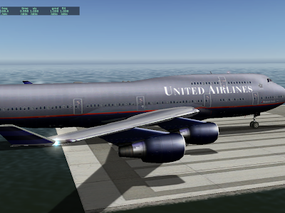
A number of users have commented that the X-Plane 930 betas looks “shinier” than before. There are actually two separate features going on :
- Separate specular hilights. Specular hilights are bright areas on the plane that simualte the refelction of the sun on a shiny surface. X-Plane has had specular hilights for a while (available by the “shiny” check-box in Plane-Maker or ATTR_shiny_rat for an OBJ). What’s new is: while previously the hilights were modulated by a texture, they are now independent of the texture. This change means that even a black surface can look shiny now. Before the black surface would “tint” the hilight black, making it invisible. Now we can have a white hilight on a black surface for a glossy look.
- Per-pixel lighting (when shaders are on). Before the lighting calculations were performed on each vertex on a model, then the color from the lighting was interpolated. The problem with this is that if there is a very local lighting effect (like a specular hilight) that is smaller than one triangle, you can’t see it (since we can only see the lighting at far apart vertices). With 930, the lighting calculations are done per pixel, making the lighting effects look smoother.
Here we have the default 747, as of 922. It’s a little bit tricky to tell what’s going on because the texture has been painted to look like there are lighting effects. But the white “specular hilights” on the engine nacelles are due to the sun position. Lighting is per-vertex and specular hilights are not separate.
Next we have the same plane in 930 without shaders:
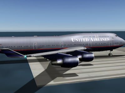
Note the increased brightness on the nacelles and fuselage. What’s happening is the hilights are no longer modulated by the texture, so they show up a bit more.
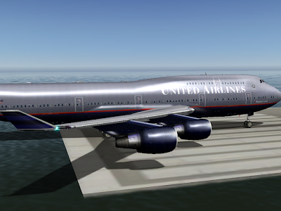
Finally, the plane in 930 with shaders. Now the hilights look smoother and much brighter. This is because the hilights are calculated on a per-pixel basis. Note how the hilights are small – smaller than the triangle size on the engines. We didn’t get the full “glare” effect before because the brightest part of the hilight did not land on a vertex at all, and was thus never seen.
Note that the change in specular hilight handling (moving to separate specular hilights) is a bit of a compatibility break. Previously authors could count on not having specular hilights on dark parts of a plane, even if they set the plane to be shiny.
I am not sure how we will ship the final version of 930. I have received very few (none, to be exact) complaints about dark surfaces appearing “too shiny”, and a lot of users like the new shiny look.
The alternative to the current scheme (specular hilights are separate by default) is to have this be a selectable feature. Older planes would look the same as they always did, but planes would have to be modified to make them look truly shiny.
It is true that in X-Plane 922, some programmer dialed down the effective range of VORs.
That programmer was me. (This is what happens when you let a non-pilot go poking at the nav code.)
The bug report was that a rather far away VOR could be received on the ground at KSFO; looking at the actual service volume, the notion that this could happen was crazy. I ended up tuning the distance calculation and also the “fudge factor”. The fudge factor is the increase in the service volume of VORs in the sim from the listed usable service volume (which is really more like a guaranteed minimum) that lives in the nav.dat file.
Here’s the real problem: VOR range has a lot to do with altitude, but X-Plane does not simulate shaped 3-d service volumes. I think we will, but probably not for 930. So for now we have to pick a fudge factor that is large enough to make IFR navigation work without allowing you to receive any VOR from any location.
Beta 3 is still a bit short for VOR range – beta 4 or 5 may improve things a bit.
Note that it is possible to change the service volume of navaids in the nav.dat file. For example, KBOS and KLAX both have extended localizers; the fudge factor for a localizer doesn’t have to be 5x to allow KLAX to have a 100 nm final; the nav.dat entry for KLAX includes this special case.
930 will have some new options for attached objects. One is to declare a “glass” object. When an object is declared to be glass, it is moved to the very end of the drawing order – even after the cockpit object.
The idea of glass objects is to let you make translucency that works from any view angle. To make multiple layers of glass, the trick is to use pairs of one-sided triangles. The glass (visible from the inside only) goes first, then the glass (visible only from the outside) goes second. All of this goes into the object with the “glass” property in Plane-Maker.
One side benefit of the two-triangle approach is that the inside and outside of the windows can be tinted differently.
Having glass objects does three things for us architecturally:
- It takes pressure off the interior cockpit object. The interior cockpit is the only object that can have manipulators, so texture space in the interior cockpit object is quite valuable. By allowing translucency in an attached object, you can put your window textures somewhere else and save texture space for the cockpit object.
- It gets around the current weirdness where the interior cockpit object is drawn last but the exterior cockpit object is drawn first. The glass object is always drawn last. Period.
- It sets us up someday for some kind of shadowing scheme in the cockpit. This is a bit pie in the sky, but most pixel-based shadowing algorithms go a bit bonkers on translucent geometry; by flagging the whole object as “glass” we can simply omit it from shadow calculations.
The 921 draw order has the exterior cockpit object drawn first (if drawn) and the interior cockpit object drawn last (if drawn). This made sense at the time – the exterior cockpit object was being used primarily for a pilot figure, with windows in the ACF paint – so it had to be drawn before the ACF fuselage. The interior cockpit object has to be drawn last because the coordinate system is changed to a super-close-to-the-user coordinate system that has to be drawn last.
Now that there are attached objects, people are modeling a lot more of the airplane, the usual approach is to have all 3-d present all the time, so that a roaming camera won’t reveal missing parts of the airplane.
As of X-Plane 9, life was simple: ATTR_cockpit and ATTR_cockpit_region caused your triangles to be textured by the panel, and they could be clicked. ATTR_no_cockpit went back to regular texture and no clicking.
Well, it turns out that secretly ATTR_cockpit was two attributes jammed into one:
- Panel texture – that is, changing the texture from the object texture to the panel texture.
- Panel clickability – that is, mouse clicks are sent to the 2-d panel and act on those instruments.
With X-Plane 920 and the manipulator commands, this “clickability” aspect is revealed as a separate attribute, e.g. ATTR_manip_none sets no clickability, and ATTR_manip_command makes a command be run when the triangle is clicked. These attributes can be applied to any kind of texture – panel texture or object texture.
So how does ATTR_cockpit work in this context? Basically you can think of ATTR_cockpit as two “hidden” attributes:
ATTR_texture_panel
ATTR_manip_panel
and similarly, ATTR_no_cockpit is likeATTR_texture_object
ATTR_manip_none
With this you can actually get any number of combinations of attributes, but the code is sometimes unexpected. In particular: if you want a manipulator other than the panel or none, you have to specify it again. Example:# set command manip
ATTR_manip_command hand sim/operation/pause Pause
TRIS 0 3
ATTR_cockpit
# we now have to reset the cmd manipulator!
ATTR_manip_command hand sim/operation/pause Pause
TRIS 3 3
ATTR_no_cockpit
# we have to reset the cmd manipulator again!
ATTR_manip_command hand sim/operation/pause Pause
TRIS 6 3
Similarly, if you want the panel manipulator, you may have to reset the cockpit!ATTR_cockpit
TRIS 0 3
# now make the mesh not clickable
ATTR_manip_none
TRIS 3 3
# Mesh clickable again
ATTR_cockpit
TRIS 6 3
The good news is: this isn’t nearly as wasteful as it seems. X-Plane’s object attribute optimizer is smart enough that it will remove the unnecessary attributes in both cases. In the first one, what you end up with is one manipulator change (to the command manipulator), and the panel texture change is done without changing manipulator state at all. In the second case, you end up with the manipulator change, but the panel texture is kept loaded the whole time.
In other words, even though the double-attributes or duplicate attrbibutes might seem to be inefficient, the optimizer will fix them for you.
One reason you might care: the cost of panel texture is one-time – that is, you pay for the size of the panel texture once per frame. But the cost of manipulatable triangles is per-triangle! So having more is bad. With ATTR_manip_none, you can use the panel texture but not have it be clickable, which can be a big performance win.
930 will handle manipulatable triangles a lot faster than 920 — but that’s still not a good reason to have all of your triangles be clickable!
This article is still
unfinished, but I am trying to put together some info on how to detect performance problems like too many clickable triangles.


