I’ve posted the first beta of the AC3D X-Plane export plugin version 3.1 on the scenery web site. This plugin contains support for key frames and panel regions, two new version 9 features.
Generally, the scenery tool code is not part of the X-Plane code. There aren’t version 9 and version 8 scenery tools. There will always be one set of scenery tools that let you optionally use the v9 features or not.
An example is the AC3D plugin. Everyone can use the new plugin (and a few small features apply to X-Plane 8 too, like a less sluggish animation UI when editing large objects). If you use key frames, your object will only work with v9 – if you don’t, it will work with v8.
More specifically on key frames: a traditional v8 animated object is really just a key framed object with only two key-frames. So the UI has changed very little – basically where you only had two key frames (points of correspondence between the dataref and animation) in the old plugin, you can now use the “add” button to add more.
I will try to add features to the scenery tools to warn when v9 features are being used, so that if you want your scenery to run on v8 and v9, you can check for v9-only feature usage.
I woke up this morning to one of those funny coincidences that defines the experience of working on X-Plane: two users had emailed me. One was asking whether we’d be extending water reflection technology to airplane fuselages (like some other programs have) and the other made the case that such an extension was not necessary. The two emails arrived in sequence! (Perhaps there was a forum debate on the subject somewhere.)
First, I can tell you that if we ever have reflective airplanes, it won’t be that soon. I have a number of features for version 9 that are in progress and need to be finished off before I can start anything new.
Reflective airplanes are on my “investigation list”…that is, a feature where we want to do the initial research to see if it could be implemented in a way that makes sense (for X-Plane this means: would it look good and not kill fps too badly for at least some segment of our users).
I believe the X-Plane 9 version run will start to contain more features for serious 3-d modeling of airplanes. Version 9 already features 3-d lighting in the 3-d cockpit, key frames for animation, and a ton of new datarefs to drive that animation. We’re going in the direction of being able to model the plane in absurd detail.
We’re also looking at the lighting model in X-Plane. We’ve only started this work for version 9, but consider pixel-shader-based water. Even in the “no reflections” case, the pixel-shader based water is a reflection of the real sky (as rendered) with a procedural texture to create waves. When you compare this to the version 8 water, you can see how having really close alignment of the coloring scheme for all parts of the sim creates more of a sense of realism.
So reflective airplanes are at least on my list of things to try. I have seen users do wonderful amazing “metal” textures on airplanes, but the one thing that I think holds them back is that all metal airplanes have some kind of tinting assumption to them based on the reflection used…typically these are “blue-based” (meaning they look right on a sunny day) or “gray based” (meaning they look right on a cloudy day). But if you put the plane in the other environment the texture looks a lot less convincing. Reflective textures would let authors really use the real sky color on the plane, for consistent lighting (especially when the plane’s orientation changes and the blue side isn’t up anymore).
On the other hand, reflections are expensive. Planes reflect light from all sides, so we would need to take reflections from all angles (the water always reflects up, which is a huge savings). For low-quality settings for water, we drop the terrain, and since the terrain only reflects at the water’s edge, this is a pretty tolerable omission. An airplane reflection with “sky on the bottom” would look absurd. (Similarly, the water tends to only reflect things that aren’t on camera, so the total rendering load of water + the world tends to be static. The plane would pick up a lot of 3-d objects even in orientations where they don’t do much good, so plane reflections would become expensive.) And the plane reflection isn’t usable for any other plane…do we build them for all planes or just the user’s plane?
Certainly right now it’s still too soon to tell. Not only have I not done the research into this feature, but we still don’t have comprehensive performance data on the water across lots of hardware. A number of users are reporting huge framerate loss on the lowest water settings. This implies that our “render-to-texture” code is slow on some hardware but not others. (The fps loss on my laptop with the lowest water setting is less than 4%.) Render-to-texture is new to v9 and used heavily, so we need to understand how it scales for all users before we go further.
Finally, there is a whole area of 3-d techniques that X-Plane does not yet use that could make sense for airplane modeling: artist controlled fake lighting.
For example, imagine if the airplane contained a single “reflection” texture – this texture would contain a fake ground texture and alpha transparency where the sky color goes. X-Plane could then fill in the sky color (where there is transparency) only when the weather conditions change, and then apply the texture keeping the plane’s orientation in mind. Such a proposal would give the plausibility of reflections (correct coloring on all parts of the plane across lighting, orientation and weather conditions) for a fraction of the cost of “real” reflections. I’m not saying this is the best idea, just that there’s a lot of intermediate ground between “full reflections” and “make a static texture”.
X-Plane 9 introduces a new OBJ feature: panel regions. The basic idea is this:
In X-Plane 8 you could use the 2-d panel as a texture in your 3-d cockpit. This allows a plane to have a moving map or glass display in the 3-d cockpit. However, the panel texture is expensive, particularly in v9 for a few reasons:
- You have to take the entire panel, even if you don’t use it all. For example, consider all of the “wasted space” from the windows.
- The real texture is rounded up to a power of 2 (and in x-plane 9 that could mean 2048×2048 for a a 1600×1600 panel.
- The texture has an alpha channel, which probably isn’t usfeul (model your 3-d cockpit windows in 3-d, not using transparency). The alpha channel increases VRAM use by 33% and requires some pixel shader gymnastic in v9 that slow things down.
- In X-Plane 9 this is all twice as painful since we have a panel day and and lit texture.
Panel regions address all of these problems. Here’s how they work:
- A panel region is a rectangle within your 2-d panel. It can be placed in any location as long as it is (1) fully within the 2-d panel and (2) its dimensions are a power of 2.
- The cockpit object declares up to four panel regions it wants to use.
- A new attribute lets you use each of the four panel regions as a texture (alpha is not provided – the regions act opaque).
This does exactly what you might expect: it creates between one and four smaller power of 2 textures rather than one huge one and manages those smaller textures. We do have more textures, which is usually bad but we get some big wins:
- Better VRAM use. The panel texture, being a dynamic texture, puts a lot more pressure on VRAM than regular scenery textures. Without this optimization, we could be paying 25 MB of permanent VRAM use just for the 3-d cockpit. Now we don’t have to pay to round up to a power of 2.
- Faster updates of the 2-d panel into the 3-d texture, since we have to process a lot fewer pixels.
- Efficiency – a clever author can cut down the panel use to only the parts that really matter, which might only be the EFIS at 256×256 pixels.
I will try to provide detailed documentation on this in the near future. There will be a new ac3d plugin coming out (hopefully in the next week) that will provide both editing capabilities for key frames and for panel regions.
In X-Plane 9 betas 2, you can use the livery system to provide alternate textures for misc objects attached to your plane, but not the cockpit objects. Beta 3 will address this, allowing cockpit objects to reference the livery system too. We’ll get some examples posted for how this all works soon.
Austin and I were discussing this last night – here’s a few thoughts on the difference between the misc. objects and the cockpit object:
- Because you can have multiple misc. objects, you can effectively use more than one texture for your airplane. These days plane designers want a lot more than one texture.
- We’re working on optimizations for attached objects – basically by breaking your plane carefully into a few objects, you may be able to optimize frame-rate. A lot of this code is not in the sim yet, but will go into a later beta.
- Using multiple objects with different LODs is a much more efficient way to improve fps than simply having multiple LODs of the entire plane.
For example, make an interior object with a low LOD (0-500 meters) and an interior texture. Attach it. Then make an exterior object with an exterior texture and a longer LOD (0-50000 meters). When you back away from the plane, X-Plane can entirely skip the interior object, which means that neither the geometry nor texture have to be moved to VRAM. That’s a big performance win.
The cockpit object is also different:
- The cockpit object induces the sim to make a texture out of the 2-d panel. (And it is the only object where the panel texture is legal.)
- Mouse-click analysis is only done on the cockpit object. If you load up the cockpit object with all of the animation for your landing gear, X-Plane has to wade through all of that animation to update the mouse cursor in the 3-d cockpit.
- The cockpit object can be swapped for an alternate object in the exterior view (we’ll provide more control of this for misc objects soon).
So my general advice is: use the cockpit object only for the real panel itself!
However, we have provided livery support. You can’t livery the 2-d panel, and the livery system is not meant to reskin cockpits, but there are probably some planes out there that used the cockpit objet to model exterior plane features (from before we had misc objects). The livery system in beta 4 will let you reskin these planes without changing how your obects work.
I’m sure I blogged this before, but the blog’s gotten old enough that I can’t find my old posts. This came up in an internal company discussion, so let me say it again:
ANIM_hide is not a framerate optimization. 99% of the time it doesn’t make your object draw faster.
ANIM_hide is provided to let authors make certain animated effects (like swapping out a prop disc for blades based on prop RPM). These are animated effects and cost fps, because they use the CPU and interrupt the graphics cards from just blasting out triangles at warp speed. An example:
You might have a very complex object attached to a plane that doesn’t need to be drawn at all, like a landing gear assembly. This object could have its own texture, a ton of animations, and high triangle count. Using a giant ANIM_hide around it to prevent drawing when the gear is retracted does you no good. Here’s why it doesn’t help.
- Before an object can be drawn, X-Plane prepares the geometry and texture to be used by the card. These are atomic operations (we have to prepare the whole texture and all of the geometry no matter what we will actually use) and they are expensive.*
- X-Plane then must evaluate the animation command on the CPU to decide if the object must be drawn. If the object drawing is simple and the object is drawn, this CPU work is just wasted, so this technique wouldn’t even make sense unless the object is hidden a lot of the time.
- If the object is hidden, X-Plane will still run through every command in the object, simply skipping drawing. So if the object is heavily animated, we still pay a lot of CPU for the “hidden” object.
You will actually save some performance with ATTR_hide in one situation: if the geometry that is not drawn with ATTR_hide covers a huge amount of the screen (e.g you are really close to the object) then not drawing the pixels saves frame-rate. This would be extremely unlikely – you’d have to hide an entire cockpit from the inside to see any kind of benefit with this.
Why doesn’t ANIM_hide actually skip work? Well, it may someday, but for now it’s a question of how we optimize objects. When we load objects, we evaluate their command sequence and attempt to consolidate and remove unnecessary CPU work. We remove unnecessary state change, combine drawing commands when possible, etc. This works because we know at object-load time exactly how the object will be drawn. But consider this bit of OBJ “code”:
ATTR_flat
ANIM_begin
ANIM_hide
ATTR_smooth
TRIS 0 30
ANIM_end
TRIS 30 60
ATTR_smooth
TRIS 90 120
If ANIM_hide really skipped work, is the ATTR_smooth routine necessary? Can the last two TRIS commands be combined into one big TRIS command? If ANIM_hide removes an attribute, we don’t know until we actually draw the object what attributes will be run. But if we say ANIM_hide doesn’t affect state change (which requires us to actually do the state change) we can then realize that none of the state change in this object are actually necessary, saving 3 attributes, and allowing us to combine a triangle batch.
So for now our policy is one of simplicity:
- ANIM_hide is for artistic purposes, but not optimization purposes. It simply stops drawing, it doesn’t eliminate work.
- The optimizer then goes to work on your object.
- I think we will someday provide a new mechanism for the “landing gear case”, one that’s specifically designed to quickly eliminate parts of a plane that are expensive and don’t need to be drawn.
* X-Plane does try to optimize out this cost in some cases. For the purpose of drawing, an object can get “culled” (not drawn at all) by being too far away for LOD or fully off-screen, or it can get “drawn” (meaning we do look inside the commands). Culling is very very fast, and drawing is usually quite slow. The optimization of avoiding using geometry and textures always work in the culling case, but usually do not work in the drawing case. So having a smart LOD on the landing gear is a huge win.
Read the info here:
http://www.xsquawkbox.net/xpsdk/phpwiki/index.php?NewVersionAnnouncement
Please note that if you are a scenery author and not a programmer, this will not directly affect you at all. (But see the section on compatibility – old plugins will still work!)
Version 9 will also feature a lot of new datarefs – this should make things a lot easier for authors doing animation.
The new API will allow programmers to access the terrain mesh. This means that add-ons that want to add dynamic graphics content by drawing (e.g. drawing in baggage trucks) will be able to place that content “on the ground” no matter what the surface of the airport area. I think this will allow for some interesting new add-ons.
With X-Plane 820 global scenery, you can fly with “sloped runways” (this option drapes the runways like a piece of cloth over the terrain no matter how strange the terrain is) at most locations, but not La Guardia, where there is a huge hump in the runway.
It turns out the problem with KLGA is that there are vertices in the mesh that are adjacent to both water and the airport. The field height is a few meters above sea level, so we cannot decide what height those vertices should be? (Zero for the water, or a few meters for the airport?) In the 820 global scenery, the water wins, pullling down any part of the airport that is coastal.
For the version 9 re-render of the global scenery I am trying to fix this by creating a buffer zone of a few meters around coastal parts of the airport. This assures that we will have at least TWO vertices at the corners of the airport. The inner one can then be at field level and the outer one at sea level. The triangles in between these two “rings” form a sloped transition area (more sloped if the airport is far above water level), allowing the inner area to remain flat.
We’ll have to see how much this helps coastal airports – in hindsight I’m surprised that a lot more airports weren’t as unmanageable as KLGA.
(As a side note, it appears that the SRTM raw elevation data is at its least reliable in airports – there’s something about them, perhaps the metal or concrete or heat that causes a ton of drop-outs and false reflections. So we have to pre-process the airport areas pretty heavily to use them at all – and sometimes this pre-processing doesn’t even work)
For this blog entry I will try to show how to put together taxiway segments to avoid WED problems.
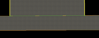
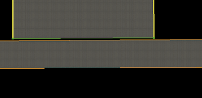
Here we have a 3-way junction, that is, one taxiway ending with another. First, what not to do:
First we have an overlapped solution. This is not good because overlap is wasteful of graphics card power. We also have the problem that the edge markings will overlap. So in the second and third picture, we “cut away” the horizontal taxiway markings by adding vertices. (In picture two we have overlap, in picture 3 we try to end the taxiway right at the intersection.)
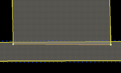
The problem with technique two is: we still have overlap (and imprecise markings). The problem with picure three is that we can’t guarantee that the vertices of the vertical taxiway are exactly “on top of” the horizontal taxiway edge. So you may get something in X-Plane that looks more like this:
(Gap exagerated for clarity.) This is a “slivering” problem. The solution is one that is both efficient and nice looking:
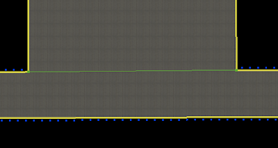
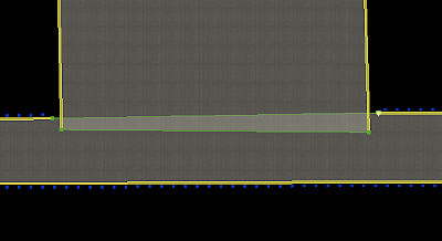
In this situation, I have inserted two vertices in the edge of the horizontal taxiway and then used “snap to vertex” to assure that the corners of the vertical taxiway are exactly the same as the “cut points” in the horizontal one. This gives me a connection that will look clean in x-plane with no cracks or slivering and no overlap. My lines also end at just the right places.
(Hint: once you do this, to move all of the overlapped vertices at once, select them all with the marquee tool and drag.)
Another issue I see sometimes with WED layouts is how to draw the “fillets”, or curved taxiways that touch runways. Because the lines are not as smooth in x-plane as WED, often users are surprised when the approximations of the bezier curves cause an overlap and theere is no pavement.
Note that we’re stuck – we can’t use the technique described above because we can’t insert vertices into the runway. So we have to overlap. Less overlap is better – the overlap here is exaggerated to make things clear.
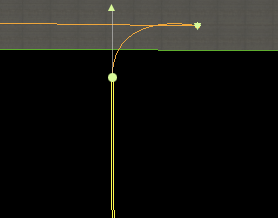
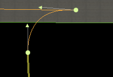
In this curve, we have a control handle only on the bottom vertex. It will overlap as soon as the control handle reaches the other side of the top line. By pulling the control handle down, we restore the curve.
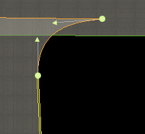
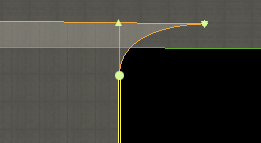
Here we have two control handles – now it is a question of whether the top control handle crosses the top of the taxiway.
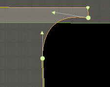
Here is one solution – at the expense of more overlap we can simply give ourselves some breathing room with our bezier curve. However, my preference would be to try to keep the control handles below the taxiway top by a wide margin.
I don’t actually know all of the best ways to make an apt.dat file. The format is new and we haven’t had a ton of time to performance test it. But here are some thoughts:
- One thing I know is…it is best to describe the shape you are using with the fewest number of nodes possible. In other words, let bezier curves do their thing, don’t add a ton of vertices to them. And please don’t add vertices to try to make the curves smoother. The best thing is to leave the layout simple and let X-Plane render it. In the future we will allow the user to set the level of smoothness based on his or her hardware. Adding more nodes will hurt quality – we will be able to pick better nodes at runtime than you can in the apt.dat file.
- Avoid overlapping large areas of pavement. Overlap is bad – it hurts framerate by requiring the graphics card to draw the same pixels over and over. As X-Plane supports more advanced shaders for nicer lighting, this cost will be a lot heavier on users.
- Ignoring overlap, the question of whether to have several smaller chunks of pavement vs. one large one is a difficult question. I would suggest moderation – try not to make too many individual pavement elements, but don’t make the entire element one giant pavement either. You may have to experiment to find the best framerate.
I posted previously in my blog that we use airport boundaries to flatten airports when we make the DSFs, as well as place airport grass. Let me clarify this a bit: there are two stages of flattening that we do.
- The flattening in the DSF is a “soft” flattening – we do not completely flatten the area, but rather we try to remove high frequency spikes in the elevation data, so that the airport maintains its overall shape without being unusable. This flattening process is very precise in that it only happens inside the airport area. Because we decide the mesh when making the DSF, we can shape the mesh to flatten only the airport area.
- If flattening in the sim is enabled, we then do a “hard” flatten of an area including the airport and some surrounding area. This flatten is truly flat and destroys any topography for the airport and a lot of surrounding terrain. Because the mesh is already defined, X-Plane is limited in its choices of where it can choose to flatten or not flatten.
Now that first soft flattening is what we use the airport boundary for. In X-Plane 800 the US DSF flattening worked very poorly. For the 820 flattening it worked well for most cases, but had some very specific bugs. (Typically the confluence of water, airport, and/or a DSF tile in close proximity would cause the three different processors for water, airport, and boundaries to come into conflict.)
I am going to try to further improve the flattening algorithm for the v9 render, with the hope of fixing some of the buggy cases from the 820 render. I am sure there will still be some broken cases – with 14,000+ DSF tiles, one of them is bound to be weird…but my hope is that with each re-render we can get closer to a render where users can run with sloped runways enabled and enjoy realistic non-flat runways.


