In MeshTool 2.0, you can specify how wet orthophotos are handled. There are three possibilities:
- The orthophoto has no alpha-based water. The alpha channel will be ignored.
- The orthophoto has alpha-based water. Draw water under the alpha, but for physics, make the triangles act “solid”.
- The orthophoto has alpha-based water. Draw water under teh alpha, and for physics make the triangles act “wet”.
The reason for 2 and 3 is that the X-Plane physics engine doesn’t look at your alpha channel – wet/dry polygons are decided on a per triangle basis. (The typical work-around is to use the “mask” feature in MeshTool to make some parts of the orthophoto be physics-wet and some physics-solid. This is described in the MeshTool README.)
Whenever possible: don’t use alpha-based water at all. It is certainly easy to set all of your orthophotos to alpha-water + physics-solid, but there are three costs to this:
- You eat a lot of fill rate. X-Plane manages alpha=water by drawing the water underneath the entire orthophoto, then painting over it with the orthophoto. This is fill-rate expensive. If you know there is no alpha, tell MeshTool, so it can avoid creating that “under-layer” of water.
- If the terrain is very mountainous, you may get Z-buffer artifacts from the layering, particularly for thin, spikey mountains (which probably aren’t wet anyway).
- The reflection engine tries to figure out the “surface level” of the water, but it doesn’t understand the alpha channel on top of the water. So all of that water “under” your mountain or hill is going to throw the reflection engine into hysterics.
Limiting the use of water under your orthophotos fixes all three problems.
It’s been a tough year for X-Plane authors. Key framing, manipulators, global lighting, baked lighting control, generic instruments, normal maps…version 9 has extended the possibilities for airplanes in a huge way. This is great for X-Plane users, and great for any author who wants to push the envelope, but there is a flip side: the time investment to make a “cutting edge” X-Plane aircraft has gone way, way up.
Here’s the problem: as hardware has been getting faster, the amount of data (in the form of detailed airplane models) needed to keep the hardware running at max has gone up. But the process of modeling an airplane hasn’t gotten any more efficient; all of that 3-d detail simply needs to be drawn, UV mapped and textured. Simply put, NVidia and ATI are making faster GPUs but not faster humans.
That’s why I was so excited about order independent transparency. This is a case where new graphics hardware and nicer looking hardware means less authoring work, not more. (The misery of trying to carefully manage ordered one sided geometry will simply be replaced by enabling the effect.)
My Daddy Can Beat Up Your Daddy
Cameron was on FSBreak last week last week discussing the new CRJ…the discussion touched on a question that gets kicked around the forums a lot these days: which allows authors to more realistically simulate a particular airplane…X-Plane 9 or FSX.
This debate is, to be blunt, completely moot. Both FS X and X-Plane contain powerful enough add-on systems that an author can do pretty much anything desired, including replacing the entire host simulation engine. At that point, the question is not “which can do more” because both can do more than any group of humans will ever produce. As Cameron observed, we’ve reached a point where the simulator doesn’t hold the author back, at least when it comes to systems modeling.
(It might be reasonable to ask: which simulator makes it easier to simulate a given aircraft, but given the tendency to replace the simulator’s built-in systems on both platforms, it appears the state of the art has gone significantly past built-in sim capabilities.)
Graphic Leverage
When it comes to systems modeling, the ability to put custom code into X-Plane or FS X allows authors to go significantly beyond the scope of the original sim. When it comes to graphics, however, authors on both platforms are constrained to what the sim’s native rendering engine can actually draw.
So if there’s a challenge to flight simulation next year, I think it is this: for next-generation flight simulators to act as amplifiers for the art content that humans build, rather than as engines that consume it as fuel. The simulator features that get our attention next year can’t just be the ability for an author to create something very nice (we’re already there), rather it needs to be the ability to make what authors make look even better.
(This doesn’t mean that I think that the platforms for building third party “stuff” are complete. Rather, I think it means that we have to carefully consider the amount of input labor it takes to get an output effect.)
I find it very difficult to write good documentation for the X-Plane scenery system and tools. Not only am I not a technical writer by training and not particularly good at explaining what I am thinking in non-technical terms, but since I have been working on the scenery system for over five years, I don’t really have good perspective as to what is complex and what is straightforward.
For this reason, I try to keep my ears open any time an author cannot understand the documentation, cannot find the documentation, or in another way has a problem with the scenery website. These “first experiences” give an idea of the real utility of the docs. Writing a reference for people who know things is not very hard – writing an explanation for new authors is much harder.
One author who was converting from MSFS to X-Plane pointed out a problem with the documentation that I hadn’t realized before – but I think he’s on to something. He pointed out that the information you need to complete a single project is often spread out all over the place. You probably need to look at an overview document, a file format, and a tool manual, each of which describes about 1/3 of the problem. To make it worse, each document assumes you know what the other ones say!
Who would write such poor documentation? A programmer, that’s who. (In other words, em.) In computer programming, the following techniques are all considered good design and essential:
- Breaking a problem into smaller, sections.
- Limited cross-references between these sections as much as possible.
- Keeping the sections independent.
- Not duplicating information (code).
In other words, the docs I have written for the scenery tools are a mess because they are “well factored”, a good thing for a C++ and a really useless thing for humans.
This is definitely not the only problem with the documentation, which also suffers from a lack of clarity, is often incomplete, and could use a lot more pictures. I am a programmer, and I am paid to make X-Plane faster, better, etc. It can be very hard to find the time to work on documentation when the next feature needs to be done. And yet…without documentation, who can use these features?
Now that I’ve at least figured out that factorization is bad, for the short term I am going to try to write “non-factored” documentation. The first test of this will be MeshTool. I am doing a complete rewrite of the MeshTool readme. Like the ac3d readme, MeshTool needs a full large-scale manual of perhaps 10-20 pages, and the task needs to be approached recognizing that the manual is going to contain a huge amount of information.
When I work on the MeshTool manual I will try to approach it from a task perspective, with explanations of the underlying scenery system, rather than a reference perspective that assumes authors might know why the given techniques work. We’ll see if this creates a more usable manual.
First, Merry Christmas and seasons greetings to, well, pretty much everyone – it’s been great to hear from everyone over the last week. I had a chance to poke at the scenery tools and have posted two new beta builds:
- MeshTool 2 beta 4.
- WED 1.1 developer preview 2.
You can download them both here.
MeshTool 2 beta 4 should be the last MeshTool beta short of bug fixes – that is, I’ve taken feature requests during the MeshTool beta, but I think we have what we need. Future feature enhancement will go in a later version.
Besides some useful bug fixes, there are two new features in this beta:
- You can specify a specific land class terrain with a shapefile.
- You can control the physical properties of orthophotos (are they wet or dry) with a shapefile without cropping out the water. This is useful for authors who want to use translucent orthophotos to create tinted water effects like coral or shallow sandy bottoms.
The WED developer preview simply puts up more bug fixes. WED isn’t quite beta because of one nasty limitation: the code that exports UV-mapped bezier curves doesn’t handle polygons that cross DSF boundaries. This code is going to be very difficult to get right – the combination of bezier curves, polygon cutting, and UV maps is a bit of a witches brew. Since WED isn’t really complete without this, I’m not calling the build a beta.
Also a docs update: I have posted the WED and Ac3d manuals in PDF form directly on the website. The AC3D manual (and motivation to do this) are thanks to Peter, who converted the manual from readme-text to PDF. I was shocked to realize the ac3d README is almost 20 pages. Hopefully having the manual in PDF form will help people realize just how much documentation is crammed in there.
I have two fundamental “rants” about flight simulator scenery, and the way people discuss it, market it, compare it, and evaluate it. The rants basically go like this:
- Mesh resolution (that is, the spacing between elevation points in a mesh) is a crude way to measure the quality of a mesh. It is horribly inefficient to use 5m triangles to cover a flat plateau just because you need them for some cliffs.
- At some point, the data in a very high mesh becomes misleading. You have a 5m mesh. Great! Are you measuring a 5m change in elevation, or is that a parked car that has been included in the surface?
X-Plane uses an irregular mesh to efficiently use small triangles only where they are needed. I have some pictures on this here.
But it brings up the question: how good is a mesh? If you make a base mesh with MeshTool using a 10m input DEM (the largest DEM you can use right now), the smallest triangles might be 10m. But the quality of the mesh is really determined by the mesh’s “point budget” – that is, the number of points MeshTool was allowed to add to minimize error.
MeshTool beta 4 will finally provide authors with some tools to understand this: it will print out the “mesh statistics” – that is, a measure of the error between the original input DEM and the triangulation. Often the error* from using only 1/6th of the triangles from the original DEM might be as little as 1 meter.
I spent yesterday looking at the error metrics of the meshes MeshTool creates. I figured if I’m going to show everyone how much error their mesh has with a stats printout, I’d better make sure the stats aren’t terrible! After some debugging, I found a few things:
-
Vector features induce a lot of “error” from a metrics standpoint. Basically when you induce vector features, you limit MeshTool’s ability to put vertices where the need to be to reduce meshing error. The mesh is still quite good even with vectors, but if you could see where the error is coming from, the vast majority will be at vector edges.
For example, in San Diego the vector water is sometimes not quite in the flat part of the DEM, and the result is an artificial flattening of a water triangle that overlaps a few posts of land. If that land is fairly steep (e.g. it gains 10+ meters of elevation right off the coast) we’ll pick up a case where our “worst” mesh error is 10+ meters. The standard deviation will be
-
The whole question of how we measure error must be examined. My normal metric is “vertical” error – for a given point, how much is the elevation different. But we can also look at “distance” error: for a given point, how close is the nearest mesh point from the ideal DEM?
“Distance” mesh point gives us lower error statistics. The reason is because when we have a steep cliff, a very slight lateral offset of a triangle results in a huge vertical error, since moving 1m to the right might drop us 20 meters down. But…do we care about this error? If the effective result is the same cliff, offset laterally by 1m, it’s probably more reasonable to say we have “1m lateral error” than to say we have “20m vertical error”. In other words, small lateral errors become huge vertical errors around cliffs.
Absolute distance metrics take care of that by simply measuring the two cliff surfaces against each other at the actual orientation of the cliff. That is, cliff walls are measured laterally and the cliff floor is measured vertically. I think it’s a more reasonable way to measure error. One possible exception: for a landing area, we really want to know the vertical error, because we want the plane to touch pavement at just the right time. But since airplane landing areas tend to be flat, distance measurement becomes a vertical measurement anyway.
Unnatural Terrain
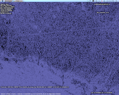
So there I am working with a void-filled SRTM DEM for KSBD. I have cranked the mesh to 500,000 points to measure the error (which is very low, btw…worst error 3m and standard deviation less than 15 cm.
But what are those horziontal lines of high density mesh?
I wasn’t sure what those were, but they looked way too flat and regular. So I look at the original DEM and I saw this:
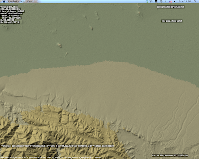
Ah – there are ridges in the actual DEM. Well that’s weird. What the heck could that be?
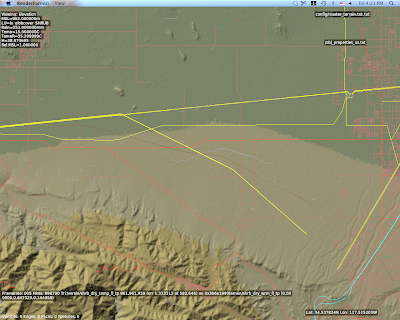
This is a view with vector data – and there you go. Those are power lines.
The problem in particular is that SRTM data is “first return” – that is, it is a measurement of the first thing the radar bounces off of from space. Thus SRTM includes trees, some large buildings, sky scrapers, and all sorts of other gunk we might not want. A mesh in a flight simulator usually represents “the ground”, but using first return data means that our ground is going to have a bump any time there is something fairly large on that ground. The higher the mesh res, and the lower the mesh error, the more of this real world 3-d coverage gets burned into the mesh.
So Do We Really Care About 5m DEMs?
The answer is actually yes, yes we do, but maybe not for the most obvious reasons.
The problem with raster DEMs (that is, an elevation as a 2-d grid of heights) is that it doesn’t handle cliffs very well. A raster DEM cannot, by its very format, handle a truly vertical cliff. In fact, the maximum slope it can create is based on
arctan(cliff height / DEM spacing)
Which is math to say: the tighter your DEM spacing, the higher the maximum slope we can represent for a given cliff at a certain height. Note that the total cliff height matters too, so even a crude 90m DEM like SRTM can represent a canyon if it’s really huge**, but we need a very high res DEM to get shorter vertical surfaces.
So the moderated version of my rant goes something like this:
- High res DEMs input DEMs are necessary to represent small terrain features that are steep if we are using raster DEMs.
- High res meshes are not necessary – we only need res for part of the mesh where it counts.
- Let’s not use mesh res to represent 3-d on the ground, only the ground itself.
There is another way to deal with elevation besides DEMs, and in fact it is used for LIDAR data (where the resolution is so high that a raster DEM would be unusable): you can represent a as a series of vector contour lines in 3-d. The beauty of contour lines is that they represent cliffs no matter how steep (up to vertical), and you don’t need a lot of storage if the ground is not very intricate.
The meshing data format inside MeshTool could probably be made t
o work with contours, but I haven’t seen anyone with high quality contour data yet. We’ll probably support such a feature some day.
* Really this should be “the additional error”, because when you get a DEM, it already has error – that is, the technique for creating the DEM will have some error vs. the real world. For example, if I remember right (and I probably do not) 90% of SRTM data points fall within 8m vertically of the real world values. So add MeshTool and you might be increasing the error from 8m to 9-10m, that is, a 12-25% increase in error.
** For the SRTM this might be a moot point – the SRTM has a maximum cliff slope in certain directions defined by the relationship between the shuttle’s orbit and the latitude of the area being scanned. The maximum cliff at any point in the SRTM is 70 degrees, which can be represented by a 247 m cliff using a pair of 90m posts.
The X-Plane version 8/9 default scenery uses raster land use data (that is, a low-res grid that categorizes the overall usage of a square area of land) as part of its input in generating the global scenery. When you use MeshTool, this raster data comes in the .xes file that you must download. So…why can’t you change it?
The short answer is: you could change it, but the results would be so unsatisfying that it’s probably not worth adding the feature.
The global scenery is using GLCC land use data – it’s a 1 km data set with about 100 types of land class based on the OGE2 spec.
Now here’s the thing: the data sucks.
That’s a little harsh, and I am sure the researchers tried hard to create the data set. But using the data set directly in a flight simulator is immensely problematic:
- With 1 km spatial resolution (and some alignment error) the data is not particularly precise in where it puts features.
- The categorizations are inaccurate. The data is derived from thermal imagery, and it is easily fooled by mixed-use land. For example, mixing suburban houses into trees will result in a new forest categorization, because of the heat from the houses.
- The data can produce crazy results: cities on top of mountains, water running up steep slopes, etc.
That’s where Sergio and I come in. During the development of the v8 and v9 global scenery, Sergio created a rule set and I created processing algorithms – combined together, this system picks a terrain type from several factors: climate, land use, but also slope, elevation, etc.
To give a trivial example, the placement of rock cliffs is based on the steepness of terrain, and overrides land use. So if we have a city on an 80 degree incline, our rule set says “you can’t have a city that slanted – put a rock face there instead.”
Sergio made something on the order of 1800 rules. (No one said he isn’t thorough!!) And when we were done, we realized that we barely use landuse.
In developing the rule set, Sergio looked for the parameters that would best predict the real look of the terrain. And what he found was that climate and slope are much better predictors of land use than the actual land use data. If you didn’t realize that we were ignoring the input data, well, that speaks to the quality of his rule set.
No One Is Listening
Now back to MeshTool. MeshTool uses the rule set Sergio developed to pick terrain when you have an area tagged as terrain_Natural. If you were to change the land use data, 80% of your land would ignore your markings because the ruleset is based on many other factors besides landuse. Simply put, no one would be listening.
(We could try some experiments with customizing the land use data..there is a very small number of land uses that are keyed into the rule set. My guess is that this would be a very indirect and thus frustrating way to work, e.g. “I said city goes here, why is it not there?”)
The Future
I am working with alpilotx – he is producing a next-gen land-use data set, and it’s an entirely different world from the raw GLCC that Sergio and I had a few years ago. Alpilotx’s data set is high res, extremely accurate, and carefully combined and processed from several modern, high quality sources.
This of course means the rules have to change, and that’s the challenge we are looking at now – how much do we trust the new landuse vs. some of the other indicators that proved to be reliable.
Someday MeshTool may use this new landuse data and a new ruleset that follows it. At that point it could make sense to allow MeshTool to accept raster landuse data replacements. But for now I think it would be an exercise in frustration.
On this week’s FSBreak, Holger Sandmann described MSFS’s scenery system as a “pie” made of layers. This made me think: well, in that case X-Plane must be a cake. It turns out X-Plane has been a cake for a while.
If this discussion seems tasty but confusing, let me clarify. The issue is: which parts of a scenery system are combined when the simulator runs, and which parts must be combined (“baked”) in advance.
With MSFS, you can separately install a new mesh, new land class data, new coastlines, and new orthophotos. In X-Plane, all four of those elements must be pre-combined into a single “base mesh”. In X-Plane, you have to bake those elements.
This means that you can’t make “just” an add-on mesh for X-Plane. You have to create an add-on that addresses elevation and land class and orthophotos and water. Third party authors are quite often not very happy about this – I don’t know how many times I’ve seen “can I replace just the elevation and not the water” posted in forums.
But the Orbx team brings up the exact reason why I thought (five years ago when designing DSF) that requiring all of the elements would be okay: often if you replace one part of the scenery and not another, the results are inconsistent. If you move a coastline but don’t adjust the mesh, you may have water climbing up a mountain. If you move a mountain but don’t adjust the landuse, you may have a farm at a 45 degree angle.
Cake and Pie
Not everything in X-Plane is pre-baked. As of X-Plane 940, you must pre-bake:
- Land class
- Wide-scale orthophotos
- Terrain Mesh
- Coastlines
You can separately replace:
- All art assets (E.g. change or add types of buildings, replace the look of a given land class for an area).
- All 3-d (forests, buildings, airports, roads*).
- Small area orthophotos
Orthophotos are on the list twice. This is because X-Plane has two orthophoto technologies. Draped polygons (.pol files) can be overlaid anywhere, but they degrade performance if used over too large of an area. They are really meant for airport surface areas and other “detail” work. Orthophotos terrain (.ter files) can be used over huge areas with no performance problem, but must be baked.
* Roads are sort of a special case in X-Plane 9: you can replace them with an overlay, but the replacement roads must be “shaped” to the underlying terrain mesh, which means they won’t work well if a custom mesh is installed. This limitation in the road code dates back to X-Plane 8, when most of us had only one CPU – pre-conforming the road mesh to the terrain shape saved load time.
I had a conversation with a third party developer the other day – he offered to sign a non-disclosure-agreement (NDA) and wanted to know: would custom scenery he made for X-Plane now keep working with the next major version?
Well, no NDA is necessary for that. The simple answer is: yes! (A more complete answer is: if you use the current file formats and not legacy formats from 9 years ago, then yes.) Here’s a quick review of how long the various scenery and modeling file formats have been supported:
- DSF: 5 years
- OBJ8: 5 years
- OBJ7: 7 years
- ENV: 9 years
- OBJ2: 9 years
With X-Plane 8 we rewrote a lot of the rendering engine – since then, rendering engine enhancements have been incremental, building on what we have. The next major version will be like that too: the new version will do more than X-Plane 9, but it’s not going to drop existing capabilities.
So if you model a building with an OBJ or model a terrain area with a DSF, I expect that it will work unmodified with the next major version.
Modeling Formats in Detail
X-Plane 9 supports 3 revisions of the OBJ file format (X-Plane’s modeling format):
- Version 800, which is the current version. Introduced with version 8, the OBJ800 format has been extended heavily, but the format was never changed, so original version 800 objects are not incompatible.
- Version 700, which was used with version 7.
- Version 2, whic hwas used for most of the X-Plane 6 run.
The next major version will clearly support version 800, and will probably support version 700 as well.
Do not make new objects in the version 700 format! This format is obsolete, supported only for legacy purposes, and is an inferior format.
We may drop support for version 2 objects – I haven’t seen user content with a version 2 object in a very long time. Version 2 objects date back to a time when every polygon was expensive, so content authored in version 2 is likely to look, well, ten years old.
If you do have version 2 content, you can use ObjConverter to convert it to version 800 format. (ObjConverter will also convert version 700 OBJs to version 800.)
Scenery Formats
DSF has been our scenery format for five years now, and will continue to be so. DSF has not had any format revisions – new features are supported by allowing DSF data to be tied to new art asset formats.
I do not know if we will support ENV in the next major version. Supporting ENV is relatively trivial in the code, but whenever there is a bug, we have to fix it in the legacy ENV code as well. ENV supports a 500m terrain mesh, which is completely obsolete by today’s standard.
Do not make new content in the ENV format! Like OBJ 2 and 700, it is a legacy format for backward compatibility.
Tom had a good question that others have asked me too: why not ignore missing scenery resources? Why does X-Plane act so cranky?
Ignorance Is Bliss
We have tried the other approach: ignore missing art assets. ENV based scenery in version 7 did not require custom objects to actually be available – missing objects were ignored.
When I was working on the ENV reader for version 8 (the ENV code needed to be retrofit into the new rendering engine) I found to my surprise that virtually every ENV-based custom scenery pack I looked at was missing at least a few of the OBJs that the ENV referenced! I don’t know how this happened – it seems that in the process of working on scenery, authors started to “lose” objects and simply never noticed.
Quality Control
When we developed DSF we had a chance at a clean slate: there were no DSFs in existence so we could set the rules for art assets any way we wanted. So we picked the harshest rule possible: any missing art asset was illegal and would cause X-Plane to refuse to load the scenery package, with no way to ignore the error. Why be this rude?
- Missing artwork failures are 100% reproducible – you don’t have to try your package more than once to see the problem. If you are missing an art asset, you will have the failure every single time you run.
- The error is found on load – you don’t have to fly over the art asset to discover that it is missing.
- Therefore if an author tests a scenery package even once, even in the most trivial way, he or she will discover the missing art asset.
- Once the error is fixed, it is fixed forever, so a scenery pack that passes this quality control measure in development will be just fine “in the wild”.
- This rule has been in place since 8.0 beta 1 for DSFs, so there are no legacy DSF files that would have this problem.
Libraries
There is one special case worth mentioning: a scenery pack might reference an art asset in another scenery pack, and that other scenery pack might not be installed. This is why the library file format allows for “export_backup”. (Read more here and here.) Export_backup is your scenery pack’s way of sayingg “only use this art asset if you can’t find it somewhere else. It lets you provide emergency art-work in the event the other library is not installed.
What should you use as an emergency backup art asset? It could be anything – a big floating question mark, an empty object, a poor approximation of the desired art asset. But my main point is that responsibility for location of art assets lies with the author of a pack – so if you make a scenery pack, be sure to provide backups for any libraries you use.
(If you use OpenSceneryX, the library comes with a “developer pack” – read more here. Basically they already built a “backup” library that you can put in your scenery pack to avoid nasty messages from X-plane when OSX isn’t installed.)
Order independent transparency (OIT): first, the shiny robot.
So first, what’s so special about this? Well, if you’ve ever worked with a lot of translucency in X-Plane, you know that it doesn’t work very well – you invariably get some surfaces that disappear at some camera angles.
The problem is that current GL rendering requires translucent surfaces to be drawn from farthest to nearest, and who is far and who is near changes as the camera changes. There are lots of tricks for trying to get the draw order mostly right, but in the end it’s somewhere between a huge pain in the ass and impossible.
What’s cool about the robot data is that the graphics card is drawing the transparency even if it is not drawn from back to front, which means the app can just shovel piles of translucent triangles into the card and let the hardware sort it out (literally).
X-Plane is currently riddled with transparency-order bugs, and the only thing we can do is burn a pile of CPU and add a ton of complexity to solve some of them partly. That proposition doesn’t make me happy.
So I am keeping an eye on hardware-accelerated OIT – it’s a case where a GPU feature would make it easier for modelers to create great looking content.


