> 💡 NOTE: X-Plane’s Taxi-Sign Specification was originally a joint effort between FlightGear and X-Plane and applicable to both simulators; however, X-Plane has evolved in a differing direction and this specification may no longer be applicable to Flight Gear.
General
3D Taxi-Signs in X-Plane are auto-generated, and the glyphs (letters and symbols) on each Taxi-Sign are rendered from a text string of ASCII characters called a taxi sign stringorsign string. S_ign strings_ for each Taxi-sign are part of the apt.dat file.
Sign strings are case sensitive! When we write “A-Z”, we mean upper case letters. When we write “a-z”, we mean lower case letters.
Sign strings may contain NO new line characters and NO whitespace characters (tab, spaces)
Example Taxi Sign String: {@L}P2{@R}16-34CAT{r1}{@Y}{@@}{^lu}P2{@L}P2
Glyphs
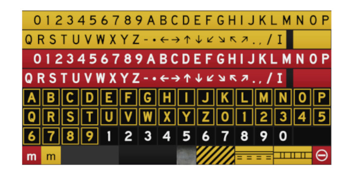
A glyph is simply a graphic shape that means something. The letters of an alphabet are glyphs. Symbols are glyphs. Egyptian hieroglyphics are glyphs, etc. We use the term glyphs here because a Taxi-Sign contains more than just letters in an alphabet. The image below shows all the possible Taxi-sign glyphs that are available in X-Plane.
A Taxi-Sign glyph is represented / encoded by either a single ASCII character (single-char-glyph) or a ASCII character sequence (multi-char-glyph). We call these encodings glyph-strings; therefore, a Taxi-sign’s contents are rendered from a taxi sign string, which further consists of individual glyph-strings.
Curly Bracket Pairs
Curly brackets are used to bracket either Control Directives, or multi-char-glyphs. The following rules apply to the use of curly braces
Every open curly brace must have a closing curly brace.
Curly brace pairs must not be empty.
Nested curly braces are not supported.
Control Directives:
Control directives are two-character sequences in brackets that tell X-Plane which color category of Glyph to use, as well as delimit what is on the front and back of the sign. Control directives for the color category are modal, meaning all glyphs after that directive will use that color until another color directive is specified. There are five directives available as follows:
Directive
Description
Glyphs Supported
@Y
Use Yellow background set
Supports all valid glyphs
@R
Use Red background set
Supports all valid glyphs
@L
Use Black background with yellow chars
Supports only A-Z, 0-9
@B
Use Black background with white numbers
Supports only 0-9
@@
following glyph strings for back of sign
Single Char Glyphs
Single char glyphs are represented by a single ASCII character, for example A, –, 6, etc. The following are valid single letter glyphs:
Character
Description
A-Z
Capital Letters A thru Z
0-9
Integers 0 thru 9
-
produces a hyphen
*
produces a dot
.
produces a period
,
produces a comma (when used outside brackets
/
produces a slash separator
_
produces a space
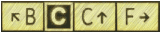
Multi Char Glyphs
Multi char glyphs are glyphs that are encoded using more than one ASCII character. Multi char glyphs must be contained inside curly brackets unless the Taxi Sign String qualifies for Comma Delimited Syntax. The image below highlights the glyphs that use multi char glyph strings.
The following table lists the multi-char glyph strings:
Glyph String
Description
^u
Up Arrow
^d
Down Arrow
^l
Left Arrow
^r
Right Arrow
^lu
Left Up Arrow
^ru
Right Up Arrow
^ld
Left Down Arrow
^rd
Right Down Arrow
r1
Roman Numeral I
r2
Roman Numeral II
r3
Roman Numeral III
no-entry
“Do not enter” symbol
critical
ILS Critical Area Boundary sign
safety
Runway Safety Area
hazard
Taxiway Ending Marker
comma
For an actual comma on the sign
> 💡 NOTE: The character, ^ is only valid when used with the multi-char glyph strings above.
Fixed Glyphs
Fixed Glyphs are those glyphs that always appear the same, regardless of the active color directive. The following are the fixed color glyphs: hazard, safety, critical, no-entry
Divider Line
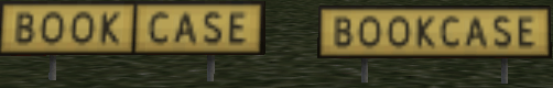
The Divider Line is a special glyph, encoded by the pipe symbol, ‘|’, and having some special rules for its use. Below is an example of two signs, one with and one without the Divider line. The Taxi Sign String used to produce each sign contents is also given.
{@Y}BOOK|CASE{@Y}BOOKCASE
The following conditions apply to use the Divider Line / pipe symbol
A Divider Line must have the same color glyphs on either side of it.
e.g. {@Y}BOOK|{@R}CASE is illegal.
The Divider Line only works for @Y, @R, and @L color modes. Any pipe symbol following a @B directive is ignored.
A divider line cannot be:
next to a Fixed Glyph
next to another Separator Line
at the beginning or end of a sign side.
Comma Delimited Syntax
When a Taxi Sign String only contains a single directive, then the Taxi Sign String may be fully contained within a single set of curly brackets along with the one Control Directive; however, each glyph string after the directive must be comma delimited. This reduces the amount of curly brackets required for single sided signs with only one color mode, e.g.
{@Y,^lu,TERMINAL,|,CARGO,^ru}
Unsupported Characters
!
“
#
$
%
&
‘
(
)
[
]
+
:
;
<
=
>
?
~
b
g
j
k
q
v
w
x
Example Taxi Sign Strings
{@L}A
{@Y}{^l}C
{@Y}17-35{^r} or {@Y,17-35, ^r}
{@B}1 or {@B,1}
{@R}11-29 or {@R,11-29}
{@L}B7{@R}10CAT{r2}/{r3}
{@Y}{^lu}B{@L}C{@Y}C{^u}|F{^r}
{@Y}WEST_APRON{^r} or {@Y,WEST_APRON,^r}
{@L}P2{@R}16-34CAT{r1}{@Y}``{@@}{^lu}P2{@L}P2 (Front Side – blue text)
{@L}P2{@R}16-34CAT{r1}{@Y}{@@}``{^lu}P2{@L}P2 (Rear Side – blue text)
> 💡 The following table is a table of Control Directives that are only used for error reporting and internal usage. They cannot be used by hand.
@I
Glyph specific
These are the Fixed Glyph Signs: critical, no-entry,safety, and hazard and cannot be declared by hand
@P
Represents a pipebar, only for error reporting
Indicates the glyph is a pipe bar and should be checked if valid
@X
Only for error reporting
Indicates that parsing stopped before any valid color has been found
The Gateway provides a method for airport scenery artists to submit new or updated airport sceneries for inclusion into future releases of X-Plane. Submissions are made (by artists from the community) to the Gateway directly from the Laminar Research airport-building tool “World Editor” (WED). Submissions must comprise only Laminar Research scenery library assets.
Laminar Research thanks all artists for contributing their work to the Airport Scenery Gateway.
Airport submissions are captured by Laminar Research periodically from the Gateway, for inclusion into a future release of X-Plane. Airport submissions that have a status of “Recommended” (by the moderator) at the moment of capture will appear in X-Plane.
The ‘Wanted Airports’ button is a great place to start – this feature provides a list of airports that are missing scenery or have old scenery that needs updating.
If you already have an airport in mind, you may search for it by identifier or name. If this airport is found on the Gateway, select it in the grid.
If the airport does not yet exist on the Gateway, you will need to log in and file a New Airport Code Request
Airport Locking
To avoid two or more artists working on the same airport, the Gateway has a ‘lock’ feature. When an airport is ‘locked’, this informs the community that someone is working on it.
Checking the lock-status of an airport
Log in to the Gateway and search for your airport using the identifier or name. If this airport is found on the Gateway, select it in the grid. The lock-status of the airport is shown above the submission history tree. If the airport is currently ‘locked’, the name of the artist and the lock-expiration date are shown.
Locking an airport
If the airport is available, and you are ready to begin developing it, click the ‘Lock this airport to work on it’ button. Be sure to do this only if you are serious about starting work on the project immediately.
Un-locking an airport
You may release your lock on any airport by clicking the ‘Release Lock’ button. Do this ONLY if you are sure there is no further development work to be done. Once you release an airport, you will not be able to lock it again until a grace-period has elapsed.
Importing an airport from the Gateway into WED
On the Gateway – navigate to the page of the airport you intend to work with and check its submissions-history. If one or more submissions exists for this airport already, you will need to import the Recommended submission into WED as your starting point. If no submissions exist already, you may skip this step.
Start WED and create a new airport project.
Open the new airport project.
Select File | Import From Airport Scenery Gateway
Wait for the list of airports to be populated.
Input the airport identifier or name into the edit box above the list, and then select the airport in the results that are returned.
Click ‘Next’.
Select the ‘Recommended’ submission.
Click ‘Import Packs’.
Exporting an airport from WED to the Gateway
Select the airport you want to upload in the hierarchy pane (you may only upload one airport at a time).
Set the “Target X-Plane Version” in the File menu to “Airport Scenery Gateway.”
Select File | Validate to check your airport for errors. Validation errors will need corrected for the upload feature to become enabled.
Select File | Export to Airport Scenery Gateway.
Input your username, password, and any comments about this work that you wish the moderator and community to see.
Click “Upload.”
Tracking your airport’s progress on the Gateway
Check back periodically to follow the progress of your airport submission on the Gateway. Airports may have the following status:
Uploaded (Not yet acknowledged by the moderator.)
Accepted (This airport submission has been acknowledged by the moderator, but not yet evaluated.)
Approved (This airport submission has been approved as suitable for inclusion in a future release of X-Plane. “Approved” submissions may be downloaded from the Gateway by X-Plane users. However, if there are multiple approved submissions for the same airport, only the “Recommended” submission is a candidate to appear in a future release of X-Plane.)
Recommended (Denoted with a star in the adjacent column – this airport submission has been recommended for inclusion in a future release of X-Plane. Airport submissions that are “Recommended” at the moment of capture will appear in the next release of X-Plane.)
See Comments (This airport submission could not be approved by the moderator. The reason for this can be viewed by clicking the moderator comment that applies to this submission.)
If you encounter any bugs or unexpected issues with WED, the Gateway site, or an airport submission, please report them using the bug reporter on the Gateway site.
Decals are overlay textures that sit on top of a regular albedo (day-time) texture to add high-frequency, high-res detail to an existing texture.
A typical use of decals might be:
To add a grassy leafy pattern to a field or airport grass texture.
To add a gravel pattern to a runway or road.
Decals work by modulating the textures they overlay. Decals typically repeat much faster than the base texture, but may also be used at a very low frequency to add subtle changes in the overall brightness of the terrain across a very large area, helping to disguise repetition.
Decals contain high frequency pixels at high res; when viewed from far away, the entire decal blends together into a constant color/grayscale. The decal shader ensures that when a decal has become a solid tone (because it is far away) the net result is the same as your underlying albedo. In other words, as you move away from the decal, the decal blurs into “no effect”. This means that you can generally apply decals and not worry about the effect on the far-away view.
Decal Texture Formats
A texture typically has two decals together:
One RGB decal in the color components of the texture.
One alpha decal in the alpha channel.
If you do not need the RGB decal, you can save VRAM by having a decal with only alpha (this is done using a gray-scale no alpha png on disk). If you need the RGB decal but not the alpha decal, there is no VRAM savings (the alpha channel is included in VRAM no matter what) so you might as well use the alpha channel for something.
Decal Application
Decals are applied by specifying a DECAL command in the text file for the art asset. (Decals are allowed in any file that uses the Standard Shader, including .ter, .pol, and .net files.) The DECAL command specifies the texture to use and the mixing parameters that control application.
Examples
The following examples are based on some of Albert’s and Sergio’s terrain textures, and attempt to show some of the possible ways decals might be applied. They are not intended to be perfect, and make use of decal textures that Alex happened to have lying around! The examples also include some suggestions for normal map usage. For the purpose of these examples, the terrain files were applied to flat, horizontal mesh – mainly for convenience!
Example 1
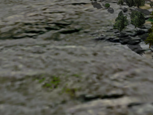
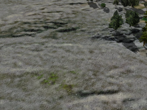
The first example is based on Albert’s rock_cld_hill_d.png albedo (as far as we’re concerned, “albedo” is just another name for “daylight texture”).
Here is a small section of it, in it’s basic form:
First, we will use the DECAL command to apply a grayscale detail texture. DECAL is the simplest form of X-Plane decal, and has the following characteristics:
It can only every apply a greyscale decal texture. X-Plane greyscale decals are applied using a blending mode similar to Photoshop’s “hard light” mode.
The decal is applied evenly across the entire area of the albedo.
DECAL has just two parameters: a scale ratio, and the texture file name.
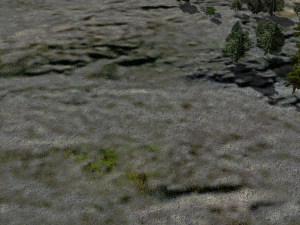
DECAL 25.0 ..textures/soil/DECAL_stony_dirt.png
Adding this line to the file means that we will apply DECAL_stony_dirt.png at 25.0 x the frequency of the albedo, in other words, it will repeat every 60 metres. (Note: the decal texture does NOT need to have the prefix DECAL – I just happen to use that convention).
This is the result:
In some cases, a simple, homogenous greyscale decal like this will be enough. In our example, however, the albedo contains patches of vegetation. It would be nice to apply a different decal to the vegetation, instead of DECAL_stony_dirt.png. To do this we can use either DECAL_KEYED or DECAL_PARAMS, the other two types of X-Plane decal. There are two ideas we need to understand first:
Although we will be using two separate decal images, they will both be squeezed into a single texture file! By using a combination of one RGB decal and one greyscale decal, we can save VRAM by putting them both into a single RGBA file. The greyscale image goes into the alpha channel. This means, of course, that only one of our two decals will be in colour, but in practice, there are many cases where greyscale can be very effective. Both DECAL_KEYED and DECAL_PARAMS reference only a single texture file, therefore, even though they let us use two decal images. There is a restriction, however: both images are applied at the same scale. In other words, they will both cover exactly the same area of terrain.
We control exactly which decal gets applied to which areas of the albedo by using a key. A key is a variable which tells the shader how strongly to apply a decal to a given pixel of the albedo texture. DECAL_KEYED uses a single key to control both the RGB and the greyscale decals, while DECAL_PARAMS uses two keys, one for each decal. Each key has four controls: R, G, B, and A. By tuning these controls, we can apply a decal more aggressively to some pixels than others.
Let’s continue with our example by removing the simple greyscale DECAL, and replacing it with a DECAL_PARAMS. We will be using an RGBA decal texture which contains an RGB “vegetation” decal, and a greyscale “stony_dirt” decal – in fact, the greyscale decal is exactly the same image as the one we used before, the only difference is that this time it lives in the alpha channel of an RGBA texture instead of being a discrete file of its own:
The first parameter is the scale ratio, relative to the albedo (BASE_TEX), exactly the same as it is in the DECAL command.
The second parameter is the “dither ratio”. It controls the relative influence of the albedo and the decal on composite border dithering.
The next four parameters are the controls for the RGB decal’s key.
The next four parameters are the controls for the greyscale decal’s key.
The last parameter is, of course, the decal texture file name.
How do the parameters get these values?
We set the scale ratio as before, at 25:1, so that the decals both repeat every 60 metres.
We set the dither ratio to 0.5. This means that the albedo and the decals will have roughly the same influence on the shape of the rendered borders. Higher values favour the decal. This means that if, like in this example, the decal is of higher frequency that the albedo, increasing the value of this parameter will make borders more “finely-grained”.
This is where it gets a bit more complicated!
Looking at the albedo texture, we observe that the rocky parts are mainly grey and relatively light in colour (ignoring baked shadows for now). On the other hand, the vegetation is mainly green and rather darker than the rock. (This statement is clearly an approximation, but is accurate enough for our purposes.)
Therefore, by tuning the RGB decal’s key to respond to darker, predominantly green colours, the areas of vegetation will receive more of our RGB decal, which is conveniently a sort of “shrubby” image.
In a similar fashion, by tuning the greyscale decal’s key to brighter, grey tones in the albedo. those areas will receive more of the greyscale decal – our “stony dirt” image from before.
The actual values for the two keys are usually found by experiment, and do not follow any particular rules or equations. Experimentation is probably the best way of getting a feel for the controls, but this is how I arrived at the values in our example:
The second key (the one controlling the greyscale decal) is a bit more obvious that the first one, so we’ll start with that. We want the rocky decal to be applied only to bright areas, so we set high values for R (=2.0), and B (=2.0). However, we don’t want it to respond to green (we don’t want rocks on our vegetation) so we set a low value for G (=-2.5). As mentioned at the top of this page, the exact function of control A depends on what other shader tricks we’re using in the .ter file. In this case, it is simply a constant value which gets added to the R, G and B values. Basically, the greater the value of A, the more of that decal we will get. So in the case of our greyscale decal key, we set A to zero, because we only want to see the decal on bright colours. If we were to set a higher value for A, we would see the decal regardless of the colour of the albedo!
Now let’s look at the first key, the one which controls our RGB “shrub” decal. In contrast to the greyscale decal, we want to see the RGB decal on both light and dark parts of the albedo – provided they are greenish. Therefore, we start by setting a high value for A. Doing this will draw shrubs over everything, so we must now tune out those areas we want to be shrub-free, by reducing the values of both R and B to -3.5.
The reason why some of these values are greater than 1.0 is that in order to get a reasonably sharp transition between regions of vegetation and regions of rock, we have to exaggerate the effect of the tuning controls. The actual difference in tone between a “veg” pixel and a “rock” pixel is generally pretty small, so we need to crank up the controls in order to get some “grip” on the albedo. The final key values are clamped between 0.0 and 1.0, so “overdriving” the key values will not cause artefacts in actual visible textures.
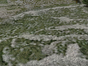
Here is the result:
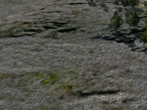
Here is the same decal applied to a different albedo (sparse_cld_steep_D.png) with exactly the same parameter values:
To return to our first example, let’s now try adding a normal map. First, we’ll use a normal map that was originally designed to suggest rough, open grassland. It was made by hand-painting a greyscale height-map in Photoshop, using a soft-edged pen to create hummocks and clumps of grass, and basic noise to add “grit”. This was then baked into a normal map in Blender. Although it is doesn’t match the albedo, it still adds a nice sense of richness and depth to the terrain, and by adjusting the scale, quite a satisfying effect can be achieved:
Changing the scale of the normal map (from 6.0 to 11.0) creates a slightly different effect:
General Observations Regarding Decals and Normal Maps in the context of terrain
The following points are based on the results of tests so far conducted by the author (Alex) and on some more general resource-management considerations.
Effective scaling
It seems that best results are obtained when the scale ratios between individual elements within a terrain definition is not “too large”. If the scale ratio between one element and the next-closest-in-scale exceeds a value in the region of 100 – 150, it is difficult to make them look integrated. Instead, they are likely to look like independent, unconnected layers, which is generally not desirable. An effective strategy for combining multiple elements in cases where the scale ratio between the largest and smallest is great seems to be one of adding an additional element of intermediate scale. For example, if a 10 x 10 m decal is applied directly to a 4000 x 4000 m albedo, the effect will probably not be good, since the scale ratio is very large: 400.0. However, adding a normal map of an intermediate size, say, 100 x 100 m, will help to bind the decal to the albedo, because the largest relative ratio between _successive_ elements is now 40.0:
Element       Size (m)      Scale Ratio     Relative Ratio
Albedo       4000 x 4000         -
Normal map    100 x 100         40.0             40.0
Decal          10 x 10         400.0             10.0
It is this relative ratio which appears to be critical to the effectiveness of the terrain. The exact order or type of the elements seems less critical. For example, an alternative strategy in the above case might be to use a 100 x 100 m decal and a 10 x 10 m normal map.
Realism versus Impressionism
In my earlier experiments, I took a literal, realistic approach to design, choice, and scaling of decals – I attempted to match their size and content as closely as possible to the real world. However, results seem to suggest that, in many cases, a looser, more impressionistic approach can be as – or more – effective.
For example, it is possible to use a “park grass” decal to suggest much rougher terrain simply by reducing its scale ratio (thus increasing the area it covers). Similarly, a normal map designed to suggest a field of boulders might be used at a smaller size to represent fine scree.
Arguably, a truly accurate effect is beyond the scope of our system, and would require a disproportionate allocation of resources to make it work. However, I’m of the opinion that by adopting a more impressionistic approach, really good results can nevertheless be achieved, without obvious compromise of realism. In the previous section’s Example 1, a greyscale decal representing loose, stony ground is applied to a sheer rock albedo. Even though it is not strictly speaking realistic, it nonetheless adds interest and richness to the terrain. That particular example is probably taking this principle a bit too far – a more appropriate decal would make for a more realistic effect – but in terms of our visual priorities, it is suggested as a potentially acceptable method by which to add detail to our terrain reasonably quickly.
Comments Off on Using Decals to Add Detail To Scenery
Painted line files (.lin) define taxiway markings that can be draped over DSFs, although they could can be used for other purposes too.
Painted line files are standard X-Plane 8 text files starting with a header and then commands. The # defines a comment.
A
850
LINE_PAINT
Painted lines are defining polygons in the DSF file. The polygon may have windings – only lat and lon coordinates are needed. The polygon parameter is used to indicate a closed loop (1) or open chain (0).
If two coordinates are provided (lon, lat) then the line is made of line segments. But if it is made of four coordinates (lon, lat, control lon, control lat) then it is interpretted as bezier curves.
The commands define the line:
TEXTURE <texture>
The texture command specifies the texture to be used for the painted lines. It is located relative to the .lin file. Night lighting is not available for painted lines.
SCALE <horizontal> <vertical>
The scale command defines how large the texture is in meters when applied. The parameters are in meters and represent the size of the entire texture.
TEX_WIDTH <pixels>
The horizontal coordinates are specified in terms of a texture of this width. In other words, this defines the scale in which horizontal coordinates are specified. So if your TEX_WIDTH is 1024, your middle pixel is 512, even if your whole texture size is only 16 pixels wide.
S_OFFSET <layer> <s1> <sm> <s2>
Each line is drawn in multiple layers, numbered consecutively starting at 0. Each line has three horizontal texture coordinates – a left, middle and right. The middle coordinate is aligned with the DSF line. The texture is simply repeated from top to bottom.
LAYER_GROUP <offset> <name>
[XP930:] This specifies which layer group (z order) to draw the polygon in. The definition is the same as the ATTR_layer_group command in the OBJ8 spec.
MIRROR
[XP930:] Normally a rounded or bent line is made by stretching the texture, forming trapezoids out of the lines. However when the mirror command is present in the file, X-Plane may reverse the texture direction to form clean cuts at sharp corners. This lowers the artifacts due to sharp corners in lines with lateral markings, but is in appropriate if the line has a clear longitudinal “direction” (e.g. a line with text in the texture along the long axis).
ALIGN <segments>
[XP1135:] Normally the texture for a .lin is repeated vertically over and over based on the vertical resolution parameters, and then it stops. To aid in alignment with end-caps, the ALIGN directive divides the line texture vertically into one or more segments. The line’s vertical texturing will then be stretched or shrunk to ensure that the line starts and ends on a segment boundary. If end-caps are used, they are subtracted out of the line before the stretching is done.
Note: ALIGN_SPLITS and MIRROR are incompatible – only one can be used at a time.
START_CAP <layer> <s1> <sm> <s2> <t1> <t2>
[XP1135:] This defines a start cap – a square of texture that will be used once before the line is drawn. Besides the horizontal positioning (left, middle and right), two vertical parameters (t1, t2) define the bottom and top of the cap. The start cap is applied to the “beginning” of the line, defined in a DSF as the first point in the polygon in DSF file order.
END_CAP <layer> <s1> <sm> <s2> <t1> <t2>
[XP1135:] This defines an end cap – a square of texture that will be used once before the line is drawn. Besides the horizontal positioning (left, middle and right), two vertical parameters (t1, t2) define the bottom and top of the cap. The end cap is applied to the “ending” of the line, defined in a DSF as the last point in the polygon in DSF file order.
Note: start and end caps are not used if the DSF file specifies a closed loop.
TEX_HEIGHT <pixels>
[XP1135:] This tells X-Plane the height of your texture in pixels. All “t” (vertical) coordinates int he file are interpreted in terms of this directive, not the actual texture height.
X-Plane uses a vector definition file (.net as in network) to visually render road networks. DSF files specify vectors by type and subtype. The type indicates what .net file to use for the roads; the subtype indicates a style of road within the .net definition file. The default scenery defines 62 vector types; you may replace the default road artwork by using the same subtypes, or use your own subtype numbers for your own custom scenery. Vector Network definition files are standard X-Plane text files with 3-line headers. Each command then takes one line, with parameters separated by spaces. A vector contains one or more subtypes and uses one or more textures. Each road subtype must use only one texture.
        A
        800
        ROADS
TEXTURE
This command specifies a texture to be used by the vectors. The bitmap should have the file extension on it. The numeric parameter indicates the amount of Z-buffer offseting to use when using this texture. A positive number helps X-Plane draw the vector on top of the terrain mesh without Z-buffer thrash. Zero indicates no offsetting; this setting is good for bridges. The texture command establishes an index number for that texture within the .net file. The first texture command will be texture 0, the second texture command 1, etc. Note: if you need to sometimes use a texture with z-buffer offsetting and sometimes without, simply include it twice with different Z-buffer offsets. This will establish two indices for the texture, but X-Plane will only load the texture into VRAM once.
TEXTURE <z offset> <filename>
TEXTURE_LIT
This command establishes a night-lit texture to go with the main texture for a road network. If this command is used at all, there must be one for each texture command, and they must follow in the same order. X-Plane will not automatically find _LIT bitmaps without this command.
TEXTURE_LIT <filename&ht;
SCALE
Normally texture coordinates are specified fractionally, e.g. 0.2 for a pixel 2/10ths of the way through the texture. The scale command indicates that all texture coordinates are multiplied by a fixed constant. If this command is not included, it is as if the scale is 1.0. The scale is applied to all commands that follow the scale command. Note: This allows you to work in terms of the pixel positions of the texture instead of fractional coordinates. But X-Plane does not take the real texture size into account. You can use a scale of 1024 even if the texture is not 1024×1024 pixels.
SCALE <scale>
ROAD_TYPE
This indicates information about a new road type. Segment, wire, and object commands apply to the previously declared road type. The road type takes seven parameters:
The numeric road subtype. This is an integer defining the road subtype. X-Plane matches this road type against the “subtype” field in the DSF file. (See the DSF spec for more info.) Road subtypes do not have to be consecutive or in ascending order in a road network file, but each road subtype should only be used once.
Segment width (meters). This defines how wide the vector is. All width-related info is relative to this defined width.
Repetition length (meters). This defines how many meters one length of the texture are applied to.
Texture index (zero based). This defines which texture to use, based on the texture commands previously defined.
Red fraction – a ratio from 0 to 1, indicating the percentage of red to use to draw this vector in the map view.
Green fraction – a ratio from 0 to 1, indicating the percentage of green to use to draw this vector in the map view.
Blue fraction – a ratio from 0 to 1, indicating the percentage of blue to use to draw this vector in the map view.
The segment command defines one quadrilateral section of a road. Segments are extruded along the length of a road vector. The simplest possible road would have one segment. Segments are defined in terms of their lateral extent, meaning how far across the road they go, and their vertical extent, meaning how far above and below the road they go. Lateral extent is defined as a ratio, where 0.0 is the left side and 1.0 is the right side. (Segments cannot extend outside the width of the segment – if you need ot make a wider segment, define the whole vector type to be wider using the ROAD_TYPE command.) Vertical extent is defined in terms of meters, where 0 is the height of the road, positive is above the road and negative is below. Texturing of segments is performed as follows: the texture’s vertical axis is aligned along the length of the vector and repeats continuously, with length meters of vector (as defined in the ROAD_TYPE command) corresponding to one repetition of the texture. The texture’s horizontal axis crosses the road, or goes up and down vertical “walls”. Horizontal texture positions are normally stored as “S” coordinates, meaning fraction of the distance across the texture, but the SCALE command (see above) can be used to change these units. Segments have associated level-of-detail parameters. You can define at what range/how far out segments are visible, so that small details (like guard rails) are only drawn when close to the vector segment. The segment command takes 8 parameters:
Near LOD (meters). The closest distance at which the segment is visible.
Far LOD (meters). The farthest distance at which the segment is visible.
Beginning lateral fraction. The lateral position of the start of this segment, as a ratio where 0 = the left side of the vector and 1 = the rgiht.
Beginning vertical offset. The height above the road that this segment starts at, in meters, positive means up.
Beginning texture coordinate. The horizontal position on the road texture to use to start drawing this segment.
Ending lateral fraction. The lateral position of the end of this segment, as a ratio where 0 = the left side of the vector and 1 = the rgiht.
Ending vertical offset. The height above the road that this segment ends at, in meters, positive means up.
Ending texture coordinate. The horizontal position on the road texture to use to end drawing this segment.
The wire command instructs X-Plane to string a powerline wire along the vector segment. Powerline wires may be added to any vector type; the “powerline” vector type is simply a vector with powerlines, no roads, and objects forming the towers. The texturing/coloring of the wire is handled by X-Plane. The wire command takes 5 parameters:
Near LOD distance (meters). This is the nearest the wire will be seen.
Far LOD distance (meters). This is the farthest the wire will be seen.
Lateral offset (meters). This is the position of the wire, relative to the width of the vector. 0 = left, 1 = right.
Vertical offset (meters). This is how far above (or below) the vector the wires will be at their endpoints.
Droop Ratio (meters). This is the percentage of the vertical height that the wire droops at its lowest; 0.0 means no droop, 1.0 means the wire is dropping all the way down to the vector itself (e.g. touching the ground).
The object command instructs X-Plane to place an object (OBJ) at a location along the vector. Objects are positioned laterally along the width of the vector, but unlike segments, can be placed to the left of the vector (using negative ratios) or to the right of the vector (using ratios greater than 1). Objects can be placed at a fixed interval of meters, or they can be placed at every “shape point” along the vector, e.g. each time the vector changes direction. (See the DSF spec for more on shape points.) Objects can be rotated; normally they are placed at a heading of 0 for a north-heading vector. When a vector turns a corner, if an object is placed at that corner its heading is the average of the two vectors touching that corner. Objects may be placed at the height of the vector, or they may be repositioned on the ground. In this case if the vector is above the ground (e.g. a bridge or overpass) the object will still be placed on the ground. The object command takes six parameters:
Object name (with .obj) extension – the filename of the object. The object should be in the same directory as the .net file that references it, or a subpath may be specified in this name.
Lateral offset – a ratio positioning the object, where 0 = left side of teh vector and 1 = right.
Rotation – a clockwise rotation to turn the object additional to the heading of the vector.
On ground – 1 if the object should be placed on the ground, 0 if the object should be placed at the same height as the vector.
Object frequency – how often the object should be placed, in meters, or 0 if the object should be placed once per shape point.
Object offset (meters) – if the object is placed by distance, it will start at the beginning of the vector; with this offset you can start the object n meters along the vector.
[X-Plane 820] Normally textures are applied to a road by scaling the vertical axis of the texture along the road (longitudinal axis) based on the length of the road, e.g. a “30 meter” road gets one full repetition of the texture every 30 meters. This implies that a 70 meter road gets 2.3 copies of the texure and the raod ends midway through the texture. When the REQUIRE_EVEN attribute is applied to a road type, the length of the road is scaled as it is applied so that the texture will be used an even number of times. In the case above, the road would be rescaled from 30 meters to 35 meters, and would be applied exactly twice. This rescaling is done differently for every segment of the road so that the texture is never chopped. This command affects segments and objects that are placed by distance; distance-placed objects have their distances scaled by the same factor as segments so that the relative relationship of objects and texture is maintained. Objects that are placed as a fraction of the segment and wires are not affected by this command. The command must be after the ROAD_TYPE command and affects the previously stated road-type only; use this command once for every road type that will be scaled.
REQUIRE_EVEN
SEGMENT_HARD
[X-Plane 850] The segment hard command is just like the regular segment command, except that it declares that the road segment will be “hard” (similar to hard polys in an object), allowing the plane to land on them. The hard surface command takes all regular surface commands, plus a surface name, which are the same names as in the OBJ8 format. See the OBJ8 spec for a list of surfaces. The hard segment command takes 9 parameters:
Near LOD (meters). The closest distance at which the segment is visible.
Far LOD (meters). The farthest distance at which the segment is visible.
Beginning lateral fraction. The lateral position of the start of this segment, as a ratio where 0 = the left side of the vector and 1 = the rgiht.
Beginning vertical offset. The height above the road that this segment starts at, in meters, positive means up.
Beginning texture coordinate. The horizontal position on the road texture to use to start drawing this segment.
Ending lateral fraction. The lateral position of the end of this segment, as a ratio where 0 = the left side of the vector and 1 = the rgiht.
Ending vertical offset. The height above the road that this segment ends at, in meters, positive means up.
Ending texture coordinate. The horizontal position on the road texture to use to end drawing this segment.
[X-Plane 850] The car command defines a lane of cars. The car command defines how fast and what kind of cars can traverse a lane and also controls the generation of cars.
Reverse – if 1, the car goes in the opposite direction of the road’s natural direction, otherwise it goes with it. Please note that the lateral offset is “from the left” relative to the car direction! So for example in the US (where cars are on the right side), the lateral offset should be greater than 0.5 even if the reverse flag is set to 1.
Lateral offset – a ratio from 0 to 1 indicating how far from the left to right of the road the center of the lane is.
Velocity – the speed of the traffic in that lane in meters per second. Must be greater than zero.
Spawn ratio – a fraction indicating how many cars per kilometer are generated. But this is scaled by X-plane based on user settings, so you should probably copy the existing ratios from existing road types.
Traffic type – an index into the CAR_MODEL commands (see below), 0 is the first command, indicating the type of car to use.
CAR <reverse> <lateral offset> <velocity> <spawn ratio> <traffic type>
CAR_MODEL
[X-Plane 850] The CAR_MODEL command defines an object to be used as a car model. These commands are referenced by car commands – the first CAR_MODEL command defines traffic type “0”, the second one traffic type “1”, etc. The input is an object name. The object name may be a library path – in this case all objects matching the library path will be used, creating a variety of cars. In this way you can create variety in traffic. Each library path should reference multiple objects all of a similar type since all of those matching objects may be sharing a traffic lane.
CAR_MODEL <object path>
TRAIN
[X-Plane 900] The TRAIN command defines a train (a string of objects) to be used as a car model. A train command takes up one index just like the CAR_MODEL command does. (That is, if you use CAR_MODEL, then TRAIN, then car type 0 is the object specified by the CAR_MODEL command and car type 1 is the train specified by the TRAIN command. The train sub-commands that follow help define the train.
TRAIN
TRAIN_VARIANT
[X-Plane 900] A car command points to a single object, but the library system randomly substitutes any of the matching objects for that car type. So with a carefully built library, a lot of traffic variation is possible. However with trains, each object substitution (representing one railroad car) must be the same length as all others that go in a certain “slot” or the train will not connect together properly. The train-variant command is provided to allow for more train variety within this constraint. A train variant is a sequence of object-paths and spacings that defines how a train looks – a train may have one or more variants, and each variant can have a different number of cars or a different choice of train-car object paths.
TRAIN_VARIANT
TRAIN_CAR
[X-Plane 900] The train-car command adds one more train-car to the current train-variant. For each car, two lengths are specified – the first is the length from the center of the OBJ (0,0,0) to the front of the car (along the -Z axis) and the second is from the object center to the back of the car (along the +Z) axis. The object path is a virtual path in the library. Note that every object that matches this path must fit into the “slot” specified by the two lengths, or the train car will not align properly. (The library system is used, so given the length of a train car, multiple variants can be selected.)
TRAIN_CAR <length 1> <length 2> <object path>
Modern and Virtual Road Segment Directives (10.00 and Newer)
These directives provide more control over road segments including draping on the ground and variants based on height above the ground.
VARIANTS
TBD
VARIANTS <count>
ROAD_CENTER
This declares the distance from the left edge of the road’s surface area to the centerline. Normally road types are declared only by width and assumed to be symmetrically extruded off this center line; this directive can be used to, for example, have a road with “extra” area on one side, e.g. for a one way road with certain decorations.
ROAD_CENTER <distance>
ROAD_DRAPED
This directive defines a new virtual road type. The virtual road contains a list of specific road types (via the ROAD_TYPE directive) to be used under varying conditions.
Draping modes define whether the road is to be treated as graded, traped, or both.
0: the road is draped on the ground and will follow the ground’s contours.


1: the road can be draped or graded


2: the road must be graded (drawn solidly in 3-d in its own 3-d space, crashing into the mesh
type is the virtual type ID for this specific road – this is what is referenced in the DSF.
Pitch and roll are pitch and roll limits; these are ignored by the sim.
ROAD_DRAPED <mode> <type> <pitch> <roll>
ROAD_DRAPE_CHOICE
This directive adds a real road type as a possible type for a virtual type, given an AGL constraint – that is, how far above the ground the road actually goes. The idea is to allow different variants for roads on the ground, roads high enough to be on embankments, and full bridges.
ROAD_DRAPE_CHOICE <max AGL> <real type>
BIDIRECTIONAL
The bidirectional directive declares one or more road types (virtual or real) to be fully reversible – X-Plane can reverse this road’s direction to optimize the network.
BIDIRECTIONAL <type> [...<type>]
ONE_SIDED
This directive changes road geometry to not be two-sided. In the original .net spec, all geometry was visibly two-sided (for vertex efficiency), resulting in infinitely thin polygons and incorrect lighting.
A modern road art file can declare one-sided geometry and fully extrude “solid” walls on roads, e.g. for barriers. This directive will then tell X-Plane that the lighting can be calculated for full 3-d meshes.
ONE_SIDED
SEGMENT_DRAPED
This directive creates an extruded rectilinear segment on a road that will be draped on the ground.
material is the zeor-based index of the shader to use for this segment.
lod near/far are the draw distances in meters within which to draw this segment.
t_scale is a multiplier to scale the road along its longitudinal axis compared to the normal expected resolution for the material.
dx1 and dx2 define the horizontal offset (+x = right) in meters from the centerline of the road.
s1 and s2 define the UV map horizontal texture coordinates (normalized) of the texture.
surface, if present, is a keyword for a physics surface type, e.g. asphalt, concrete.
[X-Plane 10.30 and newer]: if present, this disables X-Plane’s attempts to reposition powerlines to avoid crashing into other roads; powerlines will appear exactly where there are junctions in the raw DSF data.
Modern Directives for 3-d Clutter
These directives (X-Plane 10.00 and newer) add objects and vehicles to roads.
CAR_DRAPED/CAR_GRADED
This directive spawns traffic on a road segment.
reverse: 0 if the car travels in the direction of the network link, 1 if opposite
dx: the offset of the car from the centerline
speed: of the car in m/s
spawn ratio: defines frequency of car per meter of road
car type: a zero-based index into the traffic definitions of the file
These directives place 3-d models along a road segment. Draped objects sit directly on the terrain while graded ones are aligned to the road itself. Both can be used regardless of the road mode, e.g. for a graded bridge, a draped object can be used to anchor “footings” for a bridge to the ground.
Most parameters are given in pairs, and a random value between them is picked.
Mode: an enumeration for how the objects are placed.
`SEG` - an object is placed once per segment, based on the distance parameter.


`VERT` - an object is placed at every vertex.


`DIST` - an object is placed at fixed distances along the road, based on the distance parameter.


`BEGIN` - an object is placed at the beginning of the road.


`END` - an object is placed at the end of the road.


`CREASE` - an object is placed at each shaping point along the road that is a ‘crease’ and not a gentle curve. The object heading is the average of the two headings.
dx1/2: defines the range of offsets lateral to the road to place the object from the centerline, +x=right.
angle1/2: defines the rotation of the objects clockwise, zero faces the -Z of the object along the direction of the road segment.
distance1/2: defines the distance between each object or along each segment.
offset1/2: these are defined in pairs from the start and end, e.g. 10/20 would mean the object must be offset 10m or more from the start and 20m or more from the end; this is used to keep objects from appearing at the ends of roads whhere there migt be junctions.
lo hi: if present, defines the x-plane level of object clutter where these start to appear (lo) and fully appear (hi). At ‘hi’ user setting, the object is guaranteed to be present, and below ‘lo’ it will be removed.
This directive defines randomization for a previous OBJECT_DRAPED/GRADED directives.
The four periods (in meters) and amplitudes (from 0 to 1) shape four random noise fields to provide multi-level fractal noise. If the noise field (as shaped) results in a frequency (normalized) between lo and hi, the object is selected.
Because the noise field base is universal to X-Plane, different lo/hi ranges can be used to select object alternatives by using the same period/amplitude parameters.
This directive defines alternate model sets from the library for a previous OBJECT_DRAPED/GRADED directive. Each road network chain will pick exactly one alternate set and randomize within it (via the library) for that chain.
OBJECT_ALT <model library path>
Directive for Road Junctions
[X-Plane 10.0 and later]: these directives define road junction artwork.
Road net files for X-Plane 10.0 and later require custom artwork to create the junctions between roads. There are two types of junctions:
Regular junctions fit an exact topology of incoming roads and are customized for this use case.
Composite junctions are small pieces that are stitched together to form a multi-polygon covering N arbitrary roads.
X-Plane will prefer to use regular junctions, and will fall back to composite junctions for unusual cases.
Each junction consists of:
Some meta-data describing the junction’s use.
A bone table, which describes the positioning of a coordinate system (a ‘bone’ in an animation system) relative to the road system. Since each junction can have multiple bones, the vertices can be stretched to fit exact situations.
A vertex table, providing the vertices of UV-mapped meshes.
Material and primitive directives, defining one or more triangles or quads to be rendered. A materials are provided by indices and multiple materials can be used in a single junction.
A match directive provides the topology of road types that a junction can match. Each match directive specifies the roads that can match each slot in the valence; there should be one match directive per valence degree.
Each match directive consists of a list of one or more road types; the road types are annotated by an enumeration specifying the direction followed by the road virtual type. Legal enumerations:
in – the road’s direction must go into this junction.
out – the road’s direction must come out of this junction.
io – the road may go into or out of the junction.
MATCH <direction> <road id> [...<direction> <road id>]
JUNCTION_COMPOSITE_CORNER
This directive defines a corner element for a composite junction; this junction will define only a corner between two incoming roads. The junction will need two match directives to define the two roads coming into the junction. The draping mode is one of
DRAPED – the junction sits on the mesh
GRADED – the junction is “on the ground” but in 3-d colliding with the mesh.
EMBANKED – the junction is in the air but with no passage under it.
BRIDGE– the junction is in the air and there is space under it
JUNCTION_COMPOSITE_CORNER <draping mode>
JUNCTION_COMPOSITE_APPROACH
This directive defines the part of a composite junction just before a single road entering the junction, not the shared space; it needs a single match directive to specify the type of road that it can “cap off”.
JUNCTION_COMPOSITE_APPROACH <draping mode>
JUNCTION_COMPOSITE_CENTER
This directive defines the center area of a composite junction – it forms an N-gon based on its valence. Unlike corners and approaches, composite centers are not matched to any road type – requiring an exact type of incoming roads would defeat the flexibility of the system. (If you know the exact type of roads coming in, you can use a non-composite junction.
While composite junctions provide a powerful way to build arbitrary junctions for arbitrarily weird road topology, the animation scheme does not cope well with very large angles between roads.
A phantom road type is a virtual road type that will never exist, but that is added to the junction to create a smaller angle between incoming roads. For example, a T-style junction with 180 degrees between the two vectors of the “uninterrupted” road could have a phantom inserted opposite the dead-ned road to make a four-way junction with 90 degree angles.
The expectation is that there will be a composite approach junction matching the phantom road type and its art will “cap off” the composite junction. For example, if the main road has side walks, the phantom road type’s corners and approaches would continue the sidewalk along the composite junction’s “empty” side.
The direction/ID list works the same as. MATCH directive, and defines all road types that can have this phantom road type adjacent to them.
This adds a new bone to the current intersection defined by the intersection of the centerlines of the two roads, with an offset.
The bone “index” is the index number of the road going into the junction. (Numbering is established by matching declarations, e.g. index 0 will be a road matching the first MATCH in the file.)
off1 and off2 are positive offsets insetting the bone from the total edge of the roads (defined by their widths).
x,y,z is the rest position of the bone in junction coordinates (with 0,0,0 at the true intersection of the two roads)
dx,dy,dz is the rest direction of the bone, which will be rotated to match the indexed junction
This directive adds a bone to a junction for a composite approach or center junction. The bone is either on the right or left edge of the road facing into the junction.
The index is based on the matching order of the junction; for approach junctions this is usually 1, but for center junctions this can be used to index each part of the junction.
offset1 is an offset along the road from the nominal center of the plug.
offset2 is an offset parallel to the actual edge of the center, which can be skewed based on the types of roads entering the junction.
x, y, z is the rest position of the road, relative to the junction.
dx, dy, dz is the rest direction of the indexed road.
This defines a bone at the centroid of the junction. This bone is typically not used because it has no rotation from its rest position. X, Y, Z is the position of rest position of the bone.
BONE_CENTROID <x> <y> <z>
BONE_BEZIER
This defines a bone along the bezier curve of a road, in the direction of the curved road.
The bone is defined by an indexed road into the junction and a number of meters out from the junction to follow the curve. Like previous bones, the position and direction vectors define the rest position of the bone for authoring.
This directive moves the origin for a junction in a fixed distance along a particular road, which will bias the amount of road available for junction matching.
BEZIER_OFFSET <index> <distance>
MAX_SHEAR
This directive overrides the maximum amount of “shearing” distortion a junction can be subject to and still be used. The default maximum is 45 degrees. For example, this directive can limit how far a “plus” junction can be distorted into an “X” junction.
MAX_SHEAR <angle>
CUTBACK
This defines how much to cut back roads going into a junction to make more space for junction art. If missing, roads are not cut back at all. If present, there must be one entry for each road in matching order. Cut backs can be numeric distances or none to bypass cutback for a particular road.
CUTBACK <distance> [...<distance>]
JUNCTION_MINIMA
If present, JUNCTION_MINIMA defines the amount of road distance necessary to fit a junction. This presents junctions with large art footprints from being crammed into a very small space. There must be one distance for each road in the junction.
JUNCTION_MINIMA <distance> [...<distance>]
JUNCTION_LEVEL_SET
This directive defines which road types interact with a junction and which pass over each other. Each directive defines a bit-field per junction; the default level set for any road is 1 – if left alone this will make all roads intersect with each other.
This can be used to ensure that powerlines do not need junctions with roads, or to allow some rail artwork to collide with roads.
JUNCTION_LEVEL_SET <virtual road type> <bitfield>
Directives for Junction Meshes and Clutter
VERTEX
This adds a vertex to the vertex table of a junction. The vertex is defined in the spatial coordinates of the rest position of the junction, and will be transformed by its bones. Each vertex can have up to four. bones; the weights of the bones must add up to 1.0. At least one bone must be specified. Texture coordinates are normalized
This defines the material to be used by the following TRI/QUAD directives for a junction. A shader must be specified before TRI/QUAD directives. The physical surface can be one from an .obj file like asphalt, concrete, etc.
This directive adds an object model to a junction.
x, y, and z define the position of the object’s origin relative to the junction rest position.
r defines the rest rotation of the object, where 0 matches the rest coordinates of the junction.
drape is a draping flag: 0 means position in the 3-d coordinates of the junction, 1 means drop the object to register with the terrain mesh (drape).
The bone/weight list provides four bones and weights to blend to move the object. Use 0 weights for unused bones; weights must add up to one.
model is the library path for the model to be used.
lo/hi if present define when to draw the object with X-Plane’s settings; the object will not be drawn when settings are below ‘lo’ and will be drawn when the settings are at ‘hi’ or above.
Draped polygons (.pol) define how a DSF polygon should be turned into pavement or some other ground that is draped over the existing terrain mesh. One use is to make custom taxiways, but any texture could be used.
.pol files are used via bezier polygons. Multiple windings may be used to specify holes in the pavement. The polygons should have two coordinates (lon,lat) for line segments or four coordinates (lon,lat, control lon, control lat) for bezier curves. The parameter is used as a rotation of the texture in degrees.
Note that .pol file textures are not aligned to any particular coordinate system so they are only appropriate for repeating texture, not orthophotos.
[New in 860:] Starting with X-Plane 860, a polygon’s texture coordinates may be specified in the DSF file. To do this:
Set the polygon instance’s parameter to 65535 in the DSF.
Pass two (or four for bezier curve) ST coordinates at the end of each vertex that will be used as ST coordinates.
X-Plane will ignore the SCALE command.
The header of a .pol file is:
A
850
DRAPED_POLYGON
The rest of the file is made of commands, or # for a comment line. The commands are:
TEXTURE <texture name>
This defines the texture to use – the texture name is relative to the .pol file.
TEXTURE_LIT <texture name>
If present, this defines a night lighting overlay to use, again relative to the .pol file.
SCALE <horizontal scale> <vertical scale>
This defines how large one iteration of the texture is, in meters.
(860: if the polygon has specific ST coords in the DSF, the scale command is ignored.)
LAYER_GROUP <group name> <offset>
This specifie which layer group (z order) to draw the polygon in. The definition is the same as the ATTR_layer_group command in the OBJ8 spec.
SURFACE <surface type>
If present, this defines the type of hard surface that the polygon will create. Surface codes are the same as for ATTR_hard in the OBJ8 spec.
TEXTURE_NOWRWAP <texture name>
[New in 860:] This command is the same as the TEXTURE command, except the texture’s edge blending is set to “clamped” as opposed to “wrapped”. This will cause the texture to correctly tile when it is a subsection of an orthophoto, but not when the texture repeats like a land-use.
TEXTURE_LIT_NOWRWAP <texture name>
[New in 860:] This command is the same as the TEXURE_LIT command, except the texture’s edge blending is set to “clamped” as opposed to “wrapped”. This will cause the texture to correctly tile when it is a subsection of an orthophoto, but not when the texture repeats like a land-use.
NO_ALPHA
[NEW in 860:] This command tells X-Plane to ignore the alpha channel of the texture. Some textures may have special “noise” alpha channels that aren’t useful for basic texturing; this command can be used to strip out the alpha data in the sim, allowing the texture to be used for multiple purposes.
LOAD_CENTER
X-PLANE 920: This command estabishes that this texture will be used at a certain location, specified by the lat/lon taken to be the texture’s center. By also specifying theapproximate terrain size when placed (in meters) and textures size (in pixels), X-Plane will load the texture with variable resolution based on the general distance from the user to the texture. As the user flies, X-plane will periodically reload the texture.
LOAD_CENTER affects loading of the base texture and night texture if it exists. A texture that uses LOAD_CENTER should only be referenced once by one art resource per DSF tile. For optimal performance, the texture should be in DDS format, so that reloads at lower resolution are fast.
Object strings are objects placed along a bezier curve. They are used primarily to build airport taxiway lights but can be used to place any kind of object desired.
Object string files are standard X-Plane 8 text files starting with a header and then commands. The # defines a comment.
A
850
OBJECT_STRING
Object strings are used by defining polygons in the DSF file. The polygon may have windings – only lat and lon coordinates are needed. The polygon parameter is used to indicate the spacing of objects in meters.
If two coordinates are provided (lon, lat) then the string is made of line segments. But if it is made of four coordinates (lon, lat, control lon, control lat) then it is interpretted as bezier curves.
The commands define the string of objects.
OFFSET <distance>
The offset command defines how far to the right of the line segment (as defined by traveling along the segment) the objects are to be placed. Positive numbers are to the right, negative to the left, and zero is right on the line.
OBJECT <random 1> <random 2> <object>
The object command specifies an object to put in the chain – all objects are alternated as the chain is laid out. Objects are placed heading along the chain plus a clockwise offset between random 1 and random2.
The object name can be the name of a library object, found in a different scenery package, or an object found relative to the .str file.
Example file:
A
850
OBJECT_STRING

OBJECT 0 inset_centerline_txy.obj
OFFSET 0
Comments Off on Object String (.str) File Format Specification
X-Plane Terrain Type (.ter) files instruct X-Plane on how to paint terrain patches. This file format specification discusses the contents of .ter files and describes how X-Plane combines a DSF file with a .ter file to create a mesh. Terrain type files separate non-image terrain data from DSF files and the sim itself, allowing terrains to be shared between scenery packages and easily updated.
You may use a bitmap file (.bmp or .png) directly without using .ter files. This is described at the end of the specification.
X-Plane Terrain Rendering Techniques
X-Plane’s rendering engine is capable of performing a few different mesh effects. We will catalogue these effects before describing how a .ter file invokes them.
Base Texture. The most simple way for X-Plane to draw terrain is to map a texture onto the ground.
Night Lighting Texture. X-Plane can overlay a second night lighting texture on top of the base texture when simulating night. The second terrain texture is added to the base texture, but is not affected by the sim’s ambient lighting levels. A night lighting texture could be used to draw reflections from street lights, etc. The use of night lighting textures is similar to night lighting textures for aircraft and objects.
Alpha channel. If the base texture contains an alpha channel, it can be used to render parts of the base texture translucent or transparent, revealing other terrain beneath it.
Alpha mask. A separate grayscale texture may be used to mask out parts of a texture. This is different from the base texture’s alpha channel in that the mask may be applied with in a different position or with different stretching. (This effect is similar to the border masks from the X-Plane 7 landuse system.)
Projection. A texture may be aligned with specific mesh triangles (similar to X-Plane 7) or projected onto the terrain. When a texture is projected, each pixel covers a constant area of the earth rather than a constant number of triangles. X-Plane 8.20 allows the projection angle to be customized; previous versions require projection straight down.
Compositing. X-Plane 8 can combine two textures (the base texture and the composite texture). X-Plane blends pixels from the base and composite texture using the base texture’s alpha mask. However, the blend is modulated by a separate parameter that is applied to each vertex of the mesh. (In the default scenery this is used to blend rock/soil textures with vegetation textures. The parameter on the mesh controls how much vegetation covers the rock, and the alpha mask on the rock defines where vegetation peeks through.) If the mesh does not contain a parameter to blend terrain, then starting with X-Plane 8.02 X-Plane will randomly vary the terrain.
WARNING:
As of X-Plane 820, compositing produces artifacts on some hardware and is not recommended.
[X-Plane 9] As of X-Plane 9, compositing is deprecated and not recommended.
Composite borders (820). X-Plane can fade out a texture via dithering instead of blending, by comparing the texture’s alpha to the border mask’s alpha.
Auto-Variation (900). X-Plane can mix your terrain together with itself (offset a bit) to create a less repetitive looking terrain.
Terrain Type File Structure
Terrain type files are text files, following the standard X-Plane 3-line header structure, followed by a series of commands, one per line.
A 800 TERRAIN
All bitmaps are specified with file extensions. Directory separators may be colons, forward or back slashes. Commands are case sensitive. Lines are separated by spaces and not tabs.
BASE_TEX
This specifies the base texture for the terrain.
BASE_TEX <filename> BASE_TEX Crops:FlatCrops.png
LIT_TEX
This specifies the night lighting texture for the terrain, if one is to be used. If you want to use a night lighting texture and you have a .ter file you must include this – X-Plane will not look for a texture with the same name as the base texture plus the extension _LIT.
This specifies an additional border texture to be used as an alpha mask. If this command is present, a separate alpha mask is used, otherwise it is not.
BORDER_TEX <filename> BORDER_TEX border.png
COMPOSITE_TEX
This specifies an additional texture to be composited with the base texture. The alpha from the base texture is used to determine where the composite texture will show through. High percentages on the mesh indicate more of the composite texture – low percentages indicate more of the base texture.
This tells X-Plane not to use the alpha from the base texture for transparency, even if alpha is present. If this command is not included and X-Plane has alpha in the base texture, that alpha will be used.
NO_ALPHA
PROJECTED
This tells X-Plane that the texture must be projected. The base, composite, and lit textures may be projected; a separate alpha mask never is. If this command is present, the texture is projected at the given resolution, otherwise the DSF file must specify how the texture is applied to the mesh on a per-triangle basis.
The numbers indicate how many meters the entire texture will cover in the texture’s horizontal and vertical axes.
PROJECTED <x_scale> <y_scale> PROJECTED 4000 4000
BUMPY
X-PLANE 802: This command specifies how “bumpy” a terrain acts if the plane taxis on it. X-Plane’s terrain bumpiness is implemented by adding a pair of sign waves to the elevation of each terrain patch; as the plane taxis over the terrain, each wheel moves up and down. You can specify the frequency of bumps and the height difference.
Frequency parameters are the number of bumps per meter divided by 2PI. Amplitude is the displacement up or down in meters.
If this command is omitted, X-Plane’s default bumpiness is used. This is a displacement of +/- 0.025 meters vertically and a frequency of 0.16 meters and 0.04 meters for the two sets of sign waves.
X-PLANE 802: This command declares terrain to be wet. Without this command, all terrain is land. When this command is added, the terrain behaves like water. This command only affects the physics model; visually the terrain is rendered as normal. This command does not cause the terrain to change color to orange at sunset, for example.
WET
COMPOSITE_BORDERS
X-PLANE 820: Normally when you have a separate border alpha texture, X-Plane looks at the S&T coordinates of each vertex and applies thet mask explicitly. (If S&T coordinates are needed for the basic terrain, they are read first – see the bottom of this doc for more info.)
When you enable composite bordering, the bordering algorithm changes. The alpha of the terrain is compared to the alpha of the border texture and the terrain is only drawn where the alpha of the border texture is more than that of the terrain.
A typical usage of this is: the alpha mask of the terrain contains a high frequency pattern that picks pixels. The border mask is a horizontal gradient. The S border texture coordinate is then used to “fade out” the terrain by selecting less pixels over a distance. The T coordinate doesn’t matter.
This is different from a regular alpha blend in that pixels in the border area are either fully the drawn or not drawn at all. This means that you won’t get strange color effects from the blending of two pixels.
This is different from a regular mask effect in thata, because it is essentially one-dimensional, the border area can wrap a polygonal area arbitrarily.
COMPOSITE_BORDERS
BASE_TEX_NOWRAP
X-PLANE 820: This is the same as the BASE_TEX command, except that texture wrapping is turned off. With texture wrapping, a texture will naturally repeat. With wrapping off, the edge color is extended indefinitely.
You will need the no-wrapping tex commands when using orthophotos that tile; they guarantee that filtering does not introduce artifacts across terrain borders.
X-PLANE 820: This is the same as the COMPOSITE_TEX command, except that texture wrapping is turned off. With texture wrapping, a texture will naturally repeat. With wrapping off, the edge color is extended indefinitely.
X-PLANE 820: This is the same as the LIT_TEX command, except that texture wrapping is turned off. With texture wrapping, a texture will naturally repeat. With wrapping off, the edge color is extended indefinitely.
LIT_TEX_NOWRAP <file> LIT_TEX_NOWRAP base_tex.png
BORDER_TEX_WRAP
X-PLANE 820: This is the same as the BORDER_TEX command, except that texture wrapping is turned on. In the original texture commands, borders were assumed to be non-wrapped to allow version-800-style borders to work properly. If you need to have a border that can wrap with itself thsi command is needed.
X-PLANE 820:This command lets you control the angle from which the base texture is projected when projective texturing is used. X,Y,Z forms a vector to rotate project from, and a forms an angle to rotate around that projected vector om degrees. X Y and Z must form a vector of length one. Without this command, all textures are projected straight down.
This command can be used to avoid distortion and stretching when projecting a texture onto highly sloped terrain.
X-PLANE 820: This command lets you offset the base point where a projected texture’s lower left corner is projected. While you cannot arbitrarily pick a point in space on the earth where the projection is tied to, you can offset it relative to the default projection scheme, allowing a texture to be used in a way where it will not line up with the normal usage. The offset is given in meters and offset the texure horizontally and verically.
The main use for this is to try to hide tiling effects in textures.
PROJECT_OFFSET <x> <y> PROJECT_OFFSET 2500 140
COMPOSITE_PROJECT_OFFSET
X-PLANE 820: This command is the same as PROJECT_OFFSET but for the composite layer.
X-PLANE 850: This command specifies the bumpiness of the terrain as one of the named surface codes. the naems are the same as in the OBJ8 ATTR_HARD command – see the OBJ spec for more info.
SURFACE <surface> SURFACE concrete
AUTO_VARY
X-PLANE 900: This command specifies that the terrain should be automatically varied (if X-Plane has this capability). Note that auto-variation requires pixel shaders to be enabled by the user.
AUTO_VARY
LOAD_CENTER
X-PLANE 920: This command estabishes that this texture will be used at a certain location, specified by the lat/lon taken to be the texture’s center. By also specifying theapproximate terrain size when placed (in meters) and textures size (in pixels), X-Plane will load the texture with variable resolution based on the general distance from the user to the texture. As the user flies, X-plane will periodically reload the texture.
LOAD_CENTER affects loading of the base, night, and composite texturse if they exist. A texture that uses LOAD_CENTER should only be referenced once by one art resource per DSF tile. For optimal performance, the texture should be in DDS format, so that reloads at lower resolution are fast.
X-Plane’s terrain mesh contains an arbitrary number of data planes. The first 5 numbers for each vertex represent the longitude, latitude, elevation, and normals (north and east fractions) for that point; the rest of the parameters (if present) are combined with the terrain type for that part of the mesh.
X-Plane’s basic algorithm is to use the parameters from the mesh by applying the rules below. For example this means that the texture coordinates for a border mask might be in items 6 and 7 of the mesh if there are no terrain texture coordinatse, but items 8 and 9 if there are, because terrain texture coordinates are higher priority if present.
If the base terrain texture is not projected, two coordinates are used as S and T parameters to map the base texture onto the vertex.
If there is a separate (border) alpha mask, two coordinates are used as S and T parameters to map the border mask onto the vertex.
If the terrain has a composite texture, one coordinate is used as a blend between the base and composite texture.
Posted in
by Ben Supnik|Comments Off on Terrain Type (.ter) File Format Specification
2023-01-25: Updated for X-Plane 1200 – seasonal export commands
2019-08-12: Updated For X-Plane 1110 – SEMI_DEPRECATED, PUBLIC <date> status keywords for WED
2013-07-23: Updated For X-Plane 1040 – REGION_DREF command
Library.txt files are text files that sit directly inside a scenery package and tell X-Plane how to use the objects and other graphic resources in other parts of the flight simulator. Without a library.txt file a scenery package’s contents are used for its own DSF and ENV files, but with a library.txt file a scenery package can replace the models and artwork from other parts of the simulator.
Library files work by mapping virtual paths to files in the scenery package. One virtual path can be mapped to multiple graphic resources; in many cases X-Plane will randomly pick between the choices to create more scenery variety.
A region is any set of 1×1 DSF file locations; regions are specified as a series of rectangles along latitude and longitude lines. The union of all such rectangles forms a region.
Scenery packages are prioritized alphabetically within the Custom Scenery folder (all custom packages have priority over the default scenery which is in Resources/Default scenery). Within a scenery package, all objects have equal priority, but objects that are not regionalized must be first.
Objects and facades can be mapped to virtual paths multiple times. X-Plane will randomly pick among the definitions to increase variety. However other artwork types (terrain, beaches, roads, etc.) cannot be multiply mapped.
Library.txt files consist of a 3-line header, followed by commands. The first line is A or I – this code traditionally indicates line endings but is actually ignored by X-Plane. The second line is the file version number (currently 1200) and the third line is “LIBRARY”.
A
1200
LIBRARY
Library commands are interpreted from the top of the file down. This means that:
Regions must be defined before their rects can be defined.
Regions must be defined before they are used.
EXPORT <virtual path> <real path>
The export command maps the object from the current scenery package with the given real path (relative to the scenery package) to a virtual path.
If multiple export commands are provided within a scenery package for the same virtual path and the resource type supports multiple definitions, X-Plane picks randomly amongst all of the given definitions.
The use of an EXPORT command within a scenery package blocks out definitions of the virtual path from lower priority scenery package; EXPORT effectively replaces artwork.
You can use an object in your scenery package without putting it in a library. If an object is not in a library, it will not be used by any other package.
Note: The on-disk paths given in all EXPORT and related lines must come from within your own scenery pack. Paths outside your scenery pack (e.g., ../some-other-scenery-pack/myobject.obj) are not supported.
The export ratio command is just like the EXPORT command, except that the object is interleaved with other objects at a given ratio. (The implicit radio of regular “EXPORT” objects is 1.) You can use this command to control the mix of objects.
EXPORT_EXTEND <virtual path> <real path>
New To X-Plane 820: the EXPORT_EXTEND command works just like the EXPORT command except it does not inhibit the placement of objects from lower priority packages. These objects will be randomly mixed with objects from other packages. If another package of higher priority then uses EXPORT, it will block the EXPORT_EXTEND command. In other words, EXPORT_EXTEND merges with lower-priority packages, but the highest priority package has the choice to merge or replace.
REGION_DEFINE <name>
New To X-Plane 840: The REGION_DEFINE command begins defining a region. All following REGION_RECT commands will add to this region. You must define a region before you can use it.
Warning: region names are currently global. For this reason we recommend using a region name based on your package name and company, as well as the region itself.
REGION_ALL
REGION_ALL specifies the region being specified via REGION_DEFINE to contain the entire surface of the Earth. It is equivalent to REGION_RECT -180 -90 179 89
REGION_RECT <w> <s> <e> <n>
New To X-Plane 840: The REGION_RECT command adds a rectangular set of DSFs to the region that is currently being defined. The region will end up as the union of all rectangles. Rectangles must include whole DSFs; partial DSFs cannot be specified.
The boundaries are inclusive; REGION_RECT -118 32 -117 33 would include four DSFs: +32-118.dsf, +32-117.dsf, +33-118.dsf, +33-117.dsf.
REGION_BITMAP <file name>
New in 850: Starting in X-Plane 850 you can list ta 360×180 gray-scale PNG file consisting of black and white pixels. Black pixels will be considered out of the region and white pixels in the region. This replaces any previously defined rects for the region and should generally be used on its own. The bottom left of the bitmap represents the south pole and the international dateline; the top right represents the north pole and international dateline.
REGION <name>
New To X-Plane 840: The REGION command limits the EXPORT and EXPORT_EXTEND commands to only act in the named region. Before the first REGION command, objects are exported to the entire world. REGION limits objects placed in DSFs, but not objects placed by X-Plane.
EXPORT_EXCLUDE <virtual path> <real path>
New to X-Plane 850: The EXPORT_EXCLUDE command maps a file to the library just like the export command, but also excludes any export definitions in lower priority packs and below this export in this scenery pack.
Export-exclude is useful because it only “exports and blocks” lower priority definitions if its region requirement is met. This lets you define an export_exclude “override” in a scenery pack with a region, and then follow it with a world-wide export. The higher priority export_exclude directive will block out the world-wide case if and only if you are in the region. This lets you make a multi-region library in a single scenery pack.
EXPORT_BACKUP <virtual path> <real path>
New to X-Plane 860: The EXPORT_BACKUP command maps a file to the library just like the export command, except the particular file is treated as the lowest priority when finding artwork for a given virtual path.
The intention of this command is to allow a scenery package to provide minimal artwork for its DSFs while using other package’s artwork even if that other package isn’t higher priority. In other words, this maps a file as the artwork of last resort.
New to X_Plane 1200: The path mapping can optionally depend on the season, by replacing the existing commands EXPORT, EXPORT RATIO, EXPORT_EXCLUDE and EXPORT_EXTEND by the following:
They function just as their obvious legacy counterparts, save for the added argument which is a whitespace free, comma separated list of one or more of “spr sum fal win”. Seasonal and legacy export commands are mutually exclusive for any one given virtual path. Sufficient seasonal export commands must be given to cover all four seasons.
REGION_DREF <dataref> <comparison> <value>
New to X-Plane 10.40: Define a region in a library pack, and X-Plane will only load those art assets when datarefs written into the library.txt file evaluate to true. Datarefs can come from the sim or a plugin; all six conditionals (< <= == != > >=) are available. If more than one REGION_DREF line is present, all must evaluate to true to use the region.
PUBLIC [date]
By default, all items in the library are public. You may explicitly mark them public by using this command. Also takes an optional date. Ex: PUBLIC 20170101
PRIVATE
This command is for Laminar Research internal use only. Once used, everything after it is private until PUBLIC is specified again.
DEPRECATED or SEMI_DEPRECATED
New in WED 1.7: Use of these commands will hide the item from the WED UI. Library items marked with the DEPRECATED command are already or will soon be removed and should not be used in scenery. SEMI_DEPRECATED is a weaker warning, used for items that will be removed further in the future. SEMI_DEPRECATED items will pass Gateway validation, while DEPRECATED ones will not.
Posted in
by Ben Supnik|Comments Off on Library (library.txt) File Format Specification
X-Plane 10 introduces new autogen file formats. This document presents detailed information on the formats of these files and is intended for programmers who are creating content-editing tools for X-Plane.
X-Plane 10 Autogen Overview
X-Plane 10 autogen art asset types are art assets designed to create a significant quantity of scenery using a formula and basic geometric information from a DSF file. At the core of the autogen system is an autogen “tile” – that is, a rectangular area of texture placed over the terrain, with 3-d attached to that texture.
X-Plane 10 supports 3 autogen formats:
Autogen points (.agp files) are single tiles placed at a specific lat/lon heading in a file. Usage of autogen points is similar to placing an individual 3-d OBJ model, but the autogen point art asset can contain a ground texture, several objects, facades, and vegetation. Thus the .agp allows for the placement of an entire scene in one location.
Autogen blocks (.agb files) fill an approximately rectilinear 4-sided polygon with a 2-d grid of tiles. Autogen blocks are used to create regular city blocks with varying size and slight variations in their side angles.
Autogen strings (.ags files) follow the perimeter of an irregular polygon, placing strings of tiles along some or all of the sides. Autogen strings are used to put autogen into irregularly shaped parts of cities and towns.
This document covers only the common aspects of all autogen files and the .agp format.
Basic Autogen Concepts
An autogen art asset defines one or more tiles. Each tile is an individual textured rectangle with zero or more 3-d annotations drawn on top of it. The annotations take the form of objects, forest vegetation placements, and faces.
The look of the annotations are defined by separate art files already used in X-Plane (OBJ for models, FAC for facade polygons and FOR files for vegetation); the autogen file defines the placement of the annotations on the base tile and the texturing/shading properties of the base tile.
The autogen base tile may be omitted; in this use case the autogen tile can still serve as a vehicle for arranging several objects in correct relative position. When the base tile is omitted, the art asset still includes texture coordinates as if the tile exists, but X-Plane will skip tile processing entirely, improving performance.
The base tile is textured using the standard shader; standard shading options apply including tiling and detailing.
Texture coordinates in autogen tiles are referred to in pixels. There are two things to note about this scheme:
First, X-Plane gets the size of your base tile texture (in pixels) from the autogen text file, not from the actual image on disk! This is done because the image is loaded much later than the autogen is built – this is part of X-Plane’s multi-core loading strategy.
Therefore if you resize the texture, your autogen will not need to be edited; the placement of autogen annotations is done in a proportional manner, using the declared texture size. (If you widen your texture, adding extra space you will need to change the declared size of the texture because this is not a proportional resizing of your texture.
Second, you annotate autogen in pixel coordinates even if the tile is hidden and the tile texture is blank. This is not a problem because you can declare any texture size you want – for all practical purposes the texture size simply forms a grid on which to work.
These commands define the scaling of the base tile texture (the albedo of the shader provided to the AGP). The texture is assumed to be width pixels and height pixels; the texture is then mapped into the sim so that width_pixels is mapped to meters and the aspect ratio of the pixels are square. Both of these directives are required.
VEGETATION <path for .for>
OBJECT <path for .obj>
FACADE <path for .obj>
These commands establish the art assets to be used for vegetation, objects and facades. The facades and objects are referred to by zero-based index based on the order of the load directives in the AG file. Only one forest file may be specified. No art asset loading directive is required.
HIDE_TILES
This directive instructs X-Plane to not render the base tiles at all. If you are using autogen points as a container for groups of objects, use this directive, not a transparent texture, to hide the tile.
TILE_LOD <distance in meters>
This sets the distance at which autogen tiles fade out from view. The default is 20 km.
LAYER_GROUP <offset index> <group name>
This sets the layer group in which the tiles appear; the default group is “footprints”, a new group in X-Plane 10 that occurs after airports but before roads.
If present, this sets a set of slope limits for terrain pitch and roll at the point where the AGP is placed. If you imagine the AGP as an airplane placed at the location and heading specified on the DSF, the limits represent the maximum the plane could pitch up and down and roll to the right (negative numbers would be nose down and roll left).
This directive is only considered when an autogen point is placed by library path! When an autogen point is placed by library path, slope limit screens out some objects, and may result in no autogen point being placed. When an autogen point is placed by a direct relative path, it is always placed, regardless of slope.
Commands for Specifying Tiles
Autogen points can have more than one tile; when more than one tile is present, a random one is picked by the sim for variety. A tile directive defines a tile; all commands that follow apply to that tile until the next tile occurs.
This defines the tile texture. All annotations that occur must be within the bounds of the tile. Autogen point files must define at least one tile.
ROTATION <n>
If present, the rotation directive specifies a new orientation for the tile; n is the number of 90 degree CCW turns to make (and defaults to 0). In their default orientation, an autogen point placed at heading zero in a DSF will have its bottom edge aligned to the north. Since this orientation is somewhat counter-intuitive compared to other X-Plane art assets, an author may want to use ROTATION 2 to rotate the tile.
ANCHOR_PT <x pixel> <y pixel>
If present, this defines what point on the tile texture will be aligned to the DSF placement point. If not present, the center of the tile is used.
GROUND_PT <x pixel> <y pixel>
If present, this defines what point on the tile texture will be used to align the tile with the ground vertically. If not present, the center of the tile is used.
If present, this defines a clockwise convex polygon that is used to crop the base tile. The crop polygon should include at least 3 point pairs. If omitted, the tile is not cropped.
Commands That Add Annotations to a Tile
All annotations are given using pixel coordinates, and those coordinates must be within the tile that was most recently specified with a TILE directive.
These commands add an annotated OBJ model to the autogen. The object is positioned with its origin matching <x pixel> and <y pixel>, with a heading matching the autogen point, plus a clockwise offset of <heading> degrees.
If present at the end, lo and hi are index numbers (1-6) matching X-Plane’s six levels of object rendering. The object is randomly placed more frequently as the rendering setting goes from <lo> to <hi>. So the indices 2 4 would mean that the OBJ is never seen at setting 1, is seen rarely a setting 2, somewhat at setting 3, and always at setting 4, 5 and 6.
X-Plane provides three vertical alignment behaviors for object placement:
OBJ_DRAPED places the object on the terrain directly below the object’s origin.
OBJ_GRADED places the object at the elevation of the terrain on the tile’s ground point. If the OBJ_DELTA syntax is used (X-Plane 10.10 and later) a vertical offset in meters from the height of the terrain at the tile’s ground point can be provided.
OBJ_SCRAPER places the object is placed at the terrain height at the tile’s ground point. Then, if the autogen element has an AGL height associated with it in the DSF, the object is moved up (for every amount of the AGL past <min> by <step> meters, not to exceed the delta of <max> – <min>). This scheme matches the placement scheme for facade scrapers – see the facade specification for more details.
Note: autogen points do not support an AGL height in a DSF. Therefore the OBJ_SCRAPER directive will act like the OBJ_GRADED directive. The documentation of OBJ_SCRAPER is provided for reference, but is only useful for autogen string and block elements.
Designer’s note: the intention of the ground point is to allow multiple objects in a single AGP to be vertically sinked. To set this up: locate the ground point at the same location as the “master” object and then set all objects (the master and slave objects) to be graded. The master object will sit on the ground, and the vertical relationship between the master and slaves will not change.
This places a facade of <height meters> – the list of points defines the clockwise boundary of the facade on the texture.
TREE <x pixel> <y pixel> <heading> <width> <layer>
This places a single autogen tree. The tree is placed at the pixel location specified and rotated by the amount of the AG tile and then additionally clockwise by heading. The tree will be scaled to be “width” meters wide; a tree will be randomly picked from “layer” in the forest file.
This builds a line of trees from the start pixel to the end pixel, randomly picking trees from the layer; the spacing approximates the spacing provided by the forest files.
Comments Off on X-Plane 10 Autogen Scenery File Format