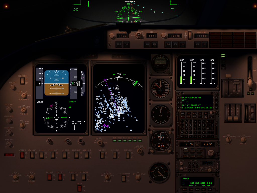
This is a feature I looked at putting into X-Plane 9, but it turned out that it affects so many different parts of the sim (and has to be done all-or-nothing) that it got kicked to v10. Consider these two pictures of the default B777 (the lighting was not adjusted, only the time of day):
The night image looks pretty, but what’s wrong with the day image? The answer is: the small panel post lights in the night image are still casting a fair amount of light in the day image. And the result looks silly. But why?
The answer is: in real life your pupils would contract in the sun, letting in less light. The sun is really rather bright, so the daytime panel would still look normal, but the apparent power of those posts lights would be a lot less, because your eyes are less sensitive. In other words, the relative strength of the sun and post lights is wrong in the second image.
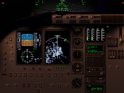
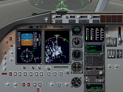
Computer monitors don’t have a huge dynamic range for how much brightness they can put out. So we can’t hope to display the absolute brightness of the scene correctly. Instead we need to make everything brighter at night (to simulate your night vision) and dimmer during the day, like this:
In this set of images, the night image is matched precisely to the previous one, but as the sun comes out, the apparent brightness of all lit textures has been scaled down to simulate the effect of your eye becoming less sensitive due to the flood of sunlight.
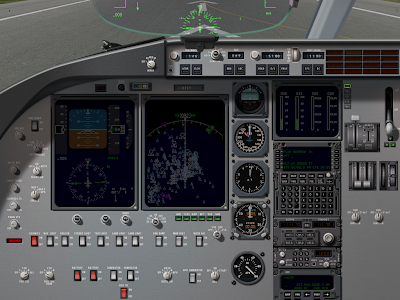
What’s good about the compensated image is that the weird artifacts from the post lights are gone; the relative strength of the post lights is really low in relative terms.
What happened to the EFIS and moving map? The answer is that they too are not as apparently bright relative to the sun as they would be at night.
There is one hitch here: plenty of real airplanes have light sensors for various avionics; the avionics will automatically turn up their brightness during the day. So it is possible (I am no expert on the 777) that in the real plane, as the sun rises, you might not have to adjust your instrument brightness; the sensor would do it for you. The pictures above illustrate what you would see if no automatic adjustment is made.
Auto-adjustment presents a challenge: currently two wrongs make a right. We don’t auto-adjust the brightness of instruments, but we don’t simulate the apparent visual brightness relative to the sun, and the result are instruments that look adequately bright at all times of day without user adjustment.
I think in the productized version of this feature, authors will have two options for anything lit:
- Tie the lit instrument/texture to an auto-adjusting rheostat (e.g. brightness 1 + auto adjustment) or
- Tie the lit instrument to the “raw” rheostat (e.g. brightness 1).
The tricky part will be finding the right mapping for legacy airplanes into the new system.
I sometimes get questions from authors considering how much to rely on a 2-d panel mapped to 3-d via the panel texture vs. a true 3-d panel. I can’t comment on what will look best, but I can comment on the relative performance characteristics of both techniques, and the answer might surprise you: in some cases you’ll get better performance by modeling directly in 3-d.
The 2-D Way
When you use the panel texture to make an object, X-Plane goes through a lot of steps to create the final result:
- Your panel has to be rendered in 2-d. We atlas your panel textures, but we don’t necessarily order them optimally – we don’t know the optimal order. Each generic instrument is at least one batch, perhaps even two. Those batches have very low vertex count, and the vertices are stored non-optimally on the CPU. There may be a fair number of texture changes between instruments.
- If you use ATTR_cockpit_region, we then go back and do the same thing…again! Why? Well, we need your panel’s raw color (“albedo” to graphics nerds) and the emissive light given off by anything self-lit separately, so that we can do correct 3-d lighting.
- Both of these are rendered to an off-screen texture that the video driver will feeel obligated to preserve at all costs, putting pressure on VRAM.
- Only when all that is done do we begin drawing your object, with the usual batches to change to panel texture and change back, perform animations, etc.
If this seems expensive, that’s because it is. Periodically users send me airplanes to look at their performance, and lately I’ve been seeing a lot more problems with 2-d panels (that fuel 3-d cockpits) being the performance bottleneck, not the 3-d modeling itself.
The 3-d Way
What if we want to go 3-d? Well, we’re going to “eat” a lot more of what your 3-d pit already has:
- You’ll need a lot more animations to move all of those parts.
- You’ll need new batches with ATTR_lit_level to dial up and down various lighting levels.
But you do get some advantages:
- Geometry in objects is processed about as optimally as we possibly can. All of that work we’ve done on the rendering engine to make OBJs fast is available in your cockpit. So you can increase 3-d detail ‘for free’.
- Your lit geometry can be drawn in a single pass (we don’t need to prepare two separate lit textures). So for example a needle would take three batches via the panel-texture route (a batch to rotate the needle for albedo, a second batch to draw the rotated night needle, and a third batch to draw the resulting texture in 3-d) but only one if you use the OBJ directly.
- Since you organize your textures for OBJs, you can guarantee that all of the cockpit stuff is together, saving texture thrash.
- You can use normal maps to add per pixel detail to your cockpit; panel textured geometry cannot be normal mapped.
A Balancing Act
Given the high cost of panel texture relative to native OBJ drawing, you’d think going native OBJ would be a no-brainer, right? Well, not quite.
A needle is an easy case: you can model a needle using a rotation animation, so your implementation in an OBJ and our generic instrument are quite similar. Same with the throttle lever generic instrument.
But what about a “glass pie indicator”? What about a moving map? What about a rotary?
There are some generic instruments that have “movement” for which there is no equivalent OBJ technique. With these generics, the generic instrument/panel code may be able to render the generic quite a bit more directly than your OBJ can simulate the same effect.
This is my suggestion on a cut-off: if you can directly model a generic instrument with an OBJ (needles, throttles, and other “simple moving things”), consider 3-d. If you would have to use a lot of extra texture space, copies of your mesh, or a lot of show-hides, use the panel texture.
Your goal should not be to eliminate the use of panel texture. But if you can cut panel texture down to a single 1024 x 1024 region from a larger area, you’ll probably see a performance win or a reduction in your airplane’s system requirements.
Performance Test First
Final thought: before you invest months in a complex cockpit design, mock up the “work-load” X-Plane must do and performance test it! For an OBJ, simply make one moving instrument and duplicate the mesh to get the number of expected animations. For the panel, drag out a bunch of instruments, make custom textures and just paint junk into them with photoshop. The goal is to make X-Plane do the same amount of work as it will in the final version. Then fly your test panel on target computers and observe performance.
There is no need to use the 3-d panel if you only want 3-d cockpit.
That might be the most counter-intuitive statement in the entire universe. Let’s break it down and see what’s going on. Originally we had the 2-D panel. The 2-D panel was where you put your instruments for interior views. When 3-d cockpit support was added, the 2-D panel was used to create the panel texture – that is, the instruments texture for the 3-D cockpit.
Thiat worked for a while, but as handles became more complex, screens became larger, and as 3-D cockpits became a more complex, authors started to run into the system’s limitations. If the author wanted to create a huge panel, then the panel texture for the 3-D cockpit was huge. Furthermore, texture space for the instruments in the 3-D cockpit was wasted because the 2-D panel had to have windows on it.
With X-Plane and 9 we added the 3-D panel to fix these problems. The 3-D panel is a second panel whose sole purpose is to provide instruments as a texture for the 3-D cockpit. When you have a 2-D panel and a 3-D panel, the 2-D panel is used to draw the panel in 2-D viewing modes and 3-D panel is used only to create the panel texture for the 3-D cockpit. With this setup the 2-D panel can be huge, and the 3-D panel can be small and compact with no windows.
The 3-D panel solves a second problem as well. Often the overhead panel is drawn in perspective on the 2-D panel this perspective view is useless for texturing a true 3-D cockpit. With a 2-D panel and a 3-D panel, the author can draw the overhead in perspective for the 2-D panel, and orthographically for the 3-D panel.
Now here’s where things get complicated: if an airplane has no 3-D panel the 2-D panel is used for both the 2-D view and the 3-D cockpit. But some airplanes have only a 3-D cockpit. In this case, there is no reason to use the 3-D panel at all. You can simply use the 2-D panel for texturing the 3-D cockpit and not worry about the user seeing it; in a 3-D only plane the user will only see the panel as a texture for the 3-D cockpit.
This setup is confusing in name: how can you have a 2-D panel used for a 3-D cockpits? But it is an allowed configuration. In fact, it was the only configuration allowed in X-Plane 8.
In summary: a 3-D cockpit can use the 2-D panel or 3-D panel as its panel texture. If an airplane has no 2-D panel, then the 2-D panel can be used for the 3-D cockpits without problems. In this situation and there is no need for a 3-D panel.
(It might be better to think of the 2-D panel and three panels simply add his two panels so that you can have two different versions of the panel. The names to the panel and 3-D panel are really just labels.)
X-Plane doesn’t natively and directly support popup panels, but that doesn’t mean you can’t pop them up. Generic instruments have a dataref-driven set of show-hide fields. (The “filters”.)
Now what you might not have realized is: groups have filters too! So you can hide an entire group with one filter, and you can put premade instruments in the group.
So…even though the FMS is a premade instrument with no filter fields, by grouping it you can show and hide it.
Important: the backgrounds of instruments are not shown or hidden. So if you want to do this, customize the FMS to have a transparent background, and use a generic rotary to put a real background behind it. The rotary goes in the group, and thus it can show and hide.
One more tip: clicking in 2-d goes through one instrument to another, for historical reasons. So if you pop up an instrument, you might want to hide the instruments it popped up over so clicks don’t affect them.
A quick tip to anyone using OpenGL and a plugin to make custom instruments. (The most common case of this I can imagine is customized glass displays, where it may not be practical to use 10,000 generic instruments, and the display being emulated is basically a computer display.)
OpenGL is not pixel exact, its per-primitive anti-aliasing (e.g. draw me a smooth line) is inconsistent and weird, and you probably won’t have full-screen anti-aliasing on your panel. (FSAA is out of your control, as X-Plane sets up the panel render.
For this reason, I recommend “texture anti-aliasing”. Basically in this technique you draw everything as rectangles, – for your lines, you use textures that have alpha at the edge. The linear intepollation of the texture forms the anti-aliased edge.*
For a detailed examination of the problem, I recommend this page. (arekkusu is a freaking genius and his treatment of the problem is very thorough!) I have also tried to explain how the hell OpenGL decides what it’s going to draw here. There are a few important cases where you can be pretty sure about what OpenGL will draw, and a lot of cases where you’re playing pixel roulette.
The “texture” technique also has the advantage that it leads nicely into the use of texture artwork. For example, if you need a line with an arrow-head, well, you’re already drawing a line as a textured rectangle with pixels in the center and alpha on the sides. Just ask your artist to draw an arrow-head in photoshop!
* Texture FSAA actually produces better results than FSAA (with non-AA pixels). The reason is that FSAA produces a finite number of intermediate alpha levels. The number of finite levels depends on the FSAA scheme, but it is always discrete levels, hence 16x FSAA looking better than 2x. By comparison, when we use textures, we get a smooth linear blend between our transparent and opaque pixels, giving us the smoothest possible anti-aliasing.
Javier posted a video of his CRJ on the dev list today. I have not tried the plane, but there is no question from the video that it looks really good. What makes the video look so nice is the careful management of light. Part of this comes from careful modeling in 3-d, and part of it comes from maxing out all of X-Plane’s options for light.
But…what are the options for light on an airplane? I don’t know what Javier has done in this case, but I can give you a laundry list of ways to get lighting effects into X-Plane.
Model In 3-D
To really have convincing light, the first thing you have to do is model in 3-d. There is no substitute – for lighting to look convincing, X-Plane needs to know the true shape of the exterior and interior of the plane, so that all light sources are directionally correct. X-Plane has a very large capacity for OBJ triangles, so when working in a tight space like the cockpit, use them wisely and the cockpit will look good under a range of conditions.
You can augment this with normal maps in 940. Normal maps may or may not be useful for bumpiness, but they also allow you to control the shininess on a per-pixel basis. By carefully controlling the shininess of various surfaces in synchronization with the base texture, you can get specular hilights where they are expected.
The 2-D Panel
First, if you want good lighting, you need to use panel regions. When you use a panel texture in a 3-d cockpit with ATTR_cockpit, X-Plane simply provides a texture that exactly matches the 2-d cockpit. Since the lighting on the 2-d cockpit is not directional, this is going to look wrong.
When you use ATTR_cockpit_region, X-Plane uses new next-gen lighting calculations, and builds a daytime panel texture and a separate emissive panel texture. These are combined taking into account all 3-d lighting (the sun and cockpit interior lights – see below). The result will be correct lighting in all cases.
Even if you don’t need more than one region and havea simple 1024×1024 or 2048×1024 3-d panel, use ATTR_cockpit_region – you’ll need it for high quality lighting.
The 2-d panel provides a shadow map and gray-scale illumination masks. Don’t use them for 3-d work! The 2-d “global lighting” masks are designed for the 2-d case only. They are optimized to run on minimal hardware. They don’t provide the fidelity for high quality 3-d lighting – they can have artifacts with overlays, there is latency in applying them, and they eat VRAM like you wouldn’t believe. I strongly recommend against using them as a source of lighting for a 3-d cockpit.
To put this another way, you really want to have all global illumination effects be applied “in 3-d”, so that the relative position of 3-d surfaces is taken into account. You can’t do this with the 2d masks.
The 2-d panel lets you specify a lighting model for every overlay of every instrument – either:
- “Mechanical” or “Swapped” – this basically means the instrument provides no light of its own – it just reflects light from external sources.
- “Back-Lit” or “Additive” – this means the instrument has two textures. The non-lit texture reflects external light, and the lit texture glows on its own.
- “Glass” – the instrument is strictly emissive.
You can use 2-d overlays not only for instruments but also to create the lighting effect within instruments, e.g. the back-lighting on a steam gauge’s markings, or the back-lighting on traced labels for an overhead panel.
2-d overlays take their lighting levels from one of sixteen “instrument brightness” rheostats. You can carefully allocate these 16 rheostats to provide independent lighting for various parts of the panel.
The 3-d Cockpit
The 3-d cockpit allows you to specify 3 omni or directional lights. These can be placed anywhere in the plane, affect all interior objects, and can be tinted and controlled by any dataref. Use them carefully – what they give you is a real sense of “depth”. In particular, the 3-d lights are applied after animation. If a part of the cockpit moves from outside the light to into the light, the moving mesh will correctly change illumination. This is something you cannot do with pre-baked lighting (e.g. a _LIT texture).
Finally, ATTR_light_level is the secret weapon of lighting. ATTR_light_level lets you manually control the brightness of _LIT texture for a given submesh within an OBJ. There are a lot of tricks you can do with this:
- If you know how to pre-render lighting, you can pre-render the glow from a light onto your object into your _LIT texture, and then tie the brightness of the _LIT texture to a dataref. The result will be the appearance of a glow on your 3-d mesh as the light brightens. Because the lighting effect is pre-calculated, you can render an effect that is very high quality.
- You can create back-lit instruments in 3-d and link the _LIT texture to an instrument brightness knob.
- You can create illumination effects on the aircraft fuselage and tie them to the brightness of a beacon or strobe.
There are two limitations of ATTR_light_level to be aware of:
- Any given triangle in your mesh can only be part of a single ATTR_light_level group. So you can’t have multiple lighting effects on the same part of a mesh. Plan your mesh carefully to avoid conflicts. (Example: you can’t have a glow on the tail that is white for strobes and red for beacons – you can only bake one glow into your _LIT texture.)
- ATTR_light_level is not available on the panel texture. For the panel texture, use instrument brightness to control the brightness of the various instruments.
I have a sample plane that demonstrate a few of these tricks; I will try to post it on the wiki over the next few days.
In Plane-Maker you will see that there are two “glass” lighting modes for instruments – one called “glass” and the other called “glass (translucent)”.
What’s the difference? The difference is how they respond to their lighting rheostat being turned down.
- Glass becomes dim by mixing the RGB colors of the overlays toward black.
- Glass (tranlsucent) becomes dim by mixing the alpha channel of the overlays toward transparent.
Which one do you want? It depends on what you are doing. The rules I suggest are:
- Use “glass” if you are using the layer as a “mask” to block elements behind it.
- Use “glass (translucent) if you are using the layer as an “overlay” to draw on top of other elements.
Posted in Panels
by
Ben Supnik |
X-Plane’s panel system does not have true “masking” based on a bitmap. You can clip an instrument to its rectangular region, but most masks are made by overlaying another layer or instrument on top of the moving parts. Examples include the circular mask for the moving map and the outside of the artificial horizon dial.
If you are using ATTR_cockpit then what you see in the OBJ is just like what you see in the 2-d panel, and the masking problem is simple: pick a mask that matches your background. In particular, if the back of the panel is black, your mask must be black; if the back of your panel has a gradient, the mask must contain a copy of a slice of the gradient.
But there are two cases where this rule does not work the way you might expect.
Masks for 2-d Spotlights
The 2-d spotlight textures (panel-2, panel-3, etc.) have a strange property: they light the background of the panel (the “burned in layer”) per-pixel but the overlays are lit per vertex. This is a cheat to keep the frame-rate high.
Normally this is not a problem – the moving parts are small and look different enough from the background that the lighting mismatch is not visible. But if you have a mask in the 2-d panel and spot lights, it will not match!
Unfortunately there is not much you can do about this. The only thing you can do is to keep the spotlight color uniform over the entire mask region.
Masks for Cockpit Regions
When you use ATTR_cockpit_region, the lighting model for your 3-d cockpit changes: instead of drawing the panel (as you saw it in 2-d), X-Plane calculates the albedo (day-time) and emissive (“_LIT”) components of the panel separately and then combines them with real 3-d lighting.
The good news is that the spot light problem is no longer a problem. Since the spot lights are 3-d and are applied to these final “panel textures”, a mask that matches the background will blend perfectly.
But in order to mask, you need to know which part of the panel texture you are masking (albedo or emissive!). If you are masking the albedo texture (e.g. a mechanical artificial horizon), create a mask that looks just like the panel background.
But for a glass instrument, the moving parts go into the emissive layer. Your mask must be pure black! Where did I get that from? The emissive layer adds light to the object. Black is an absence of adding light. So pure black ‘erases’ any light-only elements (which include all glass EFIS instruments, etc.).
One nice thing about this strategy: you can build a custom glass instrument (with a black mask) and put it over any background. This means you can reuse your art assets no matter how they are positioned on the panel.
With X-Plane 930 beta 8, we finally integrated the latest version of Max’s Cessna 172 SP. Grab the new beta and try it – he’s added a number of new features that demonstrate some of the newer X-Plane 9 airplane features.
- Real 3-d lighting in the 3-d cockpit. Note how the map light tends to illuminate only some of the cockpit as it fades out.
- 2-d back-lighting on all of the major steam gauges.
- A bunch of parts can now be dragged in 3-d, including the door handles. This is done via manipulators.
- Walls! In 3-d cockpit viewer mode you won’t be able to leave the airplane until you actually open the doors. The cockpit viewpoint is constrained.
- The model has the glass parts separated out for correct shadowing, and the glass works correctly from all viewpoints.
- Panel uses cockpit regions for accurate lighting.
The cirrus jet has been similarly updated. I plan to use the Cessna for a series of tutorials showing how to use these recent X-Plane features.
What is the difference between a dataref and a command? They serve different purposes in X-Plane, but it’s easy to get them confused, especially because the names can look so similar. If you only take one thing away from this comparison, it should be:
- Datarefs are information.
- Commands are actions.
Datarefs
A dataref is a single bit of published information. For example, the user’s indicated airspeed, as seen by the pilot, is a dataref, stored in:
sim/cockpit2/gauges/indicators/airspeed_kts_pilot
Datarefs have names that do not change. Datarefs made available by X-Plane start with sim/ while datarefs made available by plugins start with another prefix. Datarefs have been in X-Plane since the release of the plugin system in version 6.70.
You can always read a dataref, but sometimes you can change it. Trying to change a dataref usually has one of three actions:
- If the dataref is not writable at all, nothing happens.
- If the dataref is writable, it will change.
- Sometimes a dataref may be writable, but only after changing some other sim configuration. For example, you can only “write” to the control surface deflection datarefs after setting the control surface override dataref to 1. (If you don’t set this override, X-Plane will constantly write its own ideas of the control surface positions to the control surface datarefs and your changes will be lost.)
You can read and write datarefs:
Commands
A command is an action that the sim can take on your behalf. For example, the command
sim/autopilot/altitude_arm
arms the autopilot for altitude hold.
Like datarefs, commands have permanent names, starting with sim/ for X-Plane or other prefixes for plugins. Commands have been available in X-Plane since version 9.0.
You can always actuate a command, but there is no guarantee that it will do anything. For example, the engine starter command won’t start the engine if the plane has electrical starters and the battery is dead.
You can use commands by:
Plugins
Plugins can add both new datarefs and new commands to the sim. Plugins can also change the behavior of all built-in sim commands, and can change the information in some datarefs.
Where Do I Find Datarefs And Commands
X-Plane’s default commands and datarefs are listed in the text files Commands.txt and Datarefs.txt in the Resources/plugins folder. (Note: providing the command list is new to X-Plane 930.) The dataref list is also available on the X-Plane SDK Wiki.
Up next: when should I use a command and when should I use a dataref?