I want to revisit the question of whether (and how) the livery system should be extended. In particular, it is my opinion that the livery system should not be extended to allow:
- Replacement of OBJs used for modeling the airplane or cockpit.
- Alternate or modified ACFs*.
- Generally, the livery system shouldn’t be used for changing the plane’s behavior – it’s just paint!
I have commented previously in three parts that the livery system is meant to make easy the integration of third party paint without (a) violating copyright, (b) requiring byzantine installation instructions or (c) requiring the painter and original author to coordinate. I have received requests from a number of very talented airplane authors, asking for the livery system to cover a whole range of new features, most of them involving configuration. I will try to explain in this post how I think should should be handled.
First, to be clear: an aircraft file is the .acf file that contains the X-Plane specific data needed to simulate the plane; the aircraft package is the folder containing that .acf file. A livery is a painting scheme for the 3-d model of the airplane, and a configuration is an instance of a plane with certain features, e.g. with or without G1000, with P&W; vs. Rolls Royce engines, etc.
Configurations of an aircraft should be created by putting more than one aircraft file
(.acf) in a single aircraft package. Because the graphic and sound resources needed for the aircraft are accessed relative to the .acf file, you can build a family of aircraft with some common aspects and some unique aspects to each plane.
Files used by an aircraft fall into three broad categories:
- Files found by a fixed formula using the .acf name, e.g. be20_paint.png. Let’s call these “file-specific”.
- Files found by a fixed formula without using the .acf name, e.g. the contents of the aircraft plugins folder. Let’s call these “package specific”.
- Files that are explicitly named in the .acf file, like airfoils and OBJs. Let’s call these “flexible” (since this naming scheme could be used in any way).
Here’s how the important files in an aircraft break down:
- The aircraft paint scheme is file specific.
- The aircraft panel background is package specific (but you can effectively have each file use a different panel background by setting the panel type differently for each plane).
- Sounds are actually either, which effectively makes them flexible. Non-generic instruments are package-specific.
- Objects, generic instruments and airfoils are flexible.
In other words, if you can live with duplicating your aircraft paint files (and I suspect that in most cases either the plane is built by objects, or the modifications in each configuration warrant paint changes anyway), then every other feature can be set to package or file specific, allowing you to build a group of aircraft around a single real-world plane.
Now if there are aspects of a multi-configuration aircraft package that don’t work right now, we can look at possible changes to the sim to make this work. But it appears to me that just about everything necessary to make multiple configurations is already available in the sim now.
As a final note, the question here (livery vs. multi-file aircraft pack for configurations) is one of file formats, and thus of data organization and contracts between authors and programmers. It is not a question of user interface. The user interface can be reshaped to make multi-aircraft packages look like liveries, or liveries look like multi-aircraft packages. But I suspect that most of the interest in extended liveries is on the file-format side.
* The one exception for liveries is the tail number — given the strange state where the tail number, as painted into the livery, is also written into the ACF, it wouldn’t be bad to be able to override this property. Some people are already doing this using plugins.
A hidden detail of my previous post on variation and terrain textures: variation for flat textures was implemented using more triangles in the DSF in X-Plane 8, but is implemented in a shader in X-Plane 9. This means that you don’t get this feature in X-Plane 9 if shaders are off.
My guess is that this is perfectly acceptable to just about every user.
- If you don’t have shaders, you have something like a GeForce 4 or Radeon 8500, and are fighting for frame-rate. In this case, not paying the price of layer-based variation is a win.
- If you have shaders, you’re getting better performance because the shader creates variation more efficiently than the old layering scheme did.
This kind of move of a feature to the GPU can only happen at major versions when we recut the global scenery, because (to utilize the benefit) the DSFs are recut with fewer (now unneeded) layers. So features aren’t going to mysteriously disappear mid-version.
I do have a goal to move more layering-type features to the GPU for future global scenery renders. There are a number of good reasons:
- DSF file size is limited – we have distribution requirements on the number of DVDs we ship. So DSF file size is better spent on more detailed meshes than on layers.
- GPU power is increasing faster than anything else, so it’s good to put these effects on the GPU – the GPU is still hungry for more!
- If a feature is run on the GPU, we can scale it up or down or turn it on or off, for more flexible rendering settings on a wide variety of hardware. A feature baked into the DSF is there for everyone, no way to turn it off.
My hope for the next render is to (somehow) move the cliff algorithm (which is currently done with 2-4 layers) to the GPU, which would shrink DSFs, improve performance, and probably create nicer looking output.
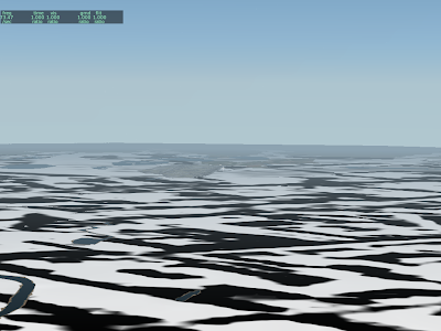
In my previous post I discussed variation as a way to hide the artifacts of land use texturing. Now we can talk about this bug.
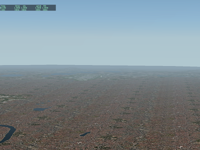
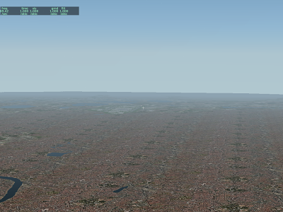
What are these weird artifacts that show up over the terrain when shaders are on? Well, they should (and will in 930) look like this:
But what’s going on? The answer is auto-variation.
In X-Plane 8, variation is created by using multiple layers, each one applying a texture at a different offset. This technique works on a wide range of hardware, but is inefficient – it causes overdraw (which we know is
very bad).
So in X-Plane 9 I replaced this layer-based variation with a pixel shader algorithm. This means less information in the DSF (which means smaller DSFs, faster loading and less RAM use), but it also means variation is only visible to those with shaders. Having the pixel shaders create variation dynamically on the GPU is called “auto-variation” (and is invoked via the AUTO_VARY command in a .ter file).
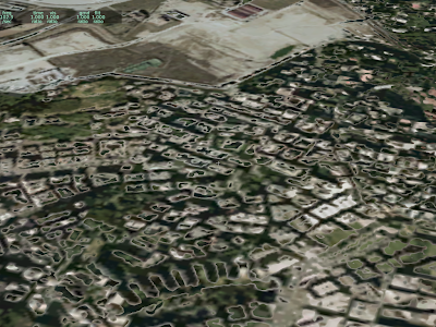
The artifact above was a bug in the auto-variation shader. With the code now fixed (the 930 patch will contain the fix), here are some images of how it is supposed to work:
Here we have the texture in question, at two different offsets.
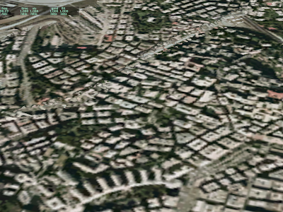
This black and white texture is the “mixing mask” used to select which offset to use.
And this is the final result.
There is a little bit more disruption in the columns of green park.
I saw a post about this on X-Plane.org…authors sometimes try to make a vehicle (a car, truck, etc) modeled via an OBJ “drive around” using animation translate commands. The problem is that sometimes the objects disappear. Here’s what is going on:
X-Plane uses a bounding sphere to decide whether to draw an object. The bounding sphere is the smallest sphere X-Plane can fit around the entire object; if the sphere is on screen, the object is drawn (even if the object itself isn’t on screen). We do this because we can test whether the sphere is on screen very quickly.
But what if the object has animation? X-Plane attempts to guess how animation might affect the sphere by looking at animation commands and making the sphere a bit bigger where animation might move the object outside the sphere. This process works, well, rather poorly. In particular, X-Plane doesn’t know exactly how your datarefs will change. This results in two error cases:
- If X-Plane assumes the animation is more drastic than it really is, we make the sphere too big. The object will then be drawn even when it is not on screen (because the sphere is on screen because it is too big). This case hurts fps but does not cause objects to disappear.
- If X-Plane assumes the animation is less drastic than it really is, we do not make the sphere big enough, and sometimes the object “disappears” because the object is on screen but the (too small) sphere is not.
Now let’s apply this to objects that are driving around. Usually this is done via a translate animation command where datarefs feed the object’s position.
X-Plane estimates the effects of a translate animation using the largest and smallest key frame values. But the animation engine will extrapolate beyond these key frames. So consider these three cases:
- As your dataref goes from -1 to 1, you translate by +/- 1 meter. In this case, the bounding sphere will be increased in radius by one meter.
- As your dataref goes from -25 to 25, you translate by +/- 25 meters. In this case, the bounding sphere is increased in radius by twenty five meters.
- As your dataref goes from -1000 to 1000, you translate +/- 1 kilometer. In this case, the bounding sphere is increased in radius by 1000 meters.
Note that in all three of these cases, the animation works exactly the same! But by using different dataref and value extremes, X-Plane’s estimate of the effects of the animation (and its change to the boundign sphere) can be quite different.
So…if you animate an object and it disappears, it is probably because the bounding sphere has not been increased, perhaps because a translation animation is being sent values outside its minimum and maximum values.
The problem is of course that to have an object “roam” over a large area, it must have a very large bounding sphere, which means it is being drawn a lot more than necessary.
More ranting on the question of whether a file format is based on factual information or not. For the sake of taxonomy, let’s call this:
- Factual. The file format aims to capture “real world” information. The file spec is thus written against real world norms. Example: a runway is described by the location of its centerline at its threshholds, the type of aproach lighting fixtures, and the material it is built out of. This is all fact that can be verified by going to the runway and measuring it (while trying to avoid 747s).
- Artistic. The file format gives authors a creative platform to create “stuff”, e.g. an image, a model; the file format dictates how client applications might interpret that “stuff”. Example: OBJs are artistic – it describes what affect on drawing the various bits of the OBJ file have.
Apt.dat is actually a hybrid format – most of it is factual, with one glaring exception: pavement surface areas.
Pavement surface areas are simply an overlapping pile of bezier polygons with holes. There are multiple ways to create a given layout, and you couldn’t make an argument that one is “more factually correct” than the other.
Artistic file formats give us a way to be open-ended, and so they are particularly useful for problems that we cannot solve in a practical manner using factual file formats. When we worked on the apt.dat 850 format, I clung to a 100% factual approach for as long as I could, hoping to be able to truly describe “ground truth” about airport pavement. What I found in the end was that real world instances of airport pavement are so varying and weird in real life that almost any factual approach would fail to correctly model important real-world airports. So we punted and simply said “put pavement wherever you want, make it look nice.”
The result of going artistic instead of factual is two-fold:
- The taxiway data in the apt.dat file is less broadly useful to a wide range of client applications; you might be able to infer some aspects of the real taxiways from the data, but the taxiway shape has very little structure to it.
- You can model just about anything you can dream of – there really aren’t any limits.
That taxiways are “artistic” will probably always bug me a little bit from a theoretical viewpoint, but I think there is no question that this was the only practical standpoint.
Final thought: factual file formats are usually not precomputed – that is, if we have a list of runways described by their real-world properties (and not modeled as a collection of textured triangles) then there is probably work that still needs to be done to make the file useful for X-Plane. (That work is done by X-Plane’s file loading code.)
Okay – I’m OOTO for a while – see you before thanksgiving!
/ben
Previously I have blogged about a key choice in file format and scenery system design: will the file format be “specification based” or “reality based”.
Specification based: the format has an exact interpretation of the data. OBJ is an example of this…the format describes triangles and there is only one interpretation of what that triangle could be.
Reality based: the format models real-world concepts; the correct interpretation is “as close to the real world as possible.” The nav.dat file is like that.
I have been reading the OpenStreetMap Wiki and hit upon something I didn’t realize: you can’t use copyright to protect a derived work from a file that simply contains a list of facts!
Now I am a programmer – I am used to writing code, slapping a copyright notice up top, and assuming that it’s now mine…heck, I’m the one getting carpel tunnel from typing it out. But consider the nav.dat file; it contains a giant list of frequencies for navaids. It’s a fact that the BOS VOR is 112.7. Is my mentioning of that fact in this blog a derived work of the nav.dat file? Of course not, and it’s a good thing too because otherwise we wouldn’t be able to state facts without IP conflicts.
The OSM guys believe that they need to change their license to something weirder than the CC-BY-SA license they have now because the CC license uses copyright, you can’t copyright facts, and OpenStreetMap is really just a huge collection of facts.
Now at this point I’ve written six paragraphs too many without the obligatory “I am not a lawyer.” I am not one. And I must admit, my biggest concern with all of this is that it gets confusing and hard to interpret, and I’d be perfectly happy if there were only 3 or 4 licenses out there for everyone, you’d pick your favorite flavor, and everyone would know what it means.
Suffice it to say, it never occurred to me that a criteria of a file format might be “protectability” – that is, does the file format allow an author to specify something other than facts, so that it is elligible for copyright protection?
If you are an author, the good news is: pretty much all of our file formats would meet that criteria:
- OBJ and DSF are essentially 3-d modeling containers (DSF is just a damned wierd one).
- Images are copyrightable, so that takes care of your textures.
- Plugins are code, clearly copyrightable.
- ACF files contain, among other things, 3-d models, see the first point.
- Apt.dat would be the format most at risk of “factualization”, but I think you could argue that the arrangement of bezier curves and attributes is more of an artistic 3-d model than a statement of fact.
But who knows, I am not a lawyer.
(Oh yeah, this whole article is written from an entirely US-centric viewpoint…I am even less qualified to speak of such things outside the US than I am here at home.)
The apt.dat 850 file format defines a polygonal “airport boundary”. But what exactly does it do? It does different things when creating DSFs and when rendering them.
Inside X-Plane it has relatively little effect:
- It is one of many elements that counts toward the land area that will be flattened. (Runways and taxiways are also used.)
- We do not actually render any special terrain or fences.
The airport boundary has more of an effect during scenery creation.
- If an airport has an airport boundary, we do not calculate the airport’s boundary ourselves – instead f we use the specified boundary.
- All land intersecting the airport boundary is turned to airport terrain.
- The DEM is flattened within the airport boundary to reduce the slope of high frequency bumps.
There is one aspect of airport creation that the airport boundary is not involved in: filling in water to make land under runways. When we create an airport, we actually calculate three boundary polygons:
- The inner ring is closest to runways and taxiways (very close) with very little simplification. It is filled in with land if it is wet.
- A second ring slightly farther from runways and taxiways is also filled in with land if it is wet.
- The outermost ring is a lot farther out, but does not fill in Water. This is the ring that the airport boundary can replace.
Why do we need two inner rings? Well, if an airport is next to the water but not at sea level, we need to induce two sets of mesh points, the outer ones which drop down to sea level and the inner ones which are at airport level. You can see the importance of this at KLGA, where one of the runways dropped to sea level at its midpoint in version 8, but not version 9.
Since the airport boundary polygon provides only one ring, it cannot be used for this purpose. At some point in the future, we might use the airport boundary for rings 2 and 3, or use a smaller version of the airport polygon for rings 1 and 2.
For now, my recommendation is: the airport boundary should trace out the entire airport premesis, not including water.
If you read the original X-Plane scenery web pages, you’ll see references to two file formats:
- DSFs – the files we distribute scenery in.
- XES – the “X-Plane Editable Scenery” file format, which you won’t see very much of.
Here’s the story:
When I was first working on the scenery system design, we decided on a pre-processed approach, which implied two types of file formats: pre-baked (editable source data) and post-baked (distributable finished scenery). XES is a GIS container format for the source data.
When we create the global scenery, the process is something like this:
- Import lots of data from multiple sources in multiple formats, so that it is all in one giant tile in our format.
- Process the data, deriving new information (like terrain type) from existing data (like slope) and fixing problems (like bumps on runways).
- Export the data as a DSF, which involves additional conversions (such as converting generic road types to x-plane roads) and DSF encoding.
We keep our raw data partly in XES format, and partly in the original raw format, depending on how slow the importer is – some vector formats are very slow to import (or are not already tiled), so we preconvert to XES. Other formats, like SRTM, are so easy to import quickly that we just use the data as is.
If you have ever tried to use MeshTool, you may have used XES files yourself – the landuse and climate data that MeshTool needs are saved as XES files – it’s an easy way to encode a few variable sized raster maps with portable enumeration encoding.
WED does not use XES files – when I started work on WED, I realized that the XES container format was too GIS oriented and not application-oriented, so I created a file format particular to WED. WED will continue to use .wed files, which can contain anything that WED can edit.
In the long term, I don’t see XES as being used by anyone except for LR internally; WED will continue to have a WED native format, and we will try to use common simple GIS formats for import/export – most likely SRTM hgt files for elevation and .shp (shape) files for vectors.
This thread on X-Plane.org sparked off quite the discussion. Now a lot of this is a discussion of when LR will have an overlay editor – there are a few overlay editing functions that Jonathan Harris’ excellent OverlayEditor apparently does not yet support, sparking this discussion.
(I am not saying that LR should rely on Jonathan to do an overlay editor. But I am saying that the complaints I hear about a lack of overlay editing go down when Jonathan’s overlay editor does everything that the file formats can do.)
But another part of the discussion focused on the problem of mesh editing. In particular, the basic terrain in a DSF is a fully baked output of a complex process that starts with higher level GIS input data. In other words, we start with a raster DEM, polygon coastline, apt.dat file, vector roads, and a bunch of config files and hit “bake” and a DSF comes out the other side, with a lot of processing.
This is very different than FS X, which integrates its data sources on the fly. Why did we choose a precomputed route for scenery? It has some pros and cons. (In understanding how we made these decisions, think back to what scenery was like with X-Plane 7 and ENVs and single-core machines.)
Performance
The main benefits of preprocessing scenery are performance related. When you process scenery data into the final scenery while flying, that computer power takes away from the rendering engine, thus cutting down fps. At some point you have a zero-sum game between how much cost there is to loading scenery and how complex the scenery integration can be; you have to pick very simple scenery integration algorithms to keep fps up.
(This is less of an issue as more cores become available, but is still a factor.)
When pre-processing, we can use algorithms that take minutes per DSF without affecting framerate.
Similarly, there might be scenery processing algorithms that improve fps by optimizing the output triangles – but do we have time to run these algorithms during load? With preprocessing we have all the time in the world because it happens once before the DVDs are burned.
Preprocessing also breaks a similar zero sum game between scenery data size and quality; the source data we use to make the scenery is a lot bigger than the 78 GB of DSFs we cut; if we had to ship the source data, we’d have to cut down the source data quality to hit our DVD limitations. With be-baking we could use 500 GB of source data without penalty.
Format Flexibility and Stability
The second set of benefits to preprocessing are flexibility benefits. (Consider the file format churn of the ENV days.)
– With a preprocessed scenery file, what the author creates is what the user sees – X-Plane does not go in and perform subjective integrations on the scenery later that might change how it looks in a negative way.
- There is no need to revise the scenery file formats to introduce new data sets, because new data sets and old are all processed to the same final DSF container format.
- A wide variety of mesh generation techniques can be employed because the mesh generation is not built into X-Plane. This is a flexibility that I don’t think anyone has really utilized.
- Changes of behavior in the scenery generation toolset can never affect existing scenery because that scenery is already preprocessed; this help compatibility of old file formats.
Integration Issues
There are some real limitations to a pre-processed format, and they are virtually all in the bucket of “integration issues” – that is, combining separate third party add-ons to improve scenery. In particular, in any case where we preprocess two data sources, we lose the opportunity for third parties to provide new scenery to replace one of those data sources and not the other.
Airport is the achilles heal where this hurts us most; while airport layouts are overlays and can be added separately to the scenery system, the elevation of the base mesh below the airport needs to be preprocessed. This is something I am still investigating – a tolerable fix that other shave proposed is to allow an overlay scenery pack to flatten a specific region regardless of the user setting (so an author can be assured of a flat base to work from).
Preprocessing does fundamentally limit the types of third party add-ons that can be done; with version 9 and overlay roads, we are getting closer to letting road add-ons be overlays (see this post).
It appears to me that integration isn’t the primary complaint about the scenery system (the primary complaint is lack of tools) but we’ll have to see once we have mesh editing tools (mesh recreation tools really) whether preprocessing still limits certain kinds of scenery.
Note that a lack of tools or a lack of tool capability is not an inherent limitation of pre-processed scenery. We have an incomplete tool set because I have not written the code for a complete tool set, not because it cannot be done.
(The complexity of writing base mesh editing tools is a function of the complexity of a vector-based base mesh – this is also not related to pre-processing per se.)
Tools
In the end, I think the question of tools is not directly tied to the question of pre-processing. Whether we have scenery that is processed by X-Plane or a preprocessing tool, we have the same issues:
- Good tools require an investment in coding user interface.
- The code to convert source data which users might want to edit (like a polygon that defines a lake) to data the simulator might want to use (like a list of 78,231 triangles) has to be written.
I don’t think either option (pre-processing or in-simulator processing) reduces the amount of work to be done to create a good toolset.
As a final thought, using scenery file formats that are “easier to edit” (e.g. a file format that contains a polygon for water rather than triangles) doesn’t make the total code for scenery tools + simulator any easier; it just moves the task of “processing” the scenery from the tools to the simulator itself.
Per-pixel lighting is something I hope to have in X-Plane soon. A number of other features will take longer, and quite possibly might never happen. This is the “pie in the sky” list – with this list, we’re looking at higher hardware requirements, a lot of development time, and potential fundamental problems in the rendering algorithm!
High Dynamic Range (HDR) Lighting
HDR is a process whereby a program renders its scene with super bright and super dark regions, using a more detailed frame-buffer to draw. When it comes time to show the image, some kind of “mapping” algorithm then represents that image using the limited contrast available on a computer monitor. Typical approaches include:
- Scaling the brightness of the scene to mimic what our eyes do in dark or bright scenes.
- Creating “bloom”, or blown out white regions, around very bright areas.
Besides creating more plausible lighting, the mathematics behind an HDR render would also potentially improve the look of lit textures when they are far away. (Right now, a lit and dark pixel are blended to make semi-lit pixels when far away as the texture scales down. If a lit pixel can be “super-bright” it will still look bright even after such blending.)
Besides development time, HDR requires serious hardware; the process of drawing to a framebuffer with the range to draw chews up a lot of GPU power, so HDR would be appropriate for a card like the GeForce 8800.
While there aren’t any technical hurdles to stop us from implementing HDR, I must point out that, given a number of the “art” features of X-Plane like the sun glare, HDR might not be as noticeable as you’d think. For example, our sun “glares” when you look at it (similar to an HDR trick), but this is done simply by us detecting the view angle and drawing the glare in.
Reflection Mapped Airplanes
Reflection maps are textures of the environment that are mapped onto the airplane to create the appearance of a shiny reflective surface. We already have one reflection map: the sky and possibly scenery are mapped onto the water to create water reflections.
Reflection maps are very much possible, but they are also very expensive; we have to go through a drawing pass to prepare each one. And reflection maps for 3-d objects like airplanes usually have to be done via cube maps, which means six environment maps!
There’s a lot of room for cheating when it comes to environment maps. For example: rendering environment maps with pre-made images or with simplified worlds.
Shadows
Shadows are the biggest missing feature in the sim’s rendering path, and they are also by far the hardest to code. I always hesitate to announce any in-progress code because there is a risk it won’t work. But in this case I can do so safely:
I have already coded global
shadow maps, and we are not going to enable it in X-Plane. The technique just doesn’t work. The code has been ripped out and I am going to have to try again with a different approach.
The problem with shadows is the combination of two unfortunate facts:
- The X-Plane world is very, very big and
- The human eye is very, very picky when it comes to shadows.
For reflections, we can cheat a lot — if we don’t get something quite right, the water waves hide a lot of sins. (To work on the water, I have to turn the waves completely off to see what I’ m doing!) By comparison, anything less than perfect shadows really sticks out.
Shadow maps fail for X-Plane because it’s a technology with limited resolution in a very large world. At best I could apply shadows to the nearest 500 – 1000 meters, which is nice for an airport, but still pretty useless for most situations.
(Lest someone send the paper to me, I already tried “TSM” – X-Plane is off by about a factor of 10 in shadow map res; TSM gives us about 50% better texture use, which isn’t even close.)
A user mentioned
stencil shadow volumes, which would be an alternative to shadow maps. I don’t think they’re viable for X-Plane; stencil shadow volumes require regenerating the shadow volumes any time the relative orientation of the shadow caster and the light source change; for a plane in flight this is every single plane. Given the complexity of planes that are being created, I believe that they would perform even worse than shadow maps; where shadow maps run out of resolution, stencil shadow volumes would bury the CPU and PCIe bus with per-frame geometry. Stencil shadow volumes also have the problem of not shadowing correctly for alpha-based transparent geometry.
(Theoretically geometry shaders could be used to generate stencil shadow volumes; in practice, geometry shaders have their own performance/throughput limitations – see below for more.)
Shadows matter a lot, and I am sure I will burn a lot more of my developer time working on them. But I can also say that they’re about the hardest rendering problem I’m looking at.
Dynamic Tessellation
Finally, I’ve spent some time looking at graphics-card based tessellation. This is a process whereby the graphics card splits triangles into more triangles to make curved surfaces look more round. The advantage of this would be lower triangle counts – the graphics card can split only the triangles that are close to the foreground for super-round surfaces.
The problem with dynamic tessellation is that the performance of the hardware is not yet that good. I tried implementing tessellation using geometry shaders, and the performance is poor enough that you’d be better off simply using more triangles (which is what everyone does now).
I still have hopes for this; ATI’s Radeon HD cards have a hardware tessellator and from what I’ve heard its performance is very good. If this kind of functionality ends up in the DirectX 11 specification, we’ll see comparable hardware on nVidia’s side and an OpenGL extension.
(I will comment more on this later, but: X-Plane does not use DirectX – we use OpenGL. We have no plans to switch from OpenGL to DirectX, or to drop support for Linux or the Mac. Do not panic! I mention DirectX 11 only because ATI and nVidia pay attention to the DirectX specification and thus functionality in DirectX tends to be functionality that is available on all modern cards. We will use new features when they are available via OpenGL drivers, which usually happens within a few months of the cards being released, if not sooner.)


