Sim/cockpit/autopilot/autopilot_state
The autopilot state dataref summarizes all state and mode information from the autopilot.
Summary of Values
The following table summarizes all bit-field values.
| Bit field (Decimal) |
Bit field (Hex) |
Name |
Axis |
Notes |
| 1 |
00001 |
Autothrottle Speed Engage |
Throttle |
When the pitch axis is NOT speed-by-pitch, holds airspeed or mach number by manipulating the auto-throttle servos. |
| 2 |
00002 |
Heading Select Engage |
Lateral |
Flies the selected magnetic heading. |
| 4 |
00004 |
Roll Hold Engage |
Lateral |
Holds the selected bank (roll) angle. |
| 8 |
00008 |
Speed-by-pitch Engage |
Vertical |
Holds the selected airspeed or mach number by manipulating pitch. Does not touch the throttle to do so. Note that when altitude is armed, this will be limited in pitch to the direction the pre-selected altitude is from the current altitude. For a true speed-by-pitch regardless of altitude, altitude hold must not be armed. |
| 16 |
00010 |
V/S Engage |
Vertical |
Holds the selected vertical speed. |
| 32 |
00020 |
Altitude Hold Arm |
Vertical |
Before X-Plane 8.11, altitude was “always armed” – that is, setting this would engage altitude immediately. In X-Plane 9.0, altitude was always armed. In 9.20 and 9.30, this was incorrectly mapped to “altitude engage” when written to. Now this correctly maps to the arm only. Note that an aircraft might still specify “altitude is always armed” in Plane Maker. |
| 64 |
00040 |
Flight Level Change Engage |
Vertical |
Speed-by-pitch in combination with altitude preselect armed. |
| 128 |
00080 |
Pitch Hold Engage |
Vertical |
Holds the selected pitch angle. |
| 256 |
00100 |
Nav Armed |
Lateral |
Arms tracker/coupler to track a nav source (VOR radial, localizer or GPS course). |
| 512 |
00200 |
Nav Engaged |
Lateral |
Tracker/Coupler tracks a nav source. Writable with overwrite – see below. |
| 1024 |
00400 |
Glideslope Armed |
Vertical |
Arms vertical track of a nav source (ILS glide slope or GPS glide path). |
| 2048 |
00800 |
Glideslope Engaged |
Vertical |
Tracks a vertical nav source (ILS glide slope or GPS glide path). Writable with overwrite – see below. |
| 4096 |
01000 |
VNAV Speed Armed |
Vertical |
Speed-by-pitch mode to achieve FMS-selected speed to climb or descend to VNAV altitude or MCP altitude, whichever is more restrictive. Armed below 400ft. |
| 8192 |
02000 |
VNAV Speed Engaged |
Vertical |
Speed-by-pitch mode to achieve FMS-selected speed to climb or descend to VNAV altitude or MCP altitude, whichever is more restrictive. Writable with overwrite – see below. |
| 16384 |
04000 |
Altitude Hold Engaged |
Vertical |
Starting with X-Plane 9.40, you can directly engage the autopilot in this mode. See below. |
| 32768 |
08000 |
TO/GA |
Lateral |
Since X-Plane 9.30. Holds wings level in take-off or go-around phase. |
| 65536 |
10000 |
TO/GA |
Vertical |
Since X-Plane 9.30. Holds pre-determined pitch in take-off or go-around phase. |
| 131072 |
20000 |
VNAV Path Armed |
Vertical |
Since X-Plane 9.40. Arms geometric descent. Use in conjunction with G1000 providing descent cues. |
| 262144 |
40000 |
VNAV Path Engaged |
Vertical |
Since X-Plane 9.40. Flies geometric descent. Use in conjunction with G1000 providing descent cues. Writable with overwrite – see below. |
| 524288 |
80000 |
GPSS Engaged |
Lateral |
Since X-Plane 11.10. Tracks GPSS regardless of HSI selected nav source. Use this to fly in LNAV mode while being able to arm Nav mode for localizer interception. |
| 1048576 |
100000 |
Heading Hold Engaged |
Lateral |
Since X-Plane 11.10. Holds Heading at the time of engagement, ignores heading bug. |
| 2097152 |
200000 |
Turn Rate Engaged |
Lateral |
Since X-Plane 11.30. Holds turn rate (as indicated by turn coordinator) instead of bank angle. |
| 4194304 |
400000 |
Track Engaged |
Lateral |
Since X-Plane 11.30. Holds magnetic ground track corrected for wind. |
| 8388608 |
800000 |
Flight Path Angle Engaged |
Vertical |
Since X-Plane 11.30. Holds flight path angle. |
Axis Exclusivity
The above table lists various “axes”. Basically the internal autopilot can be in only one mode per axis. Those modes are:
- Lateral – this mode controls the heading of the airplane.
- Vertical – this mode controls the pitch of the airplane. Note that speed-via pitch is a vertical mode, because the plane’s vertical path will change as necessary to hit a target airspeed.
- Autothrottle – this mode controls how the AP interacts with throttles – currently it is effectively boolean (autothrottle is “on” and will try to maintain target airspeed via thrust, or it is “off”). – For more modes, see sim/cockpit2/autopilot/autothrottle_enabled
FMS – the FMS mode is a hack: basically the FMS mode tells whether the FMS will copy current FMS target altitudes into the autopilot windows. No real-world airplane works like this, but X-Plane has had this ability as a poor-man’s way to fly a flight plan since X-Plane 6. Discontinued in X-Plane 12.
Note that back-course is not an axis – use the dataref sim/cockpit/autopilot2/backcourse_on or the command sim/autopilot/back_course.
Changing Dataref Values
Starting in X-Plane 740, this dataref can be written.
To change a dataref value, follow these rules:
- Write ONLY the bit you want to toggle! If you want to toggle altitude hold arm, write only “32” to the dataref.
- If you want to change modes in a certain sequence, write to the dataref multiple times. If you write a combined set of bits, the order that the commands are “executed” may not be predictable. For example, engaging heading mode normally clears localizer arm. So to set up for an approach, you want to first set only heading mode, then set only localizer arm. Otherwise, when setting both, there is a chance that the implementation could arm the localizer first, then set heading mode, which would clear the localizer arm.
- Some modes will cancel other modes automatically. In particular, the sim must maintain exactly one lateral and vertical mode. So for example, engaging heading mode will clear out any of: wing leveler, HNAV. So in order to sanely write to the autopilot, you need to understand the “operational” meaning of each change, not just what lights you want to light up. (See below on overrides for more info.)
If you are not using overrides to completely replace the AP logic, you can accomplish the same effect as any bit-set by using the command system – see XPLMUtilities for more info. We strongly recommend all 2.0 plugins use the command system for maximum compatibility. If you are trying to simulate the pilot pressing a button, use the command system!
Starting in X-Plane 940, it is possible to set the “engage” bits directly – see Overriding the Autopilot Mode below.
Arm Vs. Engage
Some autopilot modes can be “armed”. In armed mode, when the AP mode changes are not overridden (see below) the AP will remain in its old mode, but will be “armed” – that is, listening for a chance to change modes later.
The most typical example is the localizer. When you arm HNAV mode to join a localizer, your lateral mode does not change. (That is, you are still flying via wing leveler or heading.) At a later time, when the localizer signal becomes available to the nav receiver that the AP is listening to, the AP will automatically engage HNAV mode, which naturally replaces the old lateral mode.
Arming state is not a mode on an axis, so arming is not mutually exclusive with other AP functions. You can arm everything at once if you want. Arming is permission for X-Plane to change modes later under certain conditions.
- Altitude hold arm will engage altitude hold when the plane reaches the target altitude dialed into the AP dash.
- NAV arm will engage when the AP crosses the lateral path we are going to follow (a localizer, GPS course line, etc).
- Glideslope arm will engage when we cross the glide slope or GPS glide path from below with signal.
- VNAV arm will engage when the AP crosses the vertical path we are going to follow (a geometric descent as part of a STAR for example).
Arm Vs. Engage For Altitude Hold
Unlike most other “arm” functions, it is actually possible to either arm or directly engage altitude hold mode, via two different commands (or bits in this dataref). Here is the difference in their operation:
- Altitude hold engage: when altitude hold is engaged and we are not currently in altitude hold mode the autopilot will automatically stop climbing/descending and set the altitude-to-hold to the current altitude. Think of this as a “stop now” button.
- A plane-maker setting will cause X-Plane to optionally reset the altitude hold window on the AP dash to the current altitude.
- Altitude hold arm: this simply arms altitude hold but does not engage altitude hold mode. The current altitude in the AP dashboard window is not changed.
- Plane-Maker has an option to always engage pitch-hold mode when altitude arm is commanded.
- Plane-Maker has an option to re-arm altitude hold mode in a wide variety of situations. Real G1000 planes are like this: you can’t turn off altitude arm unless you are on a glide slope or GPS vertical approach. This can be thought of as a safety feature: because alt-hold is always armed, the airplane can never climb or descend in an unbounded manner – there is always a set “stop point”.
Aliasing of Flight-Level Change With Speed Change
Starting with X-Plane 860, speed via pitch (vertical speed mode) and flight level change are no longer the same dataref. There is only one mode (“speed” mode) and the flight level change bits are aliased for compatibility. For the rest of this paragraph, we will refer to speed via pitch mode as “FLCHG” mode.
FLCHG mode interacts with the auto-throttle in the following ways:
- For legacy aircraft, When FLCHG is engaged, if the autothrottle is enabled, power is increased to 100% throttle (climb) or 0% throttle (descent). This is a throttle position – FLCHG does not target an N1 or other engine output metric. Autothrottle is disabled.
- For aircraft with the “Airliner” type autopilot selected in Plane Maker, When FLCHG is engaged, if the autothrottle is in speed mode, autothrottle goes to REF mode (climb) or RETARD (descent).
- When altitude arm moves to engage, if FLCHG had been engaged, the autothrottle was disabled or in REF or RETARD for the FLCHG mode, the autothrottle speed hold is resumed.
Overriding the Autopilot Mode
You can use the dataref sim/operation/override/override_autopilot to disable X-Plane’s ability to spontaneously change autopilot modes.
When the override is set, the sim will still change AP modes in response to plugins and user-induced commands. However, the sim will not change modes automatically in response to reaching target altitudes, arm states, etc. These must be done manually by your plugin.
Additionally, starting in X-Plane 940, if this override is set, you can write the following engage modes directly into X-Plane:
- 512 (engage HNAV mode)
- 2048 (engage glide slope mode)
- 262144 (engage VNAV mode)
Note that engaging a mode when the sim is not ready for this mode (e.g. engaging the glide slope when there is no signal) will have unpredictable consequences.
Overriding the Autopilot Nav Heading
In X-Plane 940 you can override the heading the airplane flies in “NAV” mode with sim/operation/override/override_nav_heading
When this override is set you can:
- Write to sim/cockpit/autopilot/nav_steer_deg_mag to control which way the plane flies.
- Write “512” (engage HNAV) directly into the AP state. NAV mode will go from ARM to engage immediately to fly your heading.
IMPORTANT: There is a “gotcha” about overriding only the AP nav heading: when the autopilot mode is not overridden (see above) then the sim will automatically change from “hnav engaged” to “wing leveler” when there is no signal on the current receiver as selected by the CDI.
So if you are trying to override HNAV to fly a heading while the CDI is selecting NAV1 or NAV2 radios, and those radios have no signal, your write of “512” to engage HNAV will immediately be counteracted by X-plane, which will disengage HNAV completely due to no signal.
The solution is to override both the autopilot nav heading AND the entire autopilot mode states.
Avoiding Infinite Loops
Writing to this dataref works by issuing a sim command in most cases.
This means that if you write this dataref from a command-handler that is overriding an autopilot command, there is a good chance that you will put the sim into an infinite loop, like this.
- User presses AP button.
- Panel code issues AP command.
- Plugin receives “first chance” at the command.
- Plugin writes to autopilot_state dataref.
- Dataref write handler issues an AP command. (Go back to step 3.)
To avoid infinite loops:
- Trigger commands when possible, rather than writing this dataref. This will at least make it clear when there is an infinite loop risk.
- To re-trigger the “default behavior” (e.g. user hits “hdg”, you change data, then you want X-Plane to really arm hdg) simply use the return value from the command handler to indicate that x-plane should receive. See XPLMUtilities for the command API.
- If you need to cross-call a different AP mode (e.g. user hits “HNAV” but you want to go into “HDG” mode) be sure to set a recursion-check flag if your plugin can recurse back into the original command handler code! The sim will not detect this infinite loop, it will simply hang.
Deprecated Datarefs
These are the enum mappings for the older datarefs. Please avoid using them whenever possible; they will be discontinued!
sim/cockpit/autopilot/airspeed_mode

sim/cockpit/autopilot/heading_mode

sim/cockpit/autopilot/altitude_mode

sim/cockpit/autopilot/mode_hnav

sim/cockpit/autopilot/altitude_gls
X-Plane 11.36 adds a new parameter to the steering/castor setup for nose and tailwheels, that makes it possible to add a castoring range onto a steered wheel.
Up and including to 11.35, a wheel could be one of three things:
- Fixed: a main gear wheel is usually fixed and does not steer.
- Steered: a nose or tail wheel that is actuated with a tiller or rudder linkage is steered up to a certain angle, where the maximum angle can be dependent on the speed.
- Free Castoring: on many taildraggers and also some modern tricycle aircraft like the Cirrus SR22 or Columbia 400 there is no wheel steering at all, they instead rely on rudder and differential braking to steer on the ground, with the wheel just trailing.
11.36 adds another option, that is commonly found on aircraft like the C152, C172, etc.:
- Non-rigid steering with castoring range: The wheel can be steered through rudder linkage up to a (small) deflection angle. By using differential brakes, the plane can turn tighter, in which case the wheel deflects further than it would from rudder linkage alone.
The new parameter is found in Plane Maker as: “castor limit (deg) This is the maximum amount that the nosewheel or tailwheel of the aircraft can steer from full rudder deflection and pulling the plane into a turn with differential brake. Enter zero if the nose wheel does not steer more than the rudder-linked values or the tail wheel is not limited in castoring at all.”
That means, the nose wheel steering limit (fast and slow) for the 172 is 10 degrees, as can be found in the TCDS of the aircraft (or the POH).
However, the new castor limit is 45 degrees.
Now what happens is:
- With the rudder pedal, the nosewheel is deflected with the rudder up to 10 degrees left or right.
- At 10 degrees deflection, differential braking can be used. If the differential braking causes a tighter turn, the wheel will turn in, following the steering impulse from the differential braking, and allow a tighter turn without slipping the nose wheel, to a maximum of the “castor limit” of 45 degrees.
- While in this situation, relaxing the differential braking will not immediately cause the wheel to spring back to 10 degrees. It will come out of this deflection depending on the forces that turn the plane. So you can get the plane out of the turn by relaxing the rudder pedal deflection – once the rudder is not hard over one way anymore, the springs will pull on the wheel once again, or you can increase thrust, apply brakes or even diff-brake in the other direction.
Note that all of that also works on a tailwheel as well.
For users without brake pedal axes, the “auto-toe brakes” follows the existing “left and right brake power to help with steering (if no rudder pedals present)” setting. This way, the toe brakes can be activated on full rudder deflection, leading to the tighter turn naturally.
If that parameter is 0, no auto-toe braking happens. The parameter is ignored if the user has hardware pedals with independent toe-brake axes.
Do not use the “tailwheel spring force” parameter on anything but a tailwheel any more. In the past, you could abuse it to get auto toe-braking, but you can get this explicitly with the toe brake parameter. The tailwheel spring force has unintended side effects if used on planes that aren’t tail-wheel configuration, so it must be 0 unless you actually have a taildragger with a spring steering.
Use the deflection time parameter to model the delay introduced into the nosewheel steering by a non-rigid linkage (bungee cords in a Cessna). Wheel deflection follows the rudder (or tiller) deflection with the speed constant “nosewheel steering full deflection time (sec)”. This can be used for a hydraulic actuator that takes time, or the bungees pulling the wheel around rather than a fixed linkage. That time would be 0 in a Piper with fixed linkage.
If the castor limit is 0 (which it is for existing planes not modified in Plane Maker 11.36) the nosewheel steering will work as it did before, so it is suitable for Airliners or Pipers.
If the castor limit is non-zero and applied to a castoring wheel (which has no steering angle) it will limit how far the wheel can be deflected by castoring. While not particularly useful for tail-wheels, this is useful for castoring nose-wheels, like on a Grumman or Cirrus.
X-Plane 11.35 comes with a few additions to the fuel system, in order to make it more flexible for third-party developers, hopefully removing the need to override it in many cases.
Fuel-arm for oddly shaped tanks
New to X-Plane 11.35 is the possibility to enter two longitudinal arms for the fuel tank position, one for empty and for full (by default, X-Plane just copies the arm of the empty tank to the full tank). Normally, the moment of the fuel in a tank is expressed by the arm of the fuel tank, multiplied by the fuel weight. On some planes the arm itself changes as fuel is used from an oddly-shaped tank, and the moment changes by both the weight difference and the arm difference. King Airs are notable examples of where the fuel arm changes with fuel level. By setting a different arm for the full tank, X-Plane will accurate simulate the mass and balance effect of the fuel in such tank arrangements.
Fuel pump pressure per tank setting
This is a setting in Plane Maker that has existed for a long time, even before X-Plane 11. By giving tanks individual fuel pump pressures, designers can control the order in which X-Plane is going to empty the tanks.
When multiple tanks are available according to the fuel selector setting (e.g. fuel selector to “left” with multiple tanks on the left side), the pump with the highest pressure will supply the fuel until its tank is empty. This is comparable to the system of override pumps, found for example on a 747.
New to X-Plane 11.35 is the ability to change fuel pump pressure at run-time via a dataref, allowing precise control over which tanks will be providing fuel at any given time.
For example, on a 737 the center tank pumps provide a higher pressure than the wing tanks, therefore, the center tank is first emptied before any fuel is taken from the wing tanks.
Firewall shutoff valves
Commands for the left and right firewall shutoff valves (sim/fuel/fuel_firewall_valve_lft_open, etc.) have existed in X-Plane since before version 11. X-Plane 11.35 adds data refs, too. Use them to your advantage.
Fuel tank Role – NEW to X-Plane 11.35
In addition to the pressure, a tank can now be assigned a role:
- Normal – this is the default and retains the logic directed by the pump pressure
- Feeder – this is a tank that feeds an engine and is always kept full from the other tanks on this side with an automatic transfer pump. If a feeder tank exists, the engine will only get its fuel from the feeder, while other tanks can provide fuel to keep the feeder full.
- Aux – this is the opposite of a feeder tank: it cannot feed the engine directly, but it is used to keep the feeder tank full as long as possible with the automatic transfer pump
- Trim – like an AUX tank, but never automatically transferred to or from. You need to use “fuel transfer from” or “fuel transfer to” to change this tank’s fuel level
Note that this is not necessarily what the POH calls the tank! For example, in a Cessna Golden Eagle the tip tank is called “Aux” tank, but it can be selected to feed the engine directly, with the fuel selector. Therefore, it is not an “Aux” tank for X-Plane, since that would mean it is not selectable to feed the engine directly. In order to model the preference for main or aux tank, one would use the new pressure dataref.
Note that a stabilizer tank on a 767-400ERX or a 747-400 is not a “trim” tank. Despite being in the stabilizer, it contains useable fuel for both in flight or on the ground. On the other hand, Tank 11 in a Concorde is a “trim” tank, because it cannot be filled on the ground without the plane tipping over!
Automatic transfer pumps
With tanks on each side of the airplane being configured as Feeder and Aux, the transfer pump on each side will keep the feeder tank full until the aux tank runs dry, and then turn on the “NO TRANSFER” warning light.
A feeder pump can be operated in automatic mode (where you can specify a difference that triggers the pump to operate) or override mode, where the pump runs continuously.
Automatic cross feed
This is also new for 11.35. The common crossfeed manifold allows an electric boost pump to supply pressure to the engine on the other side and thus cross-feed an engine if the on-side boost pump has failed.
If the cross feed is operated in auto mode, the same limit value that triggers the low fuel pressure annunciator will also trigger the crossfeed valve. In manual mode, the crossfeed valve can be open or closed.
Datarefs
sim/cockpit2/fuel/transfer_pump_left	int	y	enum	Transfer from left AUXes to left FEEDers: 0: Off, 1: Auto, 2: On/Override
sim/cockpit2/fuel/transfer_pump_right	int	y	enum	Transfer from right AUXes to right FEEDers: 0: Off, 1: Auto, 2: On/Override
sim/cockpit2/fuel/transfer_pump_activation	float	y	kg	Automatically transfer from AUXes to FEEDers in auto mode when feeder has more than X kg left to full
sim/cockpit2/fuel/fuel_level_indicated_left	float	n	kg	Indicated fuel level left, shows total or only nacelle tanks depending if user is holding down the aux-tank button.
sim/cockpit2/fuel/fuel_level_indicated_right	float	n	kg	Indicated fuel level right, shows total or only nacelle tanks depending if user is holding down the aux-tank button.
sim/cockpit2/fuel/firewall_closed_left	int	y	boolean	Firewall valve closed, left
sim/cockpit2/fuel/firewall_closed_right	int	y	boolean	Firewall valve closed, right
sim/cockpit2/fuel/auto_crossfeed	int	y	enum	0=Off 1=Auto 2=On - If fuel pressure on one side is low, due to fuel pump failure for example, cross-feed is opened to allow one pump to supply pressure to both engines.
sim/cockpit2/fuel/no_transfer_left	int	n	boolean	Warning light, will illuminate when transfer from aux to feeder is requested, but aux tank is empty
sim/cockpit2/fuel/no_transfer_right	int	n	boolean	Warning light, will illuminate when transfer from aux to feeder is requested, but aux tank is empty
sim/cockpit2/fuel/transfer_test	int	y	boolean	Transfer test switch. 0 = normal, -1 = test left, +1 = test right
sim/cockpit2/fuel/tank_pump_pressure_psi	float[9]	y	psi	Pressure generated by the fuel pump per tank. If multiple tanks are accesible per the fuel selector, fuel will be consumed from the tanks in order of pump pressure
Commands
"sim/fuel/left_xfer_override" ,"Aux to feeder transfer left override."
"sim/fuel/left_xfer_on" ,"Aux to feeder transfer left on."
"sim/fuel/left_xfer_off" ,"Aux to feeder transfer left off."
"sim/fuel/left_xfer_up" ,"Aux to feeder transfer left off->on->overide."
"sim/fuel/left_xfer_dn" ,"Aux to feeder transfer left override->on->off."
"sim/fuel/right_xfer_override" ,"Aux to feeder transfer right override."
"sim/fuel/right_xfer_on" ,"Aux to feeder transfer right on."
"sim/fuel/right_xfer_off" ,"Aux to feeder transfer right off."
"sim/fuel/right_xfer_up" ,"Aux to feeder transfer right off->on->overide."
"sim/fuel/right_xfer_dn" ,"Aux to feeder transfer right override->on->off."
"sim/fuel/left_xfer_test" ,"Aux to feeder transfer test left."
"sim/fuel/right_xfer_test" ,"Aux to feeder transfer test right.
"sim/fuel/auto_crossfeed_on_open","Crossfeed valve open."
"sim/fuel/auto_crossfeed_auto" ,"Open crossfeed valve when pressure difference detected."
"sim/fuel/auto_crossfeed_off" ,"Close crossfeed valve and turn off auto-crossfeed."
"sim/fuel/auto_crossfeed_up" ,"Auto-crossfeed off->auto->on."
"sim/fuel/auto_crossfeed_down" ,"Auto-crossfeed on->auto->off."
We have always had independent left and right fuel selectors for twins as datarefs, but not as commands. These are the new commands:
"sim/fuel/left_fuel_selector_none"
"sim/fuel/left_fuel_selector_lft"
"sim/fuel/left_fuel_selector_ctr"
"sim/fuel/left_fuel_selector_rgt"
"sim/fuel/left_fuel_selector_all"
"sim/fuel/right_fuel_selector_none"
"sim/fuel/right_fuel_selector_lft"
"sim/fuel/right_fuel_selector_ctr"
"sim/fuel/right_fuel_selector_rgt"
"sim/fuel/right_fuel_selector_all"
Finally, we can now distinguish between center and aft tanks in the transfer logic, so these commands are added for the transfers:
"sim/fuel/fuel_transfer_to_aft"
"sim/fuel/fuel_transfer_from_aft"
to enable fuel transfer to and from an aft trim tank.
X-Plane 11.35’s bleed air system is an extension of the earlier X-Plane bleed air system, designed both for versatility and compatibility.
At the center of the new bleed air system is the center manifold which serves as the backward-compatible portion that is used by all airplanes, designed to provide basic bleed air and pressurization capabilities for existing aircraft.
Aircraft modernized for X-Plane 11.35 and later can make use of the left and right extensions of the bleed air system, and opt to use 1, 2 or 3 air conditioning and pressurization packs.
The system design is best understood with this diagram: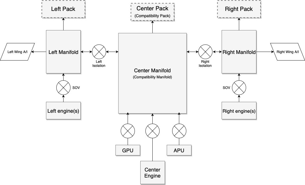
The center components provided for compatibility are clearly marked.
X-Plane legacy aircraft know only one pressurization pack, and one selector that selects the sources for this pack: left hand side of the aircraft, right hand side of the aircraft, and APU. Both APU and the center engine in a one- or three-engined plane are considered to be providing air from the center of the aircraft.
New to X-Plane 11.35 are: GPU bleed, left pack, right pack, wing-anti ice supply, and per-engine shut-off valves.
Another way to understand the system is as a Lancair (legacy X-Plane) overlaid with a King Air overlaid with a 747 – you will then understand how to design many more aircraft types with it:
1. Single-engine plane (Lancair Evolution or similar)
The center pack is the single source of cabin pressure. Packs L and R are always off because they don’t exist.
The bleed selector doesn’t care for left or right or both, the isolation valves have no function, the only available settings are: Bleed “off” meaning engine shut-off valve off and Bleed “on” (any of L, R or BOTH) meaning engine shut-off valve on. Bleed “auto” adds APU valve on (the single engine plane most likely doesn’t have an APU, but if it has, it would work), GPU adds GPU off or on. There’s only one duct, and only one available pressurization pack, center.
2. Two-engine plane with single pressurization (old King Air or similar)
The center duct supplies the one center pack that provides air to the cabin. The pack can be fed from the left engine, the right engine, or both. The bleed air mode thus maps to the isolation valves: left bleed air means left isol valve open, right bleed means right isol valve open, bleed both or auto mean both isolation valves open. If an APU was installed, it would feed into the center duct regardless of the isolation valve settings, controlled by the APU valve, just like the GPU.
3. Four-engine plane (resembling 747)
The system operates exactly like a 747 would: Three packs are available, per-engine SOVs, APU SOV and GPU SOV and two isolation valves work exactly like you’d expect when comparing the above graphic to the schematic of a 747.
4. Twin engine plane (737, A320, CRJ, ERJ, etc.):
Here’s where it gets interesting. For correct operation, one must turn off the legacy center pack and never turn it on again. That must be done actively by script or plugin, since X-Plane will never turn off the center pack – that would break existing aircraft!
The plugin can turn pack C off and pretend it doesn’t exist.
One can then turn on pack L and pack R as per the pack switches.
One can turn off or on the per-engine SOVs as per the engine switches.
Now the only remaining switch is the (single) isolation valve found in such aircraft.
This is where it gets airplane specific and one needs to look at a diagram for the specific airplane: Look up whether the APU and GPU feed into the left or the right from the single isolation valve. For the sake of explanation, let’s assume we are looking at the 737, where the APU feeds into the left duct and GPU feeds into the right duct.
For operation with the APU, the isolation happens to the right of the APU. That is, the isolation valve of the 737 with APU feed is the ISOL R valve in the X-Plane system (and ISOL L is always open). This way, center and left duct belong together, and are fed by left engine and APU. To the right of the isolation valve is the right engine.
For operation on GPU, the isolation happens to the left of the GPU! That is, the isolation valve of the 737 in GPU feed is now the ISOL L valve in the X-Plane system (and ISOL R is always open). This way, the left engine is to the left of the isolation, and GPU and right engine are to the right of the isolation.
Note that GPU and APU can never feed together – in real planes, the APU load control valve is also a one-way check valve. If theAPU valve was commanded to open while the system is pressurized from the GPU, it simply wouldn’t open. In that case, the system operates as GPU-fed until the GPU is off.
5. Twin engine plane (McDonnell-Douglas)
For a plane like the MD-80, which has two isolation valves, operation becomes very simple:
The center pack is turned off (by script or plugin) and never turned on again.
Pack L and pack R are turned on as per the Air Cond Cockpit and Air Cond Shutoff switches.
One can then turn off or on the per-engine SOVs as per the supply switches and fire handles. Both pulling a fire handle or turning off a supply switch should close the engine valve.
The left and right isolation valves separate the side systems with their respective packs from the center duct, into which the APU and GPU feed. These valves are thus direct mappings between X-Plane and and the MD-8x cockpit.
6. Three engined-planes
Because three-engined planes are very dissimilar in design between a 727, DC-10 or Tu-154, X-Plane makes no effort to resemble either – it is expected that custom plugin code will be needed to accurately simulate a three-engine plane.
Electrical power consumption
Having covered the pneumatic side of the system, let’s look at the electric side.
X-Plane has one electrical consumer for “HVAC” that until X-Plane 11.34 could not be controlled via datarefs or commands. From X-Plane 11.35 onwards, the following electrical loads are simulated with the various components of the system:
- AC compressor and fan take 100% of the amp load that is specified
- Fan only takes 10% of the amp load that is specified
- Fan and heater in flight mode take 100% of the amp load that is specified
- Fan and heater in ground mode take 200% of the amp load that is specified
Note that most of this is only relevant to GA planes, not airliners. Airliners do neither have electrical AC compressors nor electric heaters. Heat is supplied by the bleed air alone, it comes out of the engines so hot that it does not need to be heated. The cooling is provided by an air cycle machine driven by bleed air pressure itself, so it does not need lots of electrical power to run the air conditioning to cool it down.
So in an airliner, one would only ever use the fan function, so in Plane Maker, the amp load of the fan times 10 needs to be specified for the whole system, since we are never going to use the remaining 90%.
In a GA plane, the AC compressor is driven by electrical power, so using it will put you in the situation where X-Plane will use 100% of the specified amps.
Some turboprop planes, notably the King Airs and Cheyennes, have not enough heat from the engines to sustain cabin heating alone, so they use an electric heater grid consisting of 8 grids at 36amps each (that is the value for a King Air 90), four of them operate in flight, and an additional four can be activated on the ground when enough power is supplied either by both generators running, or by a GPU. That “ground max” heat setting will double the power consumption, as explained.
Datarefs
sim/cockpit2/pressurization/actuators/air_cond_on int y boolean Electrical air conditioning compressor on, consuming all the amps of rel_HVAC - not needed on airplanes with air cycle machines that drive the air conditioner off the bleed air power itself.
sim/cockpit2/pressurization/actuators/heater_on int y boolean Electrical heater grid on, 0 = off, 1 = flight max (consumes rel_HVAC amps), 2 = ground max (consumes 2x rel_HVAC amps, turned off by weight-off-wheels) - not needed on airplanes that are using hot bleed air and have no heaters
sim/cockpit2/pressurization/actuators/fan_setting int y enum Electric fan (vent blower) setting, consuming 0.1 of rel_HVAVC amps when running. 0 = Auto (Runs whenever air_cond_on or heater_on is on), 1 = Low, 2 = High
sim/cockpit2/bleedair/actuators/engine_bleed_sov int[8] y boolean Engine bleed air shut off valve, close or open
sim/cockpit2/bleedair/actuators/apu_bleed int y boolean APU bleed air valve, close or open. APU must be running at 100%N1 to provide bleed air
sim/cockpit2/bleedair/actuators/gpu_bleed int y boolean GPU bleed air valve, close or open. A GPU is supposed to be always available.
sim/cockpit2/bleedair/actuators/isol_valve_left int y boolean Isolation Valve for left duct, close or open. This separates all engines on the left side of the plane, the left wing, and the left pack from the rest of the system
sim/cockpit2/bleedair/actuators/isol_valve_right int y boolean Isolation Valve for right duct, close or open. This separates all engines on the right side of the plane, the right wing, and the right pack from the rest of the system
sim/cockpit2/bleedair/actuators/pack_left int y boolean Left pressurization pack, off or on. The left pack is supplied from the left side of the plane or through the left isolation valve and only available for airplanes made for 11.35 or newer
sim/cockpit2/bleedair/actuators/pack_center int y boolean Center pressurization pack, off or on. The center pack is supplied from center duct, which can be supplied from a center engine, APU, GPU, or, via the isolation valves, the left and/or right ducts. This pack is the only pack available for airplanes made for X-Plane 11.33 or older
sim/cockpit2/bleedair/actuators/pack_right int y boolean Right pressurization pack, off or on. The right pack is supplied from the right side of the plane or through the right isolation valve and only available for airplanes made for 11.35 or newer
sim/cockpit2/bleedair/indicators/bleed_available_left float n ratio Bleed air available in the left duct, which can come from left engines or through the left isolation valve.
sim/cockpit2/bleedair/indicators/bleed_available_center float n ratio Bleed air available in the center duct, which can come from a center engine, APU, GPU, or, via the isolation valves, the left and/or right ducts.
sim/cockpit2/bleedair/indicators/bleed_available_right float n ratio Bleed air available in the right duct, which can come from right engines or through the right isolation valve.
sim/cockpit2/bleedair/indicators/engine_loss_from_bleed_air_ratio float[8] y ratio Bleed air being sapped from the engine, stealing efficiency from the compressor. Writeable only with override_pressurization set
Commands
sim/bleed_air/engine_1_off
sim/bleed_air/engine_2_off
sim/bleed_air/engine_3_off
sim/bleed_air/engine_4_off
sim/bleed_air/engine_5_off
sim/bleed_air/engine_6_off
sim/bleed_air/engine_7_off
sim/bleed_air/engine_8_off
sim/bleed_air/engine_1_on
sim/bleed_air/engine_2_on
sim/bleed_air/engine_3_on
sim/bleed_air/engine_4_on
sim/bleed_air/engine_5_on
sim/bleed_air/engine_6_on
sim/bleed_air/engine_7_on
sim/bleed_air/engine_8_on
sim/bleed_air/engine_1_toggle
sim/bleed_air/engine_2_toggle
sim/bleed_air/engine_3_toggle
sim/bleed_air/engine_4_toggle
sim/bleed_air/engine_5_toggle
sim/bleed_air/engine_6_toggle
sim/bleed_air/engine_7_toggle
sim/bleed_air/engine_8_toggle
sim/bleed_air/gpu_off
sim/bleed_air/gpu_on
sim/bleed_air/gpu_toggle
sim/bleed_air/apu_off
sim/bleed_air/apu_on
sim/bleed_air/apu_toggle
sim/bleed_air/isolation_left_shut
sim/bleed_air/isolation_left_open
sim/bleed_air/isolation_left_toggle
sim/bleed_air/isolation_right_shut
sim/bleed_air/isolation_right_open
sim/bleed_air/isolation_right_toggle
sim/bleed_air/pack_left_off
sim/bleed_air/pack_left_on
sim/bleed_air/pack_left_toggle
sim/bleed_air/pack_center_off
sim/bleed_air/pack_center_on
sim/bleed_air/pack_center_toggle
sim/bleed_air/pack_right_off
sim/bleed_air/pack_right_on
sim/bleed_air/pack_right_toggle

sim/pressurization/aircond_on
sim/pressurization/aircond_off
sim/pressurization/heater_on
sim/pressurization/heater_grd_max
sim/pressurization/heater_off
sim/pressurization/heater_up
sim/pressurization/heater_dn
sim/pressurization/fan_auto
sim/pressurization/fan_low
sim/pressurization/fan_high
sim/pressurization/fan_up
sim/pressurization/fan_down
Datarefs of the form:
sim/flightmodel2/wing/dataref_name[N]
give you information about the wings – in particular, they tell you the degrees of deflection of the flaps, elevators, etc. etc.
But what number do you use for N ?
The answer is: you pick “N” depending on which airfoil you are animating!
In X-Plane, the horizontal and vertical stabilizers are “wings” too – we call anything that has an airfoil a wing. So you use this table to pick an N that matches what you are doing.
Good:
sim/flightmodel2/wing/aileron1_deg[0] # left aileron
sim/flightmodel2/wing/aileron1_deg[1] # right aileron
sim/flightmodel2/wing/elevator1_deg[8] # left elevator
sim/flightmodel2/wing/elevator1_deg[9] # right elevator
sim/flightmodel2/wing/rudder1_deg[10] # rudder
Usually not good:
sim/flightmodel2/wing/aileron1_deg[8] # aileron on an hstab??
sim/flightmodel2/wing/aileron1_deg[10] # aileron on a rudder?!
sim/flightmodel2/wing/elevator1_deg[0] # elevator on a wing?
sim/flightmodel2/wing/elevator1_deg[10] # elevator on a rudder?
sim/flightmodel2/wing/rudder1_deg[0] # rudder on a wing??
The moral of the story is: pick an array index that matches the part of the plane you are trying to animate!
Unusual Airplanes
The second list is titled “ usually not good” above because there are airplanes with rudders on the wings (think of a flying wing) or V-tails where the tail is half-rudder, half-elevator. The rule still applies: use the index that you are animating! So if you have a rudder on your wing, then use index 0 (left wing 1) for the left wing, etc. The important thing is to pick an array index that matches the Plane Maker part.
Why Is It Like This?
X-Plane is a completely flexible simulator: it lets you put any control surface on any flying surface. If you want to make an experimental design with elevators on the wings, X-Plane is not going to stop you.
In particular, because any flying surface can have any control surface, the datarefs are set up with array indices for all flying surfaces for all control surfaces.
But if your airplane does not have rudders on the wings, the value of those daterfs won’t be useful – they might be ‘correct’, they might be zero, they might be wrong. Don’t trust them! Use the correct array index for the correct wing and your plane will work correctly.
Gyro systems
X-Plane can drive the attitude indicator, also known as the artificial horizon, from any of three systems. This yields a total of six gyros you can use for your attitude instruments (pilot and copilot side). The three systems are:
- vacuum gyro – this one is driven by air being sucked through it, and the vacuum necessary to pull the air into it is generated by an engine-driven vacuum pump. This is the system most often found in simpler general aviation aircraft like a C172. X-Plane simulates a vacuum pump driven off the accessory section of the engine, thus the gyro will spin up when the engine spins up.
Check out the article on the vacuum system itself for more information.
- electric gyro – this gyro replaces the failure-prone vacuum pump, hose, and filter system with a simple electric motor inside the instrument, which spins up the gyro. You find those in non-glass Cirruses, Diamonds, and other more modern general aviation aircraft. X-Plane drives this motor off a DC electric bus, or, if checked in Plane Maker, off the AC inverter.
- AHARS – the fully electronic attitude and heading reference system replaces the gyros with sagnac laser-gyros or cheaper MEMS gyroscopic sensors (comparable to the ones in your smartphone) to generate attitude and heading information without any moving parts. This system is obviously electrically powered.
Limitations of the mechanical attitude gyro instrument
The attitude instrument uses a gimbal mechanism which allows the instrument case (and by extension, the whole airplane) to revolve around the gyro, which keeps pointing upward. The movements of the gimbal are translated by a pickup mechanism into movements of the part of the instrument the pilot is looking at. So while the plane rotates around the gimbal, the deflection of the gimbal is what causes the blue/brown part of the attitude indicator to move. It is important to keep in mind that this pickup mechanism is quite delicate, and also limited in its freedom of movement. It can indicate up to 110 degrees in bank and 70 degrees in pitch. Beyond that, the mechanism locks up and the attitude reading on the instrument becomes inaccurate. Moreover, a violent excursion of the bank or pitch limitations of the instrument can even cause permanent damage to the pickup mechanism, but that doesn’t happen in X-Plane.
After an exceeding of the instrument limitations, the indicated pitch or bank will be off, depending on how far the gyro was forced off from its natural position. The gyro rights itself at three degrees per minute in normal flight conditions, so you will see the attitude indicator correcting itself at this slow rate. To force the gyro back into the upright position quicker, you can pull the caging or fast erect knob.
Caging to the rescue
Aerobatic planes that are expected to exceed 70 degrees of pitch and 110 degrees of bank, if equipped with an attitude indicator at all, will have an instrument that allows caging. A caged gyro is locked to the instrument case, and rather than the delicate pickup mechanism taking the beating, the whole instrument absorbs the gyroscopic forces. While it is caged, the attitude indicator indicates straight and level, while the aerobatic plane can go to extreme bank and pitch angles without damaging the gyro. Back in normal flight, the gyro can be uncaged and resume normal operation.
What is “fast erect”?
On some attitude indicators, the caging knob is instead labeled “(pull to) fast erect”. The mechanism however is the same: When pulled, the gyro is forced into the upright straight and level position and locked to the instrument case, however the fast erect knob snaps back to the uncaged position when let go, while a caging knob can be locked in the caged position. Since they perform the same operation, the knob is the same dataref
sim/cockpit/gyros/gyr_cage_ratio[N]
For a fast erect knob, the dataref can be ramped up with the command
sim/instruments/ah_fast_erect(_copilot)
this simulates pulling out the knob, which instantly springs back when let go.
For the cage knob the command
sim/instruments/ah_cage(_copilot)
instead simulates toggling the knob to the pulled position.
X-Plane has two vacuum systems per airplane, one for the pilot side instruments and one for the copilot side instruments. By default, the suction is generated by pumps driven by the engine, so it is dependent on your engine RPM.
Two additional sources of vacuum are available in X-Plane 11.30:
- an aircraft can be equipped with a venturi tube instead, a very simple system found on vintage aircraft, where the suction is generated by the air going through a venturi tube placed on the fuselage, so it is effected by airspeed and propeller slipstream
- an electric backup pump that can be switched on and provide suction when the engine pumps fail
Engine-driven vacuum pumps – single engine
X-Plane simulates the vacuum system for physical vacuum-driven gyros as follows:
- There are two vacuum systems: One for the pilot instruments, one for the copilot instruments.
- If you have no copilot instruments, then no problem: The second vacuum system goes unused, like it is not even there.
- Each vacuum system has exactly one vacuum pump, which may be failed by the instructor.
- For a single-engine airplane, that one engine turns both pumps… and if your plane has only one system, no problem! Just don’t specify any instruments as “Copilot”, which would have them use the second system.
- The low-vacuum annunciator goes off if EITHER vacuum system runs low, but if you want to make an instrument that tracks WHICH system has run low on pressure, the simply use these datarefs
- For airplanes that have TWO vacuum pumps on ONE system, we just don’t simulate that, just like we don’t simulate both the tire and innertube inside it… we only simulate the actual outgoing force that you see. So, for the dual-vacuum pump planes that have two pumps on one system, simply fail the vacuum pump in the failure list to take out BOTH pumps, since that will remove the pumping pressure from the system.
Engine-driven vacuum pumps – twin engine
- For a multi-engine airplane, engine one turns the pump on system 1, engine 2 turns the pump on system 2… and if your plane has only one system, no problem! Just don’t specify any instruments as “Copilot”, which would have them use the second system.
- If the vacuum system is set up in a way that both engine pumps pull from a common vacuum manifold, check the “vacuum systems cross-tied” in Plane Maker on the Systems page. In this case, with both engines running you will have plenty of suction, and in case of an engine failure, the one remaining pump will be enough to sustain suction at most power settings, but maybe not at idle RPM.
Electric backup
If your aircraft is equipped with an electric backup pump, you can use the dataref
sim/cockpit2/switches/standby_vacuum_pump
to turn on the electric pump in case the engine-driven pump has failed.
Venturi for Vintage aircraft
If you check the “venturi vacuum system” in the Systems page of Plane Maker, X-Plane will not run the engine driven vacuum pumps and instead place a venturi tube on the fuselage, like you’d see in an old a straight-tail 172. That venturi tube will be affected by the airspeed and the propeller slip stream, so you will first see it generating suction during the engine runup, when there is plenty of airflow from the propeller.
Preconditions
To get the correct governor type for a fixed-shaft turboprop, you need to set both the engine type and the failure mode of the prop governor correctly. Then, the prop must be configured for sensible blade angles to achieve correct alpha and beta. Correct behavior of the governor requires correct set up of the prop first. The below guide assumes that:
- you have a “fixed turboprop” type on the engines 2 page.
- you have selected the loss of oil pressure position of the governor to “startlock” on the prop engines spec page.
- you have “constant speed” as the type of the propeller on the props 1 page.
- you have ticked the boxes to allow the prop to go into beta as well as reverse on the engine 1 page.
- you have set up the minimum alpha pitch as fine pitch on the prop 1 page. With the prop at this pitch, it should generate a substantial forward thrust at 0 airspeed.
- you have set up the beta pitch on the engine 1 page. At this pitch, the prop should be generating close to 0 thrust at 0 airspeed.
- you have set up the reverse pitch aft of the beta pitch on the engine 1 page so that the prop can generate negative thrust.
Setting up governed speeds
There’s two governing functions that control the speed of the shaft: The prop governor controls it in alpha mode, and the fuel delivery control controls it in beta mode. The prop governor usually only controls the speed within a range of 96% to 100% of nominal RPM, while the fuel delivery control varies the engine speed between around 60% to 96% of nominal RPM. To set up the governing speeds you need to:
- Provide the nominal (100%) speed in RPM as the “redline engine RPM” speed
- Provide the same 100% speed as the “top of the green arc engine RPM” speed (for correct indication, does not effect governor simulation)
- Provide the minimum alpha speed for the prop governor as the “bottom of green arc engine RPM” – this is usually 96% of the nominal RPM. This value will be used as the lowest selectable for the prop governor in alpha mode and also for the underspeed governor that will increase fuel flow to keep the RPM up in alpha mode.
- Provide the lower limit for beta operation (65-73% of nominal RPM on most installations) as “minimum governor speed engine RPM”. This is the minimum RPM achievable in beta with the prop speed lever as far back as to not cross over into feather. This is the lowest RPM that can be set with fuel delivery control.
Setting up the engine idle fuel adjustments
Fuel delivery control works by manipulating the “idle_speed_ratio” actuator, so it changes the idle speed between “low_idle_ratio” and “high_idle_ratio” to govern the engine speed in beta mode. In order to do so effectively, you must tweak the low and high idle to be suitable for the governor. To do so, start up X-Plane and run these two tests:
- Place the power lever just below flight idle, in the tiniest bit of beta you can get. Basically, toggle into beta mode and then advance to beta_ref=0.01 or just the tiniest bit of beta. This way, the prop will be at or very close to the minimum alpha angle, thus grabbing the highest load it can get without crossing over into alpha fully. With the engine speed lever fully forward, the fuel delivery control must now achieve bottom of green arc RPM – usually around 96%. It will do so by running up the “idle speed ratio” towards high idle. Now tweak the “high idle ratio” parameter such that the governor sets an idle speed ratio close to 1.0. In other words, we want the fuel delivery control to be using close to all of its idle fuel here. The engine should be operating very close to the maximum idle ratio. Note the “high_idle_ratio” dataref now.
- Place the power lever as far back into beta without getting reverse thrust. With a properly set up prop, that means beta_ref=1.0. The prop is now at full beta pitch and should be producing very little thrust now and provide the lowest load on the engine. Observe that fuel delivery control will have lowered the idle speed ratio somewhat because it doesn’t need as much fuel flow now to keep the engine turning at min green RPM. Now pull the speed lever back as far as it goes without going into feather. You should be at about 2% travel on the prop axis to achieve minimum RPM short of feather. This will cause the fuel delivery control to call for a very low idle speed ratio to get the RPM down to the minimum governed RPM now, which will typically be between 65-73%. Now, tweak the “low idle ratio” so that the governor will use about 0.3 of “idle speed ratio” to achieve this lowest governed RPM (we need about 30% room below for the engine to spool down). Write down that “low idle ratio” dataref now.
Now back in Plane Maker, on the engines 1 page, set the parameters “hi idle fuel adjustment” and “low idle fuel adjustment” to the two values obtained.
Only with the idle parameters set sensibly, you will get proper response going in and out of beta mode, i.e. when going from flight to ground idle.
Finally, you probably will find that the “throttle available at max reverse lever position” should be low. During reverse, as the prop moves from beta pitch towards reverse pitch, it picks up more load, and this is counteracted by fuel delivery control, keeping engine speed up at the bottom of the green arc. Only if you find that at your reverse pitch you need additional throttle (more than fuel delivery control will provide) to keep the RPM up, should you allow for more throttle here.
X-Plane 11.30 offers to equip planes with preconfigured autopilots, in addition to the many configurable options of previous X-Plane versions. Some of the available autopilots come with additional features.
Read More
The X-Plane autopilot works with cascaded PID controllers. Tuning the PID controllers for your aircraft is key to having a smooth working autopilot. This article explains the parameters you can set in Plane Maker, and how to tweak them.
Read More