X-Plane features datarefs that let you override parts of the flightmodel. While these datarefs are often named for the dataref whose value you control when the override is enabled, they really act by removing logic blocks from X-Plane’s flight model and systems simulation. This article explains the exact effects of overriding the prop_pitch and prop_mode overrides.
Prop Modes In X-Plane for Constant RPM Props.
X-Plane’s prop model features four prop modes for constant-RPM props in sim/flightmodel2/engine/actuators/prop_mode:
- Feathered (prop_mode = 0): the prop goes to its feathered pitch as set in the .acf file.
- Alpha range (prop_mode = 1): this is normal operation – a target RPM is set with the blue prop levers. This is visible via sim/cockpit2/engine/actuators/prop_rotation_speed_rad_sec. The governor tries to adjust pitch within the range of the min and max pitch as set in Plane-Maker to maintain commanded RPM if possible.
- Beta range (prop_mode = 2): prop pitch is commanded directly with the throttle as it moves through the beta range – the engine is at idle and the prop angle changes. On some planes the prop may even go into a reverse range while in beta mode – this is set in Plane-Maker.
- Reverse range (prop_mode = 3): prop pitch is commanded directly with the throttle and goes from the beta pitch to reverse pitch, and throttle commands the actual throttle. This can be used to simulate reverse-by-throttle or a range of reverse angles or both.
X-Plane will set the prop target speed with the prop joystick axis if assigned, and the throttle with the throttle axis if assigned. The prop mode is set between reverse/beta/alpha by commands, and feathering happens via a series of on-board systems, e.g. feather when mixture is pulled, auto-feather, or feather when the prop lever is pulled past a detent.
Overriding prop_mode
When sim/operation/override/override_prop_mode is set to 1, X-Plane will not move the prop mode between alpha, beta and reverse when (1) the panel 2-d throttles are dragged or (2) a joystick axis moves into a new range on an aircraft with beta and reverse ranges built into the throttle. (This is a .acf setting.)
X-Plane will change modes if you write to the dataref or when commands like sim/engines/thrust_reverse_toggle and sim/engines/beta_toggle are run; to ensure complete control of the dataref, override commands that affect beta or reverse.
When prop_mode is overridden and prop_pitch is not overridden, X-Plane will control feathering automatically, and writes of 0 to the prop_mode will be rejected. Automatic feathering in the sim will still work.
Overriding prop_pitch
When setting sim/operation/override/override_prop_pitch to 1, X-Plane will not change the prop pitch. A bunch of code is bypassed:
- The joystick prop axis will not set the prop pitch (for variable pitch props) and will not set the target RPM (for constant RPM props). You must read the axis yourself using sim/joystick/joy_mapped_axis_avail and sim/joystick/joy_mapped_axis_value – array index 8 for a single global prop lever or 24-27 for individual prop levers.
- Constant mach and thrust-vectored props will not auto-adjust the target RPM.
- Feathering is disabled; you must set the prop mode to feather, and you must set the actual prop angle. Setting a prop mode of 0 and not setting the angle will not result in feathering!
- Constant RPM props will not set their pitch.
You can set the prop angle directly via sim/cockpit2/engine/actuators/prop_angle_degrees.
Setting up idle speed is a four-step process:
- Setting the minimum “smooth” running speed.
- Getting the internal friction right.
- Setting the right amount of throttle to overcome the internal friction.
- Setting the fuel flow for that idle throttle
The “minimum engine running speed” setting in Plane Maker does NOT set the idle speed itself, but the minimum engine RPM that results in a smooth operation. This speed is lower than what we want the engine to actually idle at. If the RPM falls below the minimum running speed we will experience “stumbling” that manifests in RPM and torque fluctuations. If RPM drops far enough below that minimum speed, combustion itself will be affected and unable to sustain engine operation at all. The engine will come to a halt. The strength of the stumbling effect at lower-than-minimum RPM is determined by the number of cylinders that is set in Plane Maker. A four cylinder engine will exhibit more stumbling than a 6 cylinder engine or a radial engine with even more cylinders.
For a typical flat-four engine, the target idle will be around 600-700 RPM, while the minimum running RPM should be set closer to 500. This provides a good margin to keep the engine running under load from the alternator and at higher altitudes and hotter days where the engine makes less power. If the RPM drops below that setting of 500, expect erratic engine behavior.
The idle throttle setting serves one purpose, and that is overcoming the engine’s internal friction. The idle speed of the engine is determined by the equilibrium of the torque produced by the engine at idle throttle setting and the torque consumed by the engine at idle. That torque that needs to be overcome is the engine’s own internal friction, plus the small torque consumed by the propeller rotating at slow speed, plus any additional loads from the generator the engine needs to turn.
The engine’s internal friction is controlled in Plane Maker with the “engine friction” ratio. X-Plane’s guess at 1.0 works for a big-bore high compression direct-drive engine such as the IO-550 found on a Cirrus or Columbia. Other engines with different compression ratios or gearing will likely require different values here.
A good way to find the right internal friction, if the propeller is set up correctly, is to turn the engine off in flight (by cutting the mixture) and slowing the aircraft down to just above stall speed. The engine should almost stop turning as the airplane approaches stall speed, but rotate practically unaffected at greater air speeds (note that once fully stopped, a disproportionately high airspeed is needed to get the prop turning again).
The suggested process is to tune the sim/aircraft2/engine/engine_friction_ratio dataref in the simulator, take note of the value that produces the desired result, and then set it to the acf permanently in Plane Maker.
Once the internal friction is set, the airplane should be placed at a sea-level airport in standard atmosphere (15C OAT, 1013hPA QNH) and the electrical system loaded up with all electrical loads that are reasonably expected to be on on the ground ready for take-off, that is avionics bus powered, navigation and landing lights on, etc.
Then the idle throttle adjustment (sim/aircraft2/engine/high_idle_ratio) should be made so that the engine runs at a minimum smooth idle RPM with the throttle all the way out.
This will likely be too low to run the generator or alternator enough to charge the battery. That is not a bug, but corresponds to behavior found on many real piston aircraft. Basically all real piston engines require a positive throttle input to run at a high enough RPM to sustain generator load to charge the battery along with other electrical loads.
It is important to let the engine run for a minute or longer, as it might take some time to find the equilibrium between drive torque (generated by the engine) and drag torque (consumed by the engine itself, the propeller, and the generator).
The idle should be tweaked in the simulator with the sim/aircraft2/engine/high_idle_ratio dataref, and the desired value then set permanently in Plane Maker.
Once the engine runs stable at a low RPM in this config, it is up to the user (i.e. pilot, not aircraft developer) to run the throttle up enough to sustain battery charging.
Finally, the desired fuel flow at this setting can be adjusted with the dataref sim/aircraft/overflow/ff_rat_idle_PRP in the simulator and permanently saved to the acf in Plane Maker on the SFC (specific fuel consumption) tab.
Note that setting the engine up like this corresponds to a sea-level setup as would be performed on most aircraft.
Taking this aircraft to a high elevation airport such as Leadville, CO, will result in the engine stumbling or maybe even stopping at idle in a very short period of time. That is not a bug, but corresponds to how a real aircraft would behave at high density altitudes. It is absolutely necessary to lean the mixture and increase the throttle to sustain a good idle at high density altitudes, both in the real world and in X-Plane. In practice, the pilot will add throttle to keep the engine running, then slowly pull out the mixture control and watch the tachometer, to lean the engine to peak RPM, then reduce the throttle again to the desired RPM as dictated by electrical needs.
X-Plane has three hydraulic systems per aircraft that can power a variety of actuators. Most notably, each flight control surface can be powered by any combination of hydraulic actuators.
Hydraulic power sources
Each of the three hydraulic systems can be pressurized from
- an engine-driven pump
- a rotor-driven pump (so helicopters with free-wheeling transmissions can retain hydraulic power in auto-rotation)
- an electrically operated pump
- a ram-air driven turbine (RAT)
- a bleed-air driven pump
By default, engine- and rotor-driven pumps operate continuously, but they can be unloaded with the datarefs
sim/cockpit2/hydraulics/actuators/engine_pump int[8] y boolean and
sim/cockpit2/hydraulics/actuators/prop_pump int[8] y boolean respectively.
Note that these datarefs do nothing if the pump hasn’t been assigned to provide pressure to any system in Plane Maker.
The electric pumps are switched with the datarefs
sim/cockpit2/hydraulics/actuators/electric_hydraulic_pump_on int y boolean
sim/cockpit2/hydraulics/actuators/electric_hydraulic_pump2_on int y boolean
Again, switching them on does nothing unless the pump has been assigned a hydraulic system in Plane Maker.
If assigned in Plane Maker, the pumps will consume the assigned amps from their electrical busses, and can be failed with their failure datarefs
sim/operation/failures/rel_hydpmp_ele and /rel_hydpmp_el2
The RAT (ram-air turbine) automatically activates if it has been assigned in Plane Maker, and the airplane is off the ground (weight-off-wheels) and all other hydraulic sources have failed and some time has passed for pressure to bleed from the system. Alternatively, the RAT can also be controlled manually with the dataref
sim/cockpit2/hydraulics/actuators/ram_air_turbine_on int y boolean
Hydraulic PTU
The power transfer unit can be installed with Plane Maker to allow power transfer between system 1 (left) and system 2 (right). The PTU can either be uni-directional, allowing power transfer only in the specified direction, or bi-directional, in which case it will keep the weaker system powered by the stronger system, as long as the weaker system has enough hydraulic fluid left. Note that the PTU only transfers power, but no fluid is transferred between systems.
When installed in the plane, the PTU has three possible states during flight:
sim/cockpit2/hydraulics/actuators/PTU int y enum
- PTU is off, and no power transfer takes place.
- PTU is armed and watching for pressure differential
- PTU is running currently, trying to equalize pressure. When pressure differential is minimized, it will fall back to state 1
In auto mode, which is the default, the PTU is watching for a pressure differential and will turn on and off as needed to keep it minimal. This causes the characteristic on-off-cycle that on some airplanes can be heard as a “barking dog” sound. This is a purely mechanical operation, no electric power or sensors are needed for this to work.
Hydraulic actuators (power consumers)
Each of these can be assigned on or more hydraulic actuators, so they can be powered from one or multiple systems:
- nosewheel steering
- flaps
- slats
- landing gear (see the article on hydraulic landing gear actuators for more detail)
- wheel brakes (through an accumulator that will store pressure for a few brake applications)
- thrust reversers
Each of these will not be able to operate without hydraulic pressure from at least one selected source, or operate at reduced deflection, speed, or efficacy at low pressures.
Notice the primary flight controls are missing from this list – they have moved to the the flight control configuration in Plane Maker, Control Geometry, Hydraulic tab.
Hydraulic flight control actuators
The following primary and secondary flight controls can be assigned to hydraulic systems on a per-wing basis:
- aileron group 1
- aileron group 2
- elevator 1
- elevator 2
- rudder 1
- rudder 2
- spoiler group 1
- spoiler group 2
- speed brake group 1
- speed brake group 2
- yawbrake
Each of these actuators can be assigned any combination of hydraulic systems. Each of these assignments can be made separately for any of these wings:
- wing 1-4 left and right
- left and right horizontal stabilizer
- vertical stabilizers 1 and 2
Note that Plane Maker will only display the options for wings the plane actually has, and only when an element of the wing is selected to have that type of control. This keeps the table simple for most airplanes.
That makes it possible to create complex assignments of individual spoiler tabs that will stop operating when pressure is lost from the specified system.
X-Plane previous to version 12 treated all flying surfaces (wing, tail, horizontal and vertical stabilizer) as one when it came to ice accumulation and anti- or de-ice measures. Newer versions treat the tail surfaces different from the wing surfaces.
Tail surface ice datarefs
Now the wing surfaces are separate from the tail surfaces. Each tail and wing surface can accumulate ice separately. The new datarefs for ice on the tail are
sim/flightmodel/failures/tail_ice    float    y    ratio    Ratio of icing on tailplane (hstab and vstab) - left side

sim/flightmodel/failures/tail_ice2    float    y    ratio    Ratio of icing on tailplane (hstab and vstab) - right side
The new dataref that decides what to do with the tail is:
sim/cockpit2/ice/ice_tailplane_man int y enum De-ice tailplane automatically with wing/airframe deice, or separately with new datarefs. 0 = Auto, Default: Tail is deiced with whatever acts on the wings. 1 = Man: Tailplane de-ice is no longer slaved and must be turned on with separate datarefs.
Legacy aircraft use the “0” default setting, so all surface de-ice will automatically de-ice the tail as well, to preserve behavior from previous versions that did not distinguish between wing and tail surfaces.
Tail anti- and de-ice
For the tail, you now have the set of datarefs for the same options as for the wings:
sim/cockpit2/ice/ice_tail_heat_left_on int y boolean De-ice switch, 0 or 1. Anto-ice – electric heat. This switch engages electrically heated leading edges. (Left tailplanes)
sim/cockpit2/ice/ice_tail_heat_right_on int y boolean De-ice switch, 0 or 1. Anti-ice – electric heat. This switch engages electrically heated leading edges. (Right tailplanes)
sim/cockpit2/ice/ice_tail_boot_on int y enum De-ice switch, 0, 1, 2, 3. De-ice – pneumatic. This switch inflates flexible bladders on the wing leading edges to pop off accumulated ice. 0 = Off, 1 = Continuous, 2 = Single/Auto (deflates automatically), 3 = Man (deflates when switch let go) (All tailplanes)
sim/cockpit2/ice/ice_tail_boot_left_on int y enum De-ice switch, 0, 1, 2, 3. De-ice – pneumatic. This switch inflates flexible bladders on the wing leading edges to pop off accumulated ice. 0 = Off, 1 = Continuous, 2 = Single/Auto (deflates automatically), 3 = Man (deflates when switch let go) (Left tailplanes)
sim/cockpit2/ice/ice_tail_boot_right_on int y enum De-ice switch, 0, 1, 2, 3. De-ice – pneumatic. This switch inflates flexible bladders on the wing leading edges to pop off accumulated ice. 0 = Off, 1 = Continuous, 2 = Single/Auto (deflates automatically), 3 = Man (deflates when switch let go) (Right tailplanes)
sim/cockpit2/ice/ice_tail_hot_bleed_air_on int y boolean De-ice switch, 0 or 1. Anti-ice – bleed air. This switch directs warm air from the engines into the tailplane leading edges to keep them free of ice. (All tailplanes)
sim/cockpit2/ice/ice_tail_hot_bleed_air_left_on int y boolean De-ice switch, 0 or 1. Anti-ice – bleed air. This switch directs warm air from the engines into the tailplane leading edges to keep them free of ice. (Left tailplanes)
sim/cockpit2/ice/ice_tail_hot_bleed_air_right_on int y boolean De-ice switch, 0 or 1. Anti-ice – bleed air. This switch directs warm air from the engines into the tailplane leading edges to keep them free of ice. (Right tailplanes)
sim/cockpit2/ice/ice_tail_tks_on int y enum De-ice switch, 0, 1, or 2. Anti-ice – TKS fluid. This switch activates the pump for the weeping wing, dissipating TKS fluid on the leading edges to keep them free of ice. 0 = Off, 1 = Norm, 2 = High. (All tailplanes)
sim/cockpit2/ice/ice_tail_tks_left_on int y enum De-ice switch, 0, 1, or 2. Anti-ice – TKS fluid. This switch activates the pump for the weeping wing, dissipating TKS fluid on the leading edges to keep them free of ice. 0 = Off, 1 = Norm, 2 = High. (Left tailplanes)
sim/cockpit2/ice/ice_tail_tks_right_on int y enum De-ice switch, 0, 1, or 2. Anti-ice – TKS fluid. This switch activates the pump for the weeping wing, dissipating TKS fluid on the leading edges to keep them free of ice. 0 = Off, 1 = Norm, 2 = High. (Right tailplanes)
By default ( ice_tailplane_man == 0) all these are slaved to the wing counterparts – so if you switch anything on the wing on, the tail counterpart will go on, to preserve the old behavior. Also, the bleed air, TKS fluid, etc usage is tweaked so that it stays unchanged if both tail and wing are switched on (i.e. with both tail and wing on resource use equals former use of wing only).
If you chose to set the tailplane to manual (1) you can use all the new datarefs independently.
Pneumatic De-icing boots operation and animation
For the boots themselves: Two new datarefs exist for the inflation – these could be used to animate actual boots:
sim/cockpit2/ice/ice_wing_boots_inflation    float[2]    y    ratio    De-icing boots inflation ratio, left and right wing

sim/cockpit2/ice/ice_tail_boots_inflation    float[2]    y    ratio    De-icing boots inflation ratio, left and right tailplane
The boots take 6 seconds to inflate fully, and about three to be sucked empty again by vacuum. Note that the de-ice failure affects inflation, while lack of vacuum effects deflation.
Each boot switch dataref now has four settings:
0 = Off
1 = Continuous – this is to provide compatibility with 11.30. The boots are repeatedly cycled in auto mode whenever ice up to 0.2 has accumulated.
2 = Auto/Single – this initiates a six second inflation followed by a 3 second deflation regardless whether switch is sprung back or held in position.
3 = Man – this initiates an inflation and keeps the boots inflated for as long as the switch is held. Upon switching back to 0, deflation happens with vacuum.
The following commands are new to satisfy the new switch positions and act as if the switch is spring-loaded (the existing commands work for 0/Off and 1/Continuous for compatibility):
"sim/ice/wing_boot_single"                 ,"Anti-ice: all wing, de-icing boots single auto."

"sim/ice/wing_boot0_single"                ,"Anti-ice: left wing, de-icing boots single auto."

"sim/ice/wing_boot1_single"                ,"Anti-ice: right wing, de-icing boots single auto."
"sim/ice/wing_boot_man" ,"Anti-ice: all wing, de-icing boots manual."

"sim/ice/wing_boot0_man" ,"Anti-ice: left wing, de-icing boots manual."

"sim/ice/wing_boot1_man" ,"Anti-ice: right wing, de-icing boots manual."
All commands now have counterparts for tail:
"sim/ice/tail_heat_on" ,"Anti-ice: all tail, anti-ice heat on."

"sim/ice/tail_heat0_on" ,"Anti-ice: left tail, anti-ice heat on."

"sim/ice/tail_heat1_on" ,"Anti-ice: right tail, anti-ice heat on."
"sim/ice/tail_heat_off" ,"Anti-ice: all tail, anti-ice heat off."

"sim/ice/tail_heat0_off" ,"Anti-ice: left tail, anti-ice heat off."

"sim/ice/tail_heat1_off" ,"Anti-ice: right tail, anti-ice heat off."
"sim/ice/tail_heat_tog" ,"Anti-ice: all tail, anti-ice heat toggle."

"sim/ice/tail_heat0_tog" ,"Anti-ice: left tail, anti-ice heat toggle."

"sim/ice/tail_heat1_tog" ,"Anti-ice: right tail, anti-ice heat toggle."

"sim/ice/tail_boot_on" ,"Anti-ice: all tail, de-icing boots on schedule."

"sim/ice/tail_boot0_on" ,"Anti-ice: left tail, de-icing boots on schedule."

"sim/ice/tail_boot1_on" ,"Anti-ice: right tail, de-icing boots on schedule."
"sim/ice/tail_boot_off" ,"Anti-ice: all tail, de-icing boots off."

"sim/ice/tail_boot0_off" ,"Anti-ice: left tail, de-icing boots off."

"sim/ice/tail_boot1_off" ,"Anti-ice: right tail, de-icing boots off."
"sim/ice/tail_boot_tog" ,"Anti-ice: all tail, de-icing boots toggle."

"sim/ice/tail_boot0_tog" ,"Anti-ice: left tail, de-icing boots toggle."

"sim/ice/tail_boot1_tog" ,"Anti-ice: right tail, de-icing boots toggle."
"sim/ice/tail_boot_single" ,"Anti-ice: all tail, de-icing boots single auto.",

"sim/ice/tail_boot0_single" ,"Anti-ice: left tail, de-icing boots single auto."

"sim/ice/tail_boot1_single" ,"Anti-ice: right tail, de-icing boots single auto."
"sim/ice/tail_boot_man" ,"Anti-ice: all tail, de-icing boots manual.",

"sim/ice/tail_boot0_man" ,"Anti-ice: left tail, de-icing boots manual."

"sim/ice/tail_boot1_man" ,"Anti-ice: right tail, de-icing boots manual."

"sim/ice/tail_tai_on" ,"Anti-ice: all tail, bleed anti-ice on."

"sim/ice/tail_tai0_on" ,"Anti-ice: left tail, bleed anti-ice on."

"sim/ice/tail_tai1_on" ,"Anti-ice: right tail, bleed anti-ice on."
"sim/ice/tail_tai_off" ,"Anti-ice: all tail, bleed anti-ice off."

"sim/ice/tail_tai0_off" ,"Anti-ice: left tail, bleed anti-ice off."

"sim/ice/tail_tai1_off" ,"Anti-ice: right tail, bleed anti-ice off."
"sim/ice/tail_tai_tog" ,"Anti-ice: all tail, bleed anti-ice toggle."

"sim/ice/tail_tai0_tog" ,"Anti-ice: left tail, bleed anti-ice toggle."

"sim/ice/tail_tai1_tog" ,"Anti-ice: right tail, bleed anti-ice toggle."

"sim/ice/tail_tks_on" ,"Anti-ice: all tail, TKS de-ice normal."

"sim/ice/tail_tks0_on" ,"Anti-ice: left tail, TKS de-ice normal."

"sim/ice/tail_tks1_on" ,"Anti-ice: right tail, TKS de-ice normal."
"sim/ice/tail_tks_high" ,"Anti-ice: all tail, TKS de-ice high."

"sim/ice/tail_tks0_high" ,"Anti-ice: left tail, TKS de-ice high."

"sim/ice/tail_tks1_high" ,"Anti-ice: right tail, TKS de-ice high."
"sim/ice/tail_tks_off" ,"Anti-ice: all tail, TKS de-ice off."

"sim/ice/tail_tks0_off" ,"Anti-ice: left tail, TKS de-ice off."

"sim/ice/tail_tks1_off" ,"Anti-ice: right tail, TKS de-ice off."
"sim/ice/tail_tks_tog" ,"Anti-ice: all tail, TKS de-ice toggle."

"sim/ice/tail_tks0_tog" ,"Anti-ice: left tail, TKS de-ice toggle."

"sim/ice/tail_tks1_tog" ,"Anti-ice: right tail, TKS de-ice toggle."
X-Plane provides two ways to trim the elevator or stabilizer of a plane: Mechanical or with an electric servo. The presence of an electric servo has consequences to the type of commands you can use the move the trim, and the commands you want to set up for hardware. This article explains the interaction of the commands and X-Plane systems code.
Trim commands for pilots – how to configure your flight control hardware
X-Plane provides separate commands for electric and mechanical trim, and a catch-all command for trim that would work with either system. Most of the time, you’d want your flight control yoke or joystick to trigger the generic command, so you can fly with any type of aircraft:
sim/flight_controls/pitch_trim_up

sim/flight_controls/pitch_trim_down
will dispatch the command to an electric trim servo, if the plane has one, and to moving the trim wheel, if that’s the only way of trimming the plane has.
If you have a more advanced setup involving more hardware, you can easily configure your yoke trim rocker to actuate the electric commands, while a switch on your throttle console acts on the mechanical commands. This way, you can realistically deal with a servo failure in a plane that has one: As long as the servo is on, you trim with your thumb on your yoke, and if the servo is off, you can still “grab the wheel” on your console to move the trim. This obviously also works if you have an actual hardware wheel which you assign to an axis instead of a button. The respective commands are:
sim/flight_controls/pitch_trim_up_elec

sim/flight_controls/pitch_trim_down_elec

sim/flight_controls/pitch_trim_up_mech

sim/flight_controls/pitch_trim_down_mech
an even more advanced yoke might also have split trim switches where both channels need to be active in order to trim. Commands for this are:
sim/flight_controls/pitch_trimA_up

sim/flight_controls/pitch_trimA_down

sim/flight_controls/pitch_trimB_up

sim/flight_controls/pitch_trimB_down
Another important difference is that electric trim by pilot action will necessarily trim-interrupt and disconnect the autopilot, while displacing the mechanical trim wheel (by command or by axis) will not!
Trim commands for airplane creators
A legacy aircraft will detect the type of trim system based on the presence of an autopilot: A plane with a single-axis autopilot is assumed to have no electric trim servo. A plane equipped with a dual-axis or better autopilot is assumed to have an electric trim servo and use it as primary means of trim.
New aircraft can specify the trim servo with the option “electric trim servo equipped” in Plane Maker on the trim controls page.
When you have an electric trim servo it can be switched on or off with the dataref
sim/cockpit2/autopilot/electric_trim_on
switching it off will not only prevent the autopilot from using it, but also cause electric trim commands to no longer work. The same thing happens when the “Elevator trim actuator” failure is triggered – the servo will fail and you can only trim mechanically.
If your plane does not have an electric servo (by means of not having selected one, or by being a legacy plane with a single-axis auto-pilot), assigning any bus or amperage to the trim actuator does nothing. The failure of the trim actuator then refers to a jamming of the mechanism, rather than a servo failure.
Make sure to assign the “Elevator trim actuator” a bus and an amperage in Plane Maker, so it only runs when the correct electrical system is powered.
When it comes to the 3D cockpit, assign the manipulator of the physical wheel to either the _mech commands, or to the trim dataref. Assign the _elec commands to rocker switches. Since you know which system your specific aircraft has, you should never need to assign the catch-all commands to anything in your 3D cockpit.
X-Plane historically had only one windshield for the 2d cockpit, on which effects for icing, rain or wipers were displayed. With the advent of more sophisticated 3d effects, it has become necessary to simulate more than one glass surface for looking out.
Index conventions
X-Plane 12 has four distinct window surfaces. They are numbered as follows:
- Pilot front windshield
- Copilot front windshield
- Pilot side window
- Copilot side window
Even numbers refer to the left side (0 being even) and odd numbers to the right side.
Ice and defrost
Depending on temperature and weather conditions around the airplane, ice can form on the windows. The amount of ice is tracked as a ratio from 0..1 and available as an array dataref, index as per above
sim/flightmodel/failures/window_ice_per_window float[4]
The pilot can turn on electric heating for each window (a real airplane might not have heat for every window, in which case there simply wouldn’t be switches for some of the dataref indices).
sim/cockpit2/ice/ice_window_heat_on_window int[4]
controls the electric switches, which will then consume the amps set in Plane Maker for
De-ice: window heat, De-ice: window heat copilot, De-ice: l side window heat and De-ice: r side window heat respectively.
The heating elements can be failed by their respective bus, or the failure datarefs
sim/operation/failures/rel_ice_window_heat

sim/operation/failures/rel_ice_window_heat_cop

sim/operation/failures/rel_ice_window_heat_l_side

sim/operation/failures/rel_ice_window_heat_r_side
Wipers
X-Plane has two wiper speed controllers, acting on the left (even numbered) wipers and right (odd numbered wipers).
sim/cockpit2/switches/wiper_speed_switch int[2] y enum 0=park, 1=25%speed,2=50%speed,3=100%speed
Wiper speed 0 is aliased to the old wiper_speed dataref for backward compatibility for the pilot windshield.
Four wipers can be defined in Plane Maker and assigned min and max deflection angles. If your aircraft has less than four wipers, simply assign the unnecessary wipers so that angle 1 == angle 2, in which case no movement will be generated.
At runtime,
sim/flightmodel2/misc/wiper_angle_deg float[4] n degrees
tells you the deflection of each wiper and this dataref will be used to wipe the 3d rain off the windshield in the 3d cockpit as well.
Rain repellent
Some business jets don’t have wipers, and instead rely on airflow alone to run the water off of specially coated windshields.
On the ground, a blower is used to generate an airflow over the windshield, to run off water when airspeed is insufficient to do so. In X-Plane, you can turn on two blowers for left and right side with the dataref
sim/cockpit2/switches/rain_repellent_switch int[2] y boolean
This will use electric power to generate the airflow.
In many jet aircraft with conventional flight controls, the pilot and copilot-side primary flight controls are linked by torque tubes. This normally ensures both control columns move in unison in pitch and roll, and all ailerons, roll spoilers and elevators are actuated in a coordinated manner.
In case of a flight control malfunction were a jam occurs in one system, it is usually possible to split the controls, in some aircraft by pulling a flight control disconnect handle, in others the torque tube shears when a certain (high) load is applied to it.
X-Plane simulates both the type of failure and the flight control split to deal with it.
Control-jamming failures
Each of the primary controls can be jammed on either side, using the failure, or the failure datarefs:
sim/operation/failures/rel_ail_L_jam int y failure_enum roll control, left control column jammed

sim/operation/failures/rel_ail_R_jam int y failure_enum roll control, right control column jammed

sim/operation/failures/rel_elv_L_jam int y failure_enum pitch control, left control column jammed

sim/operation/failures/rel_elv_R_jam int y failure_enum pitch control, right control column jammed
Jamming either side will block the respective axis at its current deflection and prevent further movement until the controls are split.
Splitting and regaining control
On some airplanes, pitch and roll can be split separately, on others, the split affects both but they can be reconnected individually. X-Plane can simulate all of these situations by means of these datarefs:
sim/cockpit2/controls/torque_tube_split_roll int y boolean0 = Normal: Left and right roll input are connected, 1 = Disconnected, each joystick roll input for pilot or copilot goes to the respective side.
sim/cockpit2/controls/torque_tube_split_pitch int y enum 0 = Normal: Left and right pitch input are connected, 1 = Disconnected, each joystick pitch input for pilot or copilot goes to the respective side.
On some airplanes, these datarefs will only ever work in unison, while other airplanes might have separate handles to pull and therefore the datarefs can have individual values.
When the flight controls are split, the user’s joystick or yoke input will act on the pilot’s side only, and if a joystick input is configured for the copilot’s side, it will go the copilot’s side only.
For home use setups with only one set of flight control hardware, it is however possible to route the user input over to the copilot’s side by pressing and holding the priority button (normally the same command as the autopilot servo disconnect). By holding the priority button for 40 seconds, the user can effectively switch into the copilot’s seat and fly the copilot flight controls from the only connected joystick.
Roll spoiler actuation
A roll spoiler is a spoiler tab that goes up on the side the aileron goes up. Typically, it is linked to the on-side aileron only. That is, for a right turn, the right roll spoiler goes up as the right aileron deflects up. In case of a control split, initially only the spoiler on the side of the working aileron will be actuated, while the one on the side of the jammed aileron will not get a signal to operate, even though the spoiler control itself is not failed. In this case, the side with the working roll input can be chosen to actuate both sides of roll spoilers:
sim/cockpit2/controls/roll_spoiler_actuation int y enum 0 = Normal: left roll spoiler is controlled by left roll input, right roll spoiler is controlled by right roll input. 1 = Left: Both roll spoilers are controlled by the left aileron. 2 = Right: Both roll spoilers are controlled by the right aileron.
Operational example
Assume a jamming occurs somewhere in the right aileron control cables: sim/operation/failures/rel_ail_R_jam == 6
Now, the roll control is jammed and the ailerons cannot be moved.
The pilot pulls the flight control disconnect for the roll axis: sim/cockpit2/controls/torque_tube_split_roll = 1
Now, the pilot’s roll input acts on the left aileron only. Since the left aileron is not jammed, it will now deflect up or down responding to control input, and allow limited maneuvering while the right aileron remains locked in its jammed position.
In this situation left roll spoiler will work, the right won’t. Some airplanes allow the right roll spoiler operation to be restored by selecting sim/cockpit2/controls/roll_spoiler_actuation = 1
For aircraft designers
First, aircraft designers must tell X-Plane whether the cockpit flight controls are linked (most small aircraft, Boeing aircraft, older non-FBW Airbus aircraft) or are electronically added (new Airbus and other FBW aircraft with stick input). To animate the cockpit controls correctly the following datarefs should be used:
- For linked (“Boeing”) flight controls, the pilot side yoke/stick should be animated with
sim/cockpit2/controls/total_pitch_ratio and sim/cockpit2/controls/total_roll_ratio. The co-pilot side yoke/stick should use sim/cockpit2/controls/total_pitch_ratio_copilot and sim/cockpit2/controls/total_roll_ratio_copilot. X-Plane will ensure the controls move together based on flight control linkage, and with autopilot input.
- For independent (“Airbus”) flight controls, the pilot side stick should be animated with
sim/cockpit2/controls/yoke_pitch_ratio and sim/cockpit2/controls/yoke_roll_ratio. The co-pilot side stick should be animated using sim/cockpit2/controls/yoke_pitch_ratio_copilot and sim/cockpit2/controls/yoke_roll_ratio_copilot. X-Plane will ensure the control inputs are added or filtered as needed and also not deflect the sticks with the autopilot. See below for commands for the priority pushbuttons.
For animating the flight control surfaces on the wings and tail, it is imperative that the correct animation datarefs are used on each wing, and not simply animations mirrored between right and left or keyframed for differential deflections. Please refer to the article on wings on how to animate flight control surfaces. If in doubt, you can use the X-Plane flight model output (Ctrl+M) to visualize the control forces and then make sure the physics model matches your animations when the flight controls are split.
For cockpit builders
X-Plane supports assignment of joystick hardware axes to roll, pitch and yaw controls for both the pilot and the copilot side. The default axes, named “Roll”, “Pitch” and “Yaw” should be assigned for the flight control hardware installed on the pilot’s side. The copilot flight control hardware should be assigned the axes “Copilot Roll”, “Copilot Pitch” and “Copilot Yaw”.
- For linked (“Boeing”) flight controls, the greater deflection wins. This means that both mechanically linked hardware, as well as electronically linked control-loading hardware will work.
- Electronically control-loading hardware should watch the datarefs
sim/cockpit2/controls/torque_tube_split_roll and sim/cockpit2/controls/torque_tube_split_pitch to know whether the control deflections between both sides should be synced. In some cockpits, there is a red handle that allows the splitting of the flight controls in case of failure. If this handle is present in hardware in the cockpit, it would change one or both of these datarefs to tell X-Plane about the split, and these datarefs should tell the control loading software to stop syncing the movements between pilot and copilot side in the respective axis.
- In some airplanes, flight controls are split not by pulling a handle, but by force applied to the flight controls in opposite directions. X-Plane detects this force if the pilot/copilot controls are deflected away from the center in opposite directions. Moving one side while the other remains centered will not cause this force. If the opposing deflections are strong enough, the datarefs
sim/cockpit2/controls/torque_tube_split_roll and sim/cockpit2/controls/torque_tube_split_pitch will indicate the split in the respective axis.
- For independent (“Airbus”) flight controls, the pilot and copilot deflections are added algebraically. It is also possible to gain priority by triggering the commands
sim/autopilot/priority_pb_left or sim/autopilot/priority_pb_right respectively, in which case the last pressed side wins priority for as long as the button is held. The opposite side is then ignored until the button is released. It is also possible to hold the button for 40 seconds, in which case the priority will remain even when the button is subsequently released. The current priority can be read from the dataref sim/joystick/priority_side int y enum 0 = Normal, 1 = Priority Left, 2 = Priority Right which can be used to drive the according lights or callouts announcing priority.
For plugin developers
Plugins for cooperative multiplayer flying (“shared cockpit”) should use the overrides sim/operation/override/override_joystick_heading_copilot, sim/operation/override/override_joystick_pitch_copilot, and sim/operation/override/override_joystick_roll_copilot to then write to the datarefs sim/cockpit2/controls/yoke_heading_ratio_copilot, sim/cockpit2/controls/yoke_pitch_ratio_copilot, and sim/cockpit2/controls/yoke_roll_ratio_copilot to get remote flight control input into X-Plane. This will work both with “Boeing”-type aircraft, where the control inputs will not be added (largest deflection wins) and with “Airbus”-type aircraft, where the control inputs will be added. In both cases, if the flight control hardware is reasonably well calibrated, a centered joystick will not alter any input generated by the deflected joystick. If a single-sided takeover of the flight controls is desired, the plugin should use the sim/joystick/priority_side dataref, which will also work in the “Boeing”-case, to suppress input from one side.
Adding Payload Stations
Plane Maker 12 has a new tab “Payloads” in the weight & balance setup. It allows to configure 9 CG stations to distribute payload mass in the aircraft. Each station can be assigned a role “PAX” or “Cargo” and labelled with a descriptive name. Each station has a nominal maximum weight in lbs that can be placed there (though X-Plane obviously allows to overload each station with more weight than allowed).
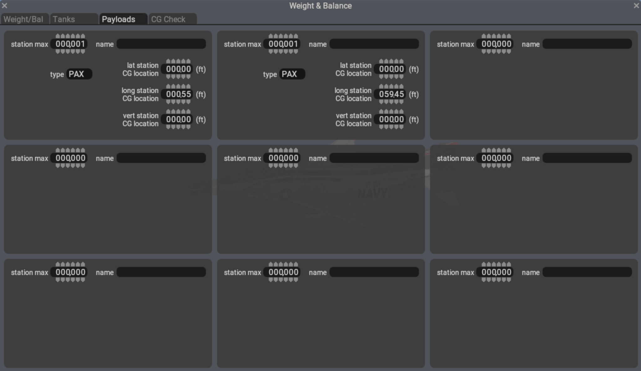
Limit Radii of gyration overrides
Mass in a payload station not only increases the mass of airplane and adds a moment, but the added mass also increases the moment of inertia around all axes if an offset from the empty CG location exists. Since loading a payload station increases MoI and thus radius of gyration dynamically (depending on how much weight the user actually loaded) it is preferable to use payloads with CG offsets rather than increase the radius of gyration.
Since X-Plane 11 considered payload a point-mass, authors often increased the radii of gyration to achieve a more “heavy” feel to the aircraft by adding more moment of inertia.
In X-Plane 12, the preferred way is to create multiple payload stations throughout the airframe that add moment of inertia dynamically as they get loaded.
Loading payload stations by datarefs
Each configured payload station can have mass added to it with the array dataref sim/flightmodel/weight/m_stations[]. The dataref is in kilograms.
The result of loading the stations is the total weight sim/flightmodel/weight/m_fixed and the CG offsets sim/flightmodel/misc/cgz_ref_to_default (in pitch) and sim/flightmodel/misc/cgx_ref_to_default (in roll), though the latter is usually only relevant to helicopters.
Writing to these datarefs will try to distribute the payload throughout the stations to achieve the requested CG and total mass, but it is not guaranteed that the requested CG can be achieved with shifting the available mass between the stations. For example, no negative mass will be assigned to a station to achieve more CG offset. It is thus recommended to read back the CG dataref after writing it to see the actually achieved CG after moving payload.
It is thus preferred to write the mass to the station and read the resulting CG.
Legacy aircraft with no configured stations
Upon loading an X-Plane 11 aircraft, X-Plane 12 will still consider the payload weight a point-mass and not alter moment of inertia. Two “virtual” stations in the nose and tail of the aircraft will be created to allow for a maximal arm to change the CG location. Payload mass will be distributed between nose and tail to achieve the requested CG. Note that these virtual nose and tail stations are not counted for moment of inertia.
Programmatically, you can detect these virtual stations by their fixed max weight sim/aircraft/weight/acf_m_station_max reading 1kg.
X-Plane offers several instrument types that display moving maps, the most popular one being map_s_HM.png which emulates an instrument found in airliners and allows for several display modes, like an HSI view, a NAVMAP view and a PLAN view.
Customization – graphics
Customization of the map display is possible by editing the map_s_HM-1.png, map_s_HM-2.png, map_s_HM-2.png and map_s_HM-4.png graphics and supplying the graphics specific for your aircraft through the library system (the path is cockpit/EFIS/EFIS_maps). These png files can supply alternate symbols, colors or fonts to generate the style of the navdisplay.
Up until X-Plane 11, it was not possible to change the overall scale of the map, so supplying a texture with bigger dimensions did not lead to bigger symbols or bigger text. Therefore, a very big map instrument would render very small and thus difficult to read symbols and text, even if the customized graphics were provided in a very high resolution.
Customization – parameters
Starting with X-Plane 12 it is possible to independently scale symbols and text of the navdisplay, and also change the relative locations of symbols and labels. The scale chosen is independent of the resolution of the supplied graphic files. Supplying a graphic with double the resolution will not increase the size of the symbols. Configuring the scale parameter to double the size will not increase the resolution of the texture, so the result will look blurry. To achieve a crisp and legible bigger navdisplay you will thus need to supply both a higher resolution texture and also configure a bigger scaling factor.
The customization parameters are supplied through a text file specific to the instrument that you supply for your aircraft in the path cockpit/EFIS/EFIS_maps. The name of the text file corresponds to the instrument, so if you are customizing the map_s_HM-3.png with new symbols, the text file to edit is the cockpit/EFIS/EFIS_maps/map_s_HM.txt.
The syntax of the file is as follows:
A
750 version
x   y
0 -143	// comment: rose offsets in expanded mode
0 -5	// comment: rose offsets in centered mode
2.5 2.5	// scale factor for symbol and text size
32 -15	// text label offset x and y in pixels at the provided scale
65280 -1 // 24bit color for the "magenta" line and absolute size of the compass rose
The first five lines are unchanged from previous versions of X-Plane and allow the lateral and vertical offset for the center of the map display in arc mode and rose mode. These pixel values continue to be unaffected by symbol scaling.
The next three lines are only read by X-Plane 12 and allow you to utilize higher resolution textures and further customize symbology.
The first scaling factor is applied to symbols and the second scaling factor is applied to text. They can be specified in single floating point precision. This way it is possible to scale text up more than symbols if needed for readability.
The last line provides the absolute offset from the center of the symbol to the bottom left of the text label attached to that symbol. In this example, the text label starts 32 pixel to the right of the center of a symbol and the bottom of the text label is 15 pixels below the center of a symbol.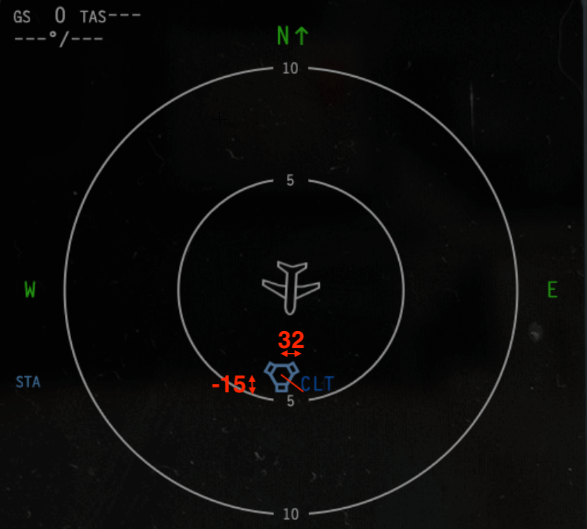
The last line allows customization of the ND MAP and plan mode where the FMS flightplan is displayed. By default, the active FMS route is a magenta line, but a 24bit value can be used to override the RGB value. In this example, 65280 is an RGB value of R=0, G=255 and B=0, thus a solid green line. The map scale is determined by the map range values of the array dataref sim/cockpit2/EFIS/map_range_steps in nautical miles, and the height of the compass rose texture (map_s_XX-3.png). If this is undesired, the array of available map ranges can be changed by plugin, and the size of “rose” can be altered independently from the texture by a non-negative value of the second parameter on the last line.