Terminology
X-Plane has two viewing modes for panels: a forward 2-d view that shows the 2-d panel and a 3-d view that shows the 3-d cockpit (which corresponds to the virtual cockpit in MSFS). Unlike MSFS, X-Plane does not provide multiple 2-d panel views – the 2-d side views may not contain working 2-d panels. X-Plane does not provide native support for popup panels, but it is possible to create them using a plugin or other tricks.
X-Plane’s panel consists of a background image (where alpha creates the transparent windshield) and a gray-scale or RGB overlay image that applies shadowing and some 2-d spot lighting to the panel. While MSFS has “gauges” X-Plane has “instruments” – the individual unit of placement.
Instrument Differences
The MSFS panel is created using an XML file; gauges can also be coded in C++ and can be in the form of *.dll or MSFS specific *.gau format.
X-Plane panels reside inside the ACF file in binary format (but can be exported as text from Plane-Maker); most panel editing is done using Plane-Maker’s near-WYSIWYG user interface.
X-Plane provides hundreds of types of instruments built in:
- Pre-made instruments model existing real world instruments; X-Plane ships with a complete set of real world instruments for VFR and IFR flight. Limited customization is possible by replacing bitmaps, and tuning a few parameters.
- Generic instruments provide basic “mechanism”, e.g. a needle that rotates, a button that toggles, etc. The generic instruments have a large number of customized parameters and visualize data from a “dataref” – that is, a sim variable from X-Plane itself or a plugin.
Therefore the closest thing to building gauges using the XML file is to build a panel out of multiple generic instruments. Typically a modern panel might be built primarily from generic instruments, but use the pre-built instruments for the moving map and a few other cases.
Custom Gauge DLL Vs. Plugin
While MSFS allows a custom gauge to be built via a DLL (where the gauge provides a bitmap of its 2-d image), X-Plane has a slightly more generic mechanism:
- An airplane can contain one or more plugins.
- Each plugin has full access to the X-Plane plugin SDK API – this includes building menus, custom UI and windows, creating and modifying sim variables, and drawing using OpenGL.
- Often the generic instruments can be customized by feeding a dataref from your plugin into the generic instrument – that is, the generic instrument rotates the needle (and X-Plane does the drawing) but the animation is keyed to output from your plugin.
- A plugin can also draw directly onto the panel – this happens on a panel-wide basis, not on a per-instrument basis. (This is how a complex custom nav display might be built.)
X-Plane does not provide a general mechanism to let an author “place” a custom plugin-drawn instrument into a panel using Plane-Maker; typically custom instrumentation is specific to a single plane. Where users have tried to build add-on instruments via plugins, they have had to create ad-hoc mechanisms to place those instruments.
The Virtual/3-d Cockpit
X-Plane’s 3-d cockpit environment is actually a rendering of the entire airplane in 3-d; all of the 3-d modeling work you do for airplane will be visible in the 3-d cockpit, allowing for the user to exit the VC and do a walk-around of the airplane. (See “Camera Restriction” below.)
Therefore the virtual cockpit is is simply modeled in 3-d using OBJ files, which contain meshes. Standard animation is used for instruments like steam-gauge airspeed indicators; this is similar to MSFS where a 3-d animation can be driven off of an animation source. Like MSFS, using “real animated 3-d” is often the fastest path for mechanical instruments.
X-Plane does have one “special” object (the “cockpit object”) that is intended particularly for VC work; it allows a 2-d panel to be UV mapped onto some 3-d surfaces, similar to using a material to indicate a 2-d panel mapping in MSFS. This work-flow is largely the same – you would create a snapshot of the “unwrapped” set of 2-d gauges (Plane-Maker can make this snapshot) and then UV map using it. The precise way to indicate “panel texture” depends on the 3-d editor you use.
Like MSFS, X-Plane provides a separate 2-d panel for the purpose of providing a material/texture for the 3-d virtual cockpit; therefore you can tightly pack this texture even if you want to ship a 2-d panel as well. In X-Plane, 2-d panels scroll and are often 2048 x 2048; it is important for performance to tightly pack the panel that is used in the 3-d cockpit.
Mouse-click interaction in the 3-d cockpit in X-Plane is annotated directly on the 3-d mesh; you mark a sub-section of the mesh with a “manipulator” describing what you want to have happen and the gesture. Typical manipulations include drags in 2-d or in arbitrary 3-d space, clicks, etc. Manipulations typically change an X-Plane dataref or run an X-Plane command (similar to an MSFS sim event) to affect the flight model.
Besides direct 3-d manipulation, you can mark any part of the 3-d mesh that has a panel texture mapped to it as “panel clickable” – this causes 3-d clicks to be passed through to the underlying 2-d panel, where the click operates as expected.
Things X-Plane Doesn’t Have Yet
Arbitrary Transforms
X-Plane can show and hide instruments but it cannot arbitrarily rotate or move them; there may be some XML transformations that are not yet possible in X-Plane. In many cases, a pre-built instrument will exist, and you can simply retexture it.
Things MSFS Doesn’t Have
Gradual Lighting Control
For any 3-d model in X-Plane, you can tie the level of the emissive (_LIT) texture using ATTR_lit_level, which arbitrarily scales the texture using a dataref. This has application for more realistic baked lighting, but can also be used to create gradual light faders in the 3-d cockpit or even to create instruments. (For example, the gear light LEDs can be made to appear by tying their lighting level to the gear status.)
Camera Restriction
You can restrict the movement of the camera in the 3-d cockpit by tagging a mesh as solid to the camera; this will stop your user from walking through the walls of the VC.
Use a hidden, simplified, manifold mesh to restrict the camera; the camera restriction will react better and use less CPU power with the simplified mesh.
You can use animations in your camera-restricting mesh. For example, if you animate the doors of your fuselage in the camera-restricting mesh, a user can exit the airplane only when the door is open.
See the default Cessna 172 in X-Plane for an example of this.
What are Non-Monotone Key Frames
Non-Monotone key frames are key frames where the key frame table is not in order. Here are some examples:
N1     ANGLE
0		50
50		270
100	230
This key frame table makes the angle of the needle increase as N1 goes up, but then the needle will reverse and go back down a bit. In this case, “angle” is non-monotone.
In this table for a a rotary;
enum   image
0		0
1		2
2		1
4		3
3		4
Both the input and output are non-monotone.
When Would I Want Non-Monotone Key Frames?
Generally you’ll want non-monotone key frames under two cases:
- If an instrument has to move forward and backward in response to data (e.g. the N1 needle example above).
- If you need to remap the enumerated values for a rotary (e..g the rotary example).
When Are Non-Monotone Key Frames Allowed?
- The value (but not dataref) key frame column can be non-monotone as long as the instrument reads but does not write the dataref. So non-monotone output can be used for a needle as long as it is not draggable, for example.
- Rotaries may have non-monotone key frames for both input and output, as long as values are matched _exactly_ without interpolation.
Previewing Non-Monotone Key Frames in Plane-Maker
Plane-maker recognizes that if you have out-of-order non-monotone key framing tables then you are probably intending to use a dataref that EXACTLY hits the key frame, like an int dataref that passes in enums. (You would use this to re-order the mapping between enums and rotary positions.)
In this case Plane-Maker will snap-round the simulated dataref to exact key frames so that you can see a sane preview of the dataref.
If you have done this but the dataref in x-plane is NOT rounded to key frames, you will then see wrong interpolation in x-plane, since we can’t cleanly interpolate non-monotone functions!!
Goals
- Creating liveries/repaints needs to remain simple. Repainting a plane is one of the simplest ways to make X-Plane content – this simplicity should not be lost.
- It should be possible to create a livery without copying airplane content. This is desirable for three reasons: (1) efficiency of implemetation, (2) enabling repaints while retaining content copyright and (3) allowing the author to update the core plane without repainters having to re-copy modified art assets.
Bug Fixing
- If an aircraft package contains multiple aircraft files, liveries will be available to all of them. If the aircraft files represent different configurations (E.g. P&W vs. RR engines) a livery might be appropriate for one aircraft file but incomplete for another. Requested: some way to “limit” a livery to certain aircraft files in a package.
- The tail number is part of the ACF file, but may change due to paint changes of an aircraft. Requested: a way to specify the tail number per livery.
Configuration Management
Airline authors would like to give repainters a choice of “cosmetic” (meaning they do not affect the FM) options for the airplane – this would include things like antenna placement and window location, but would not include things like engine selection or winglets. These cosmetic options would be created by the primary airplane author – the livery repainter would simply select the appropriate parts for the livery in question. (For example, a painter creating a British Airways livery would select Rolls Royce engines to match the real world planes.)
Livery Configuration Files
Proposed: a text file in the livery would provide a storage location for additional per-livery data. This file would be a simple keyed record file (like all X-Plane text files). The file wold have a package specific name like livery.txt, not an aircraft specific name, like ba20_livery.txt.
(This is because the livery might be shared across multiple configurations – file-specific liveries are discussed below. However, consider a Cessna 172, offered in two configurations – with or without G1000. This 2-d panel change would not affect repaints, thus the desire for package-wide liveries.)
Livery configuration files could be written by painters, or (more likely), if a plane author provides a “repainting kit” with starter images, annotated UV maps, etc. then a livery configuration file would be provided in the painting kit that would be customized by the painter.
Configuration File Options
File Matching
If present, a key would specify what ACF files the livery matches for. If no keys are present, the livery can be use for any file. Example:
REQUIRES_FILE b747-400.acf
Tail Number
If present, overrides the tail number for the ACF.
TAIL_NUMBER N4772Q
Object Mapping
The object mapping would allow the livery to remap what objects are attached to the plane, by specifying a file name substitution scheme. The intent is that the airplane author would attach the “default” objects for a configuration in Plane-Maker, but provide alternate objects that could be mapped.
Example:
# This selects to use the "direct_tv.obj" antennas OBJ instead of the regular
# antennas.obj.  A painter who wants to have the appearance of direct TV on the
# plane might include this mapping.
MAP_OBJECT antennas.obj antennas_direct_tv.obj
OPEN ISSUE: this could go in one of two ways:
- The above scheme, which lets the painter remap objects directly or
- A scheme in which the primary airplane author enumerates legal combinations and the painter picks from among them. In this second option, the livery might only contain
CONFIG_CHOICE antennas direct_tv
Where the meaning of the option and its legal configs were defined in the ACF package itself.
- Advantages: slightly simpler liveries – livery authors don’t need to know where objects live and what is meant to go with what.
- Disadvantages: whole system becomes more complex, including complexity in the main package.
Ben says: I was originally in favor of choice 2, but Peter has me leaning toward choice 1 for overall simplicity.
Authoring Information
Perhaps the livery should contain authoring information, e.g.
LIVERY_AUTHOR John Wharfing
LIVERY_COPYRIGHT Copyright 2008, All Rights Reserved.
A manipulation is an action the user can take by clicking on your object. (That is, the user “manipulates” your OBJ with the mouse.) Manipulations can only be used on cockpit objects!
Types of Manipulators
There are six types of manipulators supported in X-Plane 920 and later:
- None
- Panel Click
- Drag-Axis
- 2-d Drag
- Command
- Command-Axis
- Opaque
No Manipulation
Triangles are ignored when clicking. This is the default, and is usually used for anything that is not clickable. This manipulation does not require any CPU resources, so when possible, you want to leave your meshes non-manipulatable. This is the only legal manipulation for non-cockpit objects.
The none manipulation is set using either
ATTR_no_cockpit
ATTR_manip_none
The none-type manipulation will show no tool tips, and uses the arrow (default) cursor.
Panel Click Manipulation
A click on the triangles is mapped through to the 2-d panel based on the panel texture’s mapping. This manipulation can only be specified for objects that are textured by the panel texture (or a panel texture region). Panel click manipulation is set using one of
ATTR_cockpit
ATTR_cockpit_region <region number>
Panel click manipulations show the tooltips and cursors of the 2-d panel.
Drag-Axis Manipulation
As the user drags along an axis in 3-d object-space, a dataref value is increased or decreased. The length of the axis defines how much mouse travel (in meters of object space) is required to completely change the dataref across a range defined by a pair of parameters. The drag-axis manipulator takes the form:
ATTR_manip_drag_axis <cursor> <x> <y> <z> <value1> < value2> <dataref> <tooltip>
Here, x, y and z define the length and direction of the drag axis, and value1 and value2 define the range of values over which the manipulator runs. If the mouse is dragged beyond either of these limits, the manipulator is clamped: the value of the dataref will remain the same until the mouse is again dragged or clicked within range. The current value is retained after the mouse is released, and determines the position of the manipulator’s drag-axis relative to the next mouse click. For example, if a manipulator is currently set to a value midway between it’s minimum and maximum values, then the mouse will automatically find itself halfway along that manipulator’s drag-axis when next it clicks on it.
Drag-axis manipulation is subject to object animation. The orientation of the manipulator’s drag-axis relative to the animated mesh to which it is attached is the same each time the mouse is clicked on it. For example, if a drag-axis manipulator on an animated throttle lever has an axis perpendicular to the lever shaft when clicked in the ‘idle’ position, that axis will still be perpendicular to the lever shaft when clicked in the ‘open’ position. However, for the duration of any given drag, the orientation of the drag-axis relative to the aircraft remains constant. So if the drag-axis of the previously-described manipulator happens to be perfectly horizontal at the moment the mouse is clicked on it, it will remain perfectly horizontal and ‘locked-in’ until the mouse is released, even though the visible throttle lever has been animated to a new position. This behaviour is more intuitive in practice than it may appear on paper!
2-d Drag Manipulation
The 2-d drag manipulator effectively combines two manipulators into one, allowing two datarefs to be modified simultaneously by dragging the mouse along a pair of perpendicular axes. To minimise input ambiguity, the axes are defined in 2-d screen space, not object space, and their respective orientations are fixed. The first dataref is modified by dragging the mouse horizontally across the screen and the second by dragging vertically. This type of manipulator would typically be used to control a yoke or joystick and takes the form:
ATTR_manip_drag_xy <cursor> <x> <y> <ref1 value1> <ref1 value2> <ref2 value1> <ref2 value2> <dataref1> <dataref2> <tooltip>.
Here, x defines the distance the mouse must be dragged across the screen from left to right in order to modify the output of dataref1 from ref1 value1 to ref1 value2. Similarly, y defines the distance the mouse must be dragged up the screen in order to vary the output of dataref2 from ref2 value1 to ref2 value2.
In contrast to the drag-axis manipulator, the axis orientations of the 2-d drag manipulator are not subject to object animation. The x-axis is always horizontal and the y-axis is always vertical. However, the location of the manipulator’s click-region does follow any animation of it’s mesh.
The following example shows a 2-d drag manipulator configured to control a steering yoke. The x-axis controls roll (an 80-pixel drag), and the y-axis controls pitch (a 50-pixel drag). Note: since it is more intuitive to drag down rather than up the screen in order to increase pitch, the vertical axis has been assigned a negative value):
ATTR_manip_drag_xy four_arrows 80 -50 -1 1 -1 1 sim/cockpit2/controls/yoke_roll_ratio sim/cockpit2/controls/yoke_pitch_ratio I am a tooltip.
It is not obligatory for a 2-d drag manipulator to address two datarefs. A single dataref may be manipulated in 2-d screen-space by entering a value of 0 for each of the redundant numeric parameters and null for the dataref name of the unassigned axis.
Command Manipulation
A command manipulation invokes an X-Plane command when the mouse is clicked on it. The command continues to be invoked until the mouse is released. It takes the form:
ATTR_manip_command <cursor> <command> <tooltip>
Command-Axis Manipulation
Dragging along a specified object-space axis actuates one of a pair of commands, subject to the direction of the drag. The command continues to be invoked (CommandContinue phase) until such time as the mouse is either released or else dragged back along the axis to the neutral position. Dragging right through the neutral position to the opposite end of the axis invokes the second command. The neutral position is centred on the location of the original mouse click and occupies 40% of the overall length of the axis Typical applications would be nudge-wheels and three-position toggle switches. The command-axis manipulator takes the form:
ATTR_manip_command_axis <cursor> <x> <y> <z> <command1> <command2> <tooltip>
The x, y, and z parameters define the orientation and length in meters of the drag-axis. Dragging in the positive direction triggers command 1 and in the negative direction, command 2. The following example shows a command_axis manipulator configured as a pitch trim nudge-wheel/switch:
ATTR_manip_command_axis up_down 0.00 0.00 -0.01 sim/flight_controls/pitch_trim_down sim/flight_controls/pitch_trim_up I am also a tooltip.
The axis values in the above example would be appropriate for a standard-sized toggle switch mounted on a horizontal console panel. Dragging the mouse approximately 2mm towards the nose of the aircraft triggers pitch_trim_down, and dragging it 2mm towards the tail triggers pitch_trim_up (since the X-Plane acf z-axis runs positive nose to tail).
Opaque Manipulation
This sets the manipulation to ‘no-op’ (no operation). Unlike “none” manipulation, opaque manipulation “swallows” the mouse, preventing it from clicking on other manipulators that may lie behind it. It would typically be used to act as a safety-guard over a switch.
Dataref “Button” Manipulators
These manipulators change a dataref when the mouse is clicked or held, creating button-like functionality. There are five sub-flavors. The push-button, radio button, and toggle manipulators are meant to provide button-like behavior for a mesh. The delta and wrap manipulators are meant to be used to create invisible “hot spots” over a mesh.
Push-Button Manipulator
The push-button manipulator sets a dataref to a “down” value when the mouse is clicked, then back to an “up” value when the mouse button is released.
Radio Button Manipulator
The radio button manpiulator sets a dataref to a value each time it is clicked.
(It is considered to be a “radio button” because a set of these manipulators, sharing one dataref but using differing values, can create radio-button-like behavior.)
Toggle Manipulator
The toggle manipulator switches a dataref between one of two values each time it is clicked.
Delta Manipulator
The dataref is increased (or decreased) when the button is clicked (and/or held down). If the dataref exceeds its limit range, it is clamped to that limit.
Wrapping Manipulator
The dataref is increased (or decreased) when the button is clicked (and/or held down). If the dataref exceeds its limit range, it wraps around to the other end of the range.
Manipulator Properties
These properties apply to some or all of the manipulators except for:
- None and opaque manipulators (which have no real action).
- Panel manipulator (which gets its properties from the panel).
Cursor
All manipulators let you specify the cursor that appears when the mouse is over the manipulator. (The panel manipulator takes its cursor from the underlying panel.) The OBJ8 specification lists all possible cursor choices.
3-D Axis
The axis and command-axis manipulators allow a drag in 3-d; they require the specification of an axis.
- The axis is a 3-d axis, so it is specified as a length in X, Y, and Z (in meters).
- This axis is affected by animation; if the manipulator is inside a rotation, the axis will rotate.
- The axis manipulators imply an “increasing” and “decreasing” direction; the values specify the increasing direction.
EXAMPLE: for an axis of X = 1, Y = 1, Z = 0, as you drag to the upper right (in object coordinates) the dataref will increase.
The axis’s position in the 3-d cockpit is set based on the current value of the dataref when the user clicks. For example, if the dataref for the axis manipulator is the throttles and the throttles are at maximum value, the entire axis will be in the direction to decrease the throttles. If the throttles are at 50%, the mid-point of the axis will be at the click point. In other words, axis positioning is relative based on the dataref.
(For the command-axis, the axis center is always the anchor point.)
2-D Axis
The 2-d drag axis is a special case: it allows a drag in “screen space” – that is, the axes is always up-down and left-right no matter what the pilot head position. Thus the axes are lengths in pixels. A positive “x” means that a drag to the right increases the first dataref. A positive “y’ means a drag up increases the first dataref.
Datarefs and Values
For the axis and axis-2 manipulators, one or two datarefs is required, as well as low and high values. The low and high values “scale” the axis. For example, for a throttle, a low and high value of 0.0 and 1.0 would tell the manipulator what throttle values correspond with the end of the axis.
(In other words, the axis specifies the size in the 3-d cockpit of the drag, and the dataref values specify the size in terms of the actual dataref movement.)
Commands
A command can be specified for either the command manipulator (the command is invoked while the mouse button is held down) or the command-axis dataref (the command is invoked while the drag is to the left or right of the axis).
Tooltips
All manipulators let you specify a tooltip. When the mouse lingers over the manipulator region and the user enables “instrument explanations”, this tooltip will be shown. It provides a way to provide custom panel instructions. Tooltips may not have return characters. (For the panel manipulator, the tool tip is taken from the underlying 2-d manipulator.)
Setups For Typical Switches and Elements
Here are some typical setups for making 3-d animated switches and other cockpit parts.
Terms
- Rotary: any part with rotational movement.
- Momentary: any part that returns to its original position when released.
- 2-way,3-way,n-way, continuous: how many distinct positions a part can take. A dimmer is continuous; an on-off switch is 2-way.
Non-Momentary Parts
These parts retain their original position after being clicked.
2-way parts
Datarefs: use the “toggle” manipulator – the on and off values match the two possible values for the underlying dataref.
Command: if a “toggle” command (e.g. sim/flight_controls/landing_gear_toggle) exists, you can use a command manipulator. You cannot use a “set to X” command like sim/flight_controls/landing_gear_up.
N-way switch
Use the axis manipulator along the axis the user can drag. Important: to get “N”-way action, be sure the underlying dataref is of type “integer” so the switch “snaps” to each position.
N-way rotary
Use the 2-d axis manipulator, but only use the X axis. This will allow a horizontal drag to turn the rotary. To get “N”-way action, be sure the underlying dataref is of type “integer” so the switch “snaps” to each position.
Radio Buttons
Radio buttons can take on N positions, by having any one button pressed in. Set each button to have a manipulator of type “radio button”. All buttons should have the same datarefs but different values.
Continuous Switch
Use the axis manipulator along the axis the user can drag. The underlying dataref should be of type “float”.
Continuous Rotary
Use the 2-d axis manipulator, but only use the X axis. The dataref should be of type “float”.
Momentary Parts
These parts snap back when done.
2-way momentary
Dataref: use the “push button” manipulator with appropriate on and off dataref values. Command: if the action is a “hold-it-down” command (like sim/starters/engage_starter_1) you can use a command manipulator.
3-way momentary
Use the command-axis manipulator, with one command for each direction.
This RFC is a proposal to allow nested animation via groups in the panel/instrument system.
Under this proposal:
- Groups would have an animation mode, which would be one of: none, rotation, or translation.
- If a group’s animation mode was not “none” the group would have a primary dataref and key frame table. The key frame table’s output would be in pixels (translation) or degrees (rotation).
- If a group’s animation mode is translation, the group would also have an “axis” property defining the direction of translation (as a DX, DY).
- All sub-groups and instruments within the group would be affected by the animation.
Instruments in X-Plane are positioned based on their center position. Because an instrument with an odd width or height might have a center that is a fraction of a pixel wide, fractional instrument coordinates are allowed.
Guidelines
Here are some guidelines for positioning your instruments for maximum visual quality:
- For best quality, leave the instrument scale at 1.0. If you scale the instrument, the graphics card will blur your art. To make a small instrument, use small artwork!
- The base layer and overlay layers should all have the same even-odd status. In other words, if your base instrument texture is 57 pixels wide, your overlay should not be 54 pixels wide. All widths and heights should be either all-odd or all-even.
- If your textures are even, your instrument should be centered on a whole-pixel position, e.g. (254.0, 127.0).
- If your textures are odd, your instrument should be centered on a half-pixel position, e.g. (254.5, 127.5).
- When these rules are followed, Plane-Maker’s preview should match X-Plane when the panel is not scaled.
- If you violate these rules, the particular visual errors you get will vary based on the particular instrument, the type of alignment mistake, and possibly even your graphics card.
Test Airplane
This test airplane package demonstrates all possible instrument alignment combinations for non-scaled instruments, both correct and incorrect. Download the zip file here.
This picture illustrates the panel test:
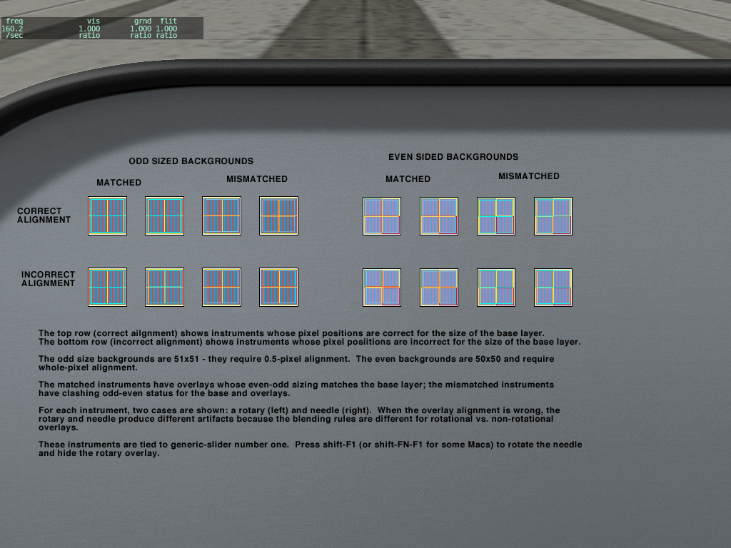
Some notes:
- When an instrument is misaligned, there may be no visible error, a full pixel error, or in the case of rotating panels, blurry pixels.
- The error may be different for each layer of the instrument.
Mutli-format font support
- The generic-text instrument would be able to take a font bitmap with more than one line.
- Each line could be used for a different font, different size, or different color text.
- Control codes (ASCII 1-31) in a string DataRef (char-array type DataRef) would be interpreted as style changes. A line in the text would be selected by running the control code through the instrument’s key frame table.
OPEN ISSUE: where would line size and line formatting information be stored?
- These could be in the instrument.
- They could also be in a text file co-named with the PNG. This is a bit atypical of the generic instrument system, but since the PNG is a shared resource, it makes development simpler to have the metrics be shared too.
Text-font-based Numeric
- A new gen_numeric instrument would use the same font formatting rules as the gen_text, for shared fonts, but use numeric datarefs.
- The key frame table would do numeric conversion.
- Numeric formatting would be by property (similar to the LED and rolling instruments).
- Color selection would be done via range bounds, similar to the pie instrument (e.g. different stripes could be selected based on five zones of dataref values).
OPEN ISSUE: should it simply be legal to allow the gen_text instrument use numeric datarefs? Pro: reduces number of instruments Con: key frame table acts differently, properties needed are very different too!
The Rotary
- The rotary can be used as a single image layer, but with dynamic lighting. Set it to no click, one image.
- Rotary can be used behind an image to get “dynamic lighting” onto a background. (But – don’t make it too large – spot lights affect overlays UNIFORMLY. Burns VRAM. No shadows!)
- Rotaries can be used with rheostats – set the rheostat to no -1 layer on top of the rotary with no click, customize hot spots. Same trick works with triggers.
- Put a rotary (no click 1 phase) as a face plate over a pointer, but set the pointer itself to clip, to ensure that if the pointer exceeds its “masks” bounds it disappears.
- Key frames must be continuous EXCEPT for rotaries – use to re-arrange enums. See Non-Monotone Key Frames.
- Rotary key frame output < 0 means it disappears. Use for annunciators. Don’t need transparent frame. Save VRAM.
- Rotary key frame > digits WRAPS. USe for repeating animation like trim wheel.
Using Rotaries With Plugins
You can use a rotary as a way to get “mouse clicks” in a plugin:
- Set the rotary mode to “momentary”.
- Create a custom dataref handler.
- Your dataref’s “set” handler will be called once on a down click and once on an up click. The down click will have a value of the number of frames – 1, and the up will have a value of 0.
There is one complication with this method: if you are using the “get” function from your rotary to make the light flash, then you may not receive “set” messages, because the sim won’t write back to your dataref the same value you returned. (Thus if you use “1” for “lit”, you won’t get down-clicks in a 2-phase rotary.)
The solution: rotaries will modulo their number of frames. So for a two-phase rotary, return 2 & 3 from your plugin, instead of 0 and 1. The graphics will look the same, but you will still get writes of “0” and “1” on click.
Driving The Same Dataref With Multiple Rotaries
You can use multiple “push-button” rotaries to set the same dataref between two values. For example, say you want to have (3) push-buttons on your panel and they all set the dataref between zero and another value as follows:
- Push-button #1 to drive the dataref to either 0 or 1,
- Push-button #2 to drive the dataref to either 0 or 2
- Push-button #3 to drive the dataref to either 0 or 3.
You would set the gen_rotary properties to Positions = “2” and Rotary Type = “Push Button”. Your graphic image should be designed with two (2) phases.
You should then set-up the key frame table as follows:
For Button #1:
Dataref Value ––––––––—–––– Image Number
          0                            0
          2                            0
          3                            0
          1                            1
For Button #2:
Dataref Value ––––––––—–––– Image Number
          0                            0
          1                            0
          3                            0
          2                            1
For Button #3:
Dataref Value ––––––––—–––– Image Number
          0                            0
          1                            0
          2                            0
          3                            1
When a button is pushed, X-Plane looks for Image #1 in the key frame table (the highest image for a 2-phase image) for that button and notes what the dataref should be set to by the associated “Dataref Value”. At the same time all other buttons with that dataref are set to zero.
All of the enum values for the dataref must be individually listed in the keyframe table (you cannot set up a range). The last key frame needs to be the “1” frame.
Glass vs. Translucent Glass
X-Plane has two modes of glass instrument lighting. Both take the light levels from an instrument light level rheostat and light the instruments overlays, ignoring spot lighting. The difference is in how they fade:
- Glass instruments are opaque except for their alpha channel, drawing over what is behind them. As they get dark, they fade to black. Thus they can be used to form masks as well as glass instruments, but they will only appear to blend in over a pure-black background.
- Translucent Glass Instruments draw additively – the alpha channel is not needed and has no effect. As they get “dark” they become more translucent – that is, they add less. They cannot be used for masks, but they will draw over any background, allowing for screen backgrounds that are not pure black.
Needles
- Generic needles can be offset – save VRAM!
- Needle can act as a heading bug, via offset and drag.
Rheostats
- Rheostats can have overlays – save VRAM.
- Set rheo step 2 to 0 to get incremental movement.
Pie
- You can customize the colors of the pie – the-2 overlay image has 3 color swatches for the “green”, “yellow” and “red” tinges, which are chosen based on the dataref range. So you can pick any color for your pie.
- If you ned more than 3 colors, make two overlapping pies and use show-hide to switch between pies at certain dataref ranges.
- You can make a pie that is a thin line rather than thick by putting a black pie in front of the white pie, but give the black pie a smaller radius. After 930 you can simply use the offset parameter.
Groups
After X-Plane 930 groups can be hidden using filters. This can be used in a few ways:
- If you need more filters (E.g. hide an instrument based on a number of conditions) simply put the instrument into a group – now you can filter the instrument or the group.
- You can hide non-generic instruments by putting them inside a group.
Pointer Instead of Rolling For Tapes
gen_rolling is meant for a mechanical drum style instrument but it will not work if a large section of the “drum” is visible…thus while it seems that it should be usable as a tape, it is not. (The instrument does not work as a tape because not enough “extra” texture is provided at the top and bottom).
After 940 you can use a vertical pointer with a wrapping key frame table to make a looping tape.
Misc
- Key frame tables can be clamped by doubling an output value, e.g. (-1,0) (0,0) (1,1) (2,1)
- You can also clamp one side of a key frame table and wrap the other side. To do this you’ll need to repeat a value. For example: (0,0) (0,0) (100,100) will make a key frame table from 0->100 that can be wrapped at the top but will clamp at the bottom.
You can download the example plane here: File:Example beacons.zip.
Overview
This example plane demonstates some of the airplane exterior lighting features that are possible in X-Plane 9:
- Left and right landing lights are separately controlled.
- Landing lights have two intensity levels (low and high).
- Landing lights illuminate the fuselage of the airplane.
- Logo lights illuminate the tail (billboards are visible on the wing-tips).
- Strobe pattern is customized.
- Front and rear wing strobes flash separately.
- The two rotating beacons rotate at different rates.
This tutorial covers the following X-Plane material:
- Parameterized Lights
- Datarefs for light control
- Use of ATTR_light_level
You Should Already Know
To understand this example plane, you should already know:
- How to model a plane in Plane-Maker.
- How to create a panel, including generic instruments.
- How to build the exterior out of OBJ files from a 3-d modeler.
- How to attach “named lights” to create lighting billboards.
This tutorial focuses mostly on billboards and halo effects; you can build light fixtures in a 3-d modeling program.
Landing Lights
X-Plane simulates up to 16 separately controllable landing lights (plus one taxi light). You can use named lights to map any number of billboards to any of these simulated lights.
If any of the 16 landing lights is on, X-Plane will draw a landing light halo effect on the runway in front of the airplane. (The quality of this effect will vary with hardware capability.)
The location of the landing light halo effect on the pavement is determined by the landing light location in the Plane-Maker view dialog box’s exterior lights tab.
Note: Even if you do not enable the landing lights in this tab, the location of the halo will be determined by this. X-Plane draws only one halo, so if you do not enable these lights, set the first light’s location to something appropriate for the centerline of the airplane.
Data Refs
The dataref
sim/cockpit2/switches/landing_lights_switch
is an array of floating point values that you can use to turn the landing lights on and off. The landing light switch is a ratio with 0 being off, 1.0 being full intensity, 0.5 being 50% intensity, etc. Each landing light can be set to a different intensity, or be individually turned off and on.
The dataref
sim/flightmodel2/lights/landing_lights_brightness_ratio
Tells the actual effective brightness of the landing light for visual effects – it takes into account electrical system and landing light failures, as well as the delay for the bulb to warm up and cool down. It is also an array of 16 floating point values – 0.0 is off, 1.0 is full brightness.
There are two legacy datarefs:
sim/cockpit/electrical/landing_lights_on
sim/cockpit2/switches/landing_lights_on
That date back to older versions of X-Plane. Use the newer datarefs for more control – these datarefs will turn all of the landing lights on and off at once.
3-Way Panel Switches
X-Plane comes with a built-in “landing light” switch – don’t use it. It will only affect the first landing light. Instead, use generic instruments to write to the sim/cockpit2/switches/landing_lights_switch switch.
In our plane, we use a 3-position rotary. A key frame table matches the 3 positions to off, 50%, and 100% brightness.
Customizing the Landing Light Billboards
For the billboards under the wings, we do not use the built-in landing lights from the view dialog box of Plane-Maker. Instead we attach parameterized lights to our OBJ.
A parameterized light is like a named light: it is a billboard attached to your object at an XYZ location. The name defines what the billboard will look like. But unlike a named light, a parameterized light lets us customize the look of the light. Our object contains this:
LIGHT_PARAM airplane_landing_size -0.822960 -0.152400 1.737360	1.5	-3 0
LIGHT_PARAM airplane_landing_size 0.822960 -0.152400 1.737360	1.5	-3 1
The first 3 numbers are the location in meters relative to the attachment point of the fuselage object that the lights are part of. The next numbers meanings depend on the type of parameterized light. In our case (landing light by size) they are:
- The size of the billboard (1.5). Billboard sizes don’t correspond to meters – you’ll have to experiment to find appropriate sizes.
- The tightness of focus. Negative values are visible from the front of the plane, positive from the rear. Larger magnitude numbers make a light that is visible from a smaller angle.
- The index number of the light. So the first billboard on the left side is tied to landing light #0, the second one is tied to landing light #1. (Array indices for datarefs count from 0.)
Thus the two landing lights are independently controllable.
Note that you can make many light billboards (with LIGHT_PARAM or LIGHT_NAMED) for a single x-plane landing light. So for example, you can model a landing light in a wing with several bulbs.
Adding Halos To The Fuselage
To create the illusion of the landing light shining on the fuselage, the _LIT texture for the fuselage object has the lighting halos for the two landing lights and tail drawn in.
We can use ATTR_light_level to control the brightness of the light texture for a certain set of triangles. What makes things difficult is that we can only have one _LIT texture. So it is important that we design our lights with no overlapping regions. (We have no way to select one of multiple halos that would intersect in the LIT texture.) In our object we have this:
ATTR_light_level 0.000000 1.000000 sim/flightmodel2/lights/landing_lights_brightness_ratio[0]
TRIS 0 882
ATTR_light_level 0.000000 1.000000 sim/flightmodel2/lights/landing_lights_brightness_ratio[1]
TRIS 882 669
ATTR_light_level 0.000000 1.000000 sim/flightmodel2/lights/generic_lights_brightness_ratio[0]
TRIS 1551 435
The mesh is divided into three parts, and each part has its lit level tied to one of the brightness ratios – two for the landing lights, one for the tail logo lights (see below).
Note that we do not use the switch datarefs, we use the filghtmodel2/lights/ datarefs to get the actual brightness. This way if our electrical system dies, the halo effect will disappear from the fuselage even if the switch is turned to the “on” positions.
Tail Logo Lights
The tail logo lights basically repeat the strategy we used for the landing lights, but with one difference: we don’t want a halo to appear on the runway because the logo lights are turned on. But we get a halo on the runway if any landing light is turned on. Clearly we can’t “recycle” one of our 14 remaining landing lights for the tail.
Fortunately, X-Plane also provides 64 “generic” lights. A generic light is a bulb simulated in X-Plane, similar to a landing light, but without producing a halo effect on the runway. We can use them for any purpose. In our case we will use a generic light to simulate logo lights projecting back from the wing tips to the tail.
Something to note: while our plane appears to have two logo lights (one on each wing tip lighting each side of the tail) we only use one generic light for both. This is because we don’t model turning the left and right logo light on separately. Thus we can just use one generic light, and use two billboards. There is no requirement to use one generic light in X-plane for each real-world bulb on the plane.
Data Refs
Like the landing lights, two datarefs control the generic lights. The switch position is also a ratio from 0.0 to 1.0:
sim/cockpit2/switches/generic_lights_switch
and the brightness (taking into account the electrical system, etc. is found in
sim/flightmodel2/lights/generic_lights_brightness_ratio
where 0.0 is off and 1.0 is full brightness.
3-Way Panel Switches
There is no pre-made instrument switch for generic lights – we must use a generic instrument (in our case another 3-way rotary) to map to sim/cockpit2/switches/generic_lights_switch.
Adding Halos To The Tail
Like the landing lights, we use ATTR_lit_level to fade the _LIT texture on the tail.
Adding Billboards To The Wing Tips
We want to put a pair of billboards on the tails so that when a user looks from the tail to the wing-tip, the bulb appears. Once again we use parameterized lights so we can customize the light’s properties a bit. But here we have a problem: the parameterized lights only face forward or backward. How do we angle the lights inward toward the tail?
The answer is animation. Directionally sensitive billboards in X-Plane are affected by animation. We can build a “static” animation (an animation whose animated position never changes) to “aim” the billboard at the tail.
ANIM_begin
ANIM_trans -4.906825 0.121920 2.7 -4.906825 0.121920 2.7 0.000000 0.000000 none
ANIM_rotate 0 1 0  250 250    0 0 none
LIGHT_PARAM airplane_generic_size 0 0 0	1.5 -3 0
ANIM_end
ANIM_begin
ANIM_trans  4.906825 0.121920 2.7 4.906825 0.121920 2.7 0.000000 0.000000 none
ANIM_rotate 0 1 0  120 120    0 0 none
LIGHT_PARAM airplane_generic_size 0 0 0	1.5 -3 0
ANIM_end
The lights are being rotated around an arbitrary point, 250 degrees for the first light, and 120 degrees for the second.
Beacons And Strobes
For our airplane, we want to accomplish a few specialized effects with the beacons and strobes:
- We want the strobes to flash in an irregular pattern (short long, short long).
- We want the first flash to come from the front of the wing, and the second one to come from the back of the wing.
- We want the two red rotating beacons to flash at different rates.
X-Plane 940 models four separate strobes and four separate beacons. Normally they will all flash or rotate in sync in a preset pattern. But we can use a plugin to take over the behavior and program our own pattern. So we have a 2-part task:
- Program our own pattern, and
- Use parameterized lights to place strobes and beacons on our airplane OBJ that respond to the right strobe or beacon number.
Parameterized Lights For Beacons and Strobes
Once again, we will not use the built-in exterior lights; instead we will place our own in an OBJ. In the exterior lights tab of the view dialog box in Plane-Maker, all of the specific lights are off, and the options to have Plane-Maker place lights for us is off too.
In our fuselage object file we have:
LIGHT_PARAM airplane_beacon_size 0.000000 0.643128 0.000000 1.5 0 0
LIGHT_PARAM airplane_beacon_size 0.000000 1.594104 3.383280 1.5 0 1
This is a pair of rotating beacons; these are parameterized lights. The first parameter is size. The second parameter (0) makes the light omni-directional. And the third light is the index number of the 4 beacons. So the second beacon is on the tail, the first is on the fuselage.
(Note that unlike landing lights, all four beacons simulated in the system are controlled by one switch. The same applies for the strobes.)
Our nav lights on the wing tips are simple named ilghts
LIGHT_NAMED airplane_nav_left -4.906825 0.121920 2.197132
LIGHT_NAMED airplane_nav_right 4.906825 0.121920 2.197132
Finally, the strobe wings. We have two on each wing-tip.
LIGHT_PARAM airplane_strobe_size -4.906825 0.121920 2.097132 2 -0.25 0
LIGHT_PARAM airplane_strobe_size 4.906825 0.121920 2.097132 2 -0.25 0
LIGHT_PARAM airplane_strobe_size -4.906825 0.121920 2.397132 2 0.25 1
LIGHT_PARAM airplane_strobe_size 4.906825 0.121920 2.397132 2 0.25 1
The first parameter is size, the second directionality (again, negative means “visible from the front”, and smaller numbers are less directional), and the last number is the index of the strobe. So the front strobe is index 0, the back strobe is index 1.
Again, note that the number of strobes that the sim simulates is not the same as the number of billboards. We have two strobes, but we have two billboards for each (one on each wing). So the system simulates two strobes (for a two-stage flash) but we see four billboards.
DataRefs And Plugin
Without the plugin, the strobes would flash all four in sync, once a second, and the beacons wouild flash in unison. We use a fat plugin in the aircraft’s plugins folder to override this behavior.
The full source of the plugin and complete downloadable project files an be found on the X-Plane SDK website:http://www.xsquawkbox.net/xpsdk/mediawiki/Beacons_and_Strobes.
These are the datarefs that affect strobe and beacon operation:
sim/flightmodel2/lights/override_beacons_and_strobes
When you set this dataref to 1, you take control away from X-Plane and manage the strobes and beacons yourself. You must manage both – there are not separate overrides for beacons and strobes. Be sure to set the dataref back to 0 when your plugin is unloaded!
X-Plane will set these datarefs to be 1 if the beacons and strobes have power and 0 if they do not:
sim/cockpit/electrical/beacon_lights_on
sim/cockpit/electrical/strobe_lights_on
Use these datarefs (and not the raw switch datarefs) to decide whether the strobes and beacons should light up – that way your strobes and beacons won’t work if the battery or electrical system fails.
These datarefs are updated by X-Plane once per frame, unless you override the beacons and strobes; in that case your plugin must update them.
sim/flightmodel2/lights/beacon_brightness_ratio
sim/flightmodel2/lights/strobe_brightness_ratio
sim/flightmodel2/lights/strobe_flash_now
The brightness ratios are 4-item float arrays – 0 means off, 1.0 means full brightness. The default beacons and strobes that Plane-Maker creates always show index 0, but you can use parameterized lights to show the other indices.
strobe_flash_now is an int – set it to 1 if any of the strobes is flashing; X-Plane checks this dataref and creates a “flash” effect in the cockpit when you are in the clouds or fog and the strobes are on.
X-Plane 940 allows you to customize the look of the prop disc using a series of datarefs. The idea is to allow a plugin installed in an airplane to provide the rules for prop disc rendering, while letting X-Plane deal with the details of z-buffer thrash and other prop-disc-related artifacts.
Authors who want detailed 3-d props (when not spinning) should continue to build these with a 3-d modeler and turn off the “draw plane part”.
A sample plugin that controls the prop disc datarefs can be found here: http://www.xsquawkbox.net/xpsdk/mediawiki/Custom_Prop_Disc
You can download a sample airplane with a custom prop disc driven by a plugin here: File:Example prop disc.zip.
Concepts
A prop is either a disc or not. In disc mode the physical prop is not drawn – instead one or two proxy textures are drawn to simulate the effect of the prop spinning rapidly.
When the prop is not a disc, X-Plane will draw an airfoil for each blade, unless the plane part is disabled for drawing in Plane-Maker.
The prop disc is made up of two parts: the front disc and the side billboard. (The side billboard is not used unless a plugin activates it.) The front disc is a quad normal to the longitudinal axis; the side billboard is a quad normal to the lateral axis. Both spin around the longitudinal axis.
The prop disc texture is used by dividing it into equally sized cells horizontally and vertically and then selecting a cell. Up to two horizontally adjacent cells can be blended; vertical cells cannot. (Vertical cells are intended to provide multiple textures for a main and tail rotor, for example.)
The cell grid does not have to be the same for the prop front and side billboard. For example, a typical layout might divide the texture into 4 cells for prop front discs (using the first 3) and then 16 cells for the prop side billboards, using the last 4.
Each engine has a prop override – when this is 0, X-Plane fills in all other values, managing cell selection, angles and the choice of whether the prop is a disc to match prior behavior. When a plugin sets this override (per engine) all datarefs (including prop angle, which is what makes the prop spin) are under plugin control.
All datarefs are per-engine arrays, for individual control of each engine.
Datarefs
sim/flightmodel2/engines/prop_disc/override
Set this to control the rest of these datarefs.
sim/flightmodel2/engines/prop_is_disc
This dataref can be set to 1 to use billboards and discs or 0 for a physical prop. You can read this dataref even if you are not overriding the prop.
sim/flightmodel2/engines/prop_rotation_angle_deg
sim/flightmodel2/engines/prop_disc/side_angle
These are the rotation angles of the front disc and side billboard – set by X-Plane unless you override.
Important: you should limit the prop angles to the range of 0-360 degrees while you compute them. While the sim will function with the values out of range, the result of letting the values get very huge is a loss of numeric precision that will cause artifacts during long flights.
Datarefs For Cell Selection
These datarefs control “cell selection” for teh textures:
Front disc:
sim/flightmodel2/engines/prop_disc/disc_s
sim/flightmodel2/engines/prop_disc/disc_t
sim/flightmodel2/engines/prop_disc/disc_s_dim
sim/flightmodel2/engines/prop_disc/disc_t_dim
Side billboard:
sim/flightmodel2/engines/prop_disc/side_s
sim/flightmodel2/engines/prop_disc/side_t
sim/flightmodel2/engines/prop_disc/side_s_dim
sim/flightmodel2/engines/prop_disc/side_t_dim
The s_tim and _t_dim define the number of horizontal axis (s) and vertical axis (t) cells for the prop disc and the side billboard. Make sure they are not zero! The _s and _t datarefs pick which cell; the lower left cell is numbered 0,0.
For the disc_s and side_s datarefs you can pass in fractional numbers to create a blend between two cells…for example, the value 2.25 is a blend of 75% cell number 2 and 25% cell number 3.
Translucency Control
You can control the translucency of each prop disc. For the front disc:
sim/flightmodel2/engines/prop_disc/disc_alpha_front
sim/flightmodel2/engines/prop_disc/disc_alpha_side
sim/flightmodel2/engines/prop_disc/disc_alpha_inside
X-Plane will interpolate between the front translucency and side translucency based on the view angle of the camera. So for example if disc_alpha_front is 1.0 and disc_alpha_side is 0.0, the disc will fade out as the camera rotates from front to side.
disc_alpha_inside is a scaler. For example if it was 0.75 then the disc would be 75% as opaque inside the cockpit as it is outside.
These datarefs provide the same service for the side billboard.
sim/flightmodel2/engines/prop_disc/side_alpha_front
sim/flightmodel2/engines/prop_disc/side_alpha_side
sim/flightmodel2/engines/prop_disc/side_alpha_inside
Controlling the Side Billboard
sim/flightmodel2/engines/prop_disc/side_width
This defines the width of the side billboard in meters.
sim/flightmodel2/engines/prop_disc/side_is_billboard
If you set this dataref to 1, the side billboard will be aligned to the camera (billboarded) automatically by X-Plane. If you set it to 0 it will be rotated around the longitudinal axis of the engine based on the side_angle dataref.
sim/flightmodel2/engines/prop_disc/side_number_of_blades
This defines the number of billboards to draw for the side billboard.