This article contains a list (current to X-Plane 10.25r1) of art controls that can be used to analyze the performance of your custom aircraft.
Methodology
Before you attempt to improve the performance of aircraft, you need to understand what aspect of the aircraft is hurting performance. There are two principles here:
- The CPU and GPU work independently; framerate will be limited by whichever of the CPU or GPU is doing more work. Saving processing power on the processor doing less work will not improve framerate. (In other words, if the CPU is maxed out, saving GPU time doesn’t help; if the GPU is maxed out, saving CPU time doesn’t help.)
- Different aspects of your aircraft will contribute differently to processor load. It makes sense to focus on the most expensive parts of your aircraft first. If the flight model uses 5% of the CPU and object drawing uses 50% of CPU, focus on object drawing, not the flight model.
GPU load is heavily affected by which graphics card a user has and rendering settings, you should look at your aircraft on a range of settings and preferably a range of hardware as well. Users who run on small monitors without HDR are less likely to have GPU performance problems than users running with all rendering settings cranked on older machines with big external monitors.
Think in Milliseconds, not Frames-Per-Second
In order to correctly look at the ‘cost’ of code, look at the number of milliseconds (ms) it takes to render a single frame, not the framerate. In X-Plane’s “frame times” data output you get two useful pieces of information:
- “Frame time” is the time to draw the frame in ms. You can look at the change in this number as you disable features to figure out the cost (in time) to compute each feature. For example, if your frame time is 30 ms and lowers to 20 ms when you disable your plugin, your plugin is taking 10 ms per frame to do whatever it does.
- CPU Load – this is a ratio of the frame time that the CPU is busy for. If the number is near > 0.90 or so then you are probably limited by CPU time. If the number is lower, the CPU is idle, waiting for the GPU.
For example, when viewing the 747 with spill lights on a very old video card, the CPU load might be 0.31 and the frame time is 0.033. This means the frame took 33 ms to draw, but the CPU was only busy for 31% of that time (10 ms). Thus the frame is GPU bound.
If the GPU is not maxed out, X-Plane does not provide a direct way to view its loading; you may be able to use a third party utility for this.
Measuring Cost By Disabling Features
With the above in mind, you can determine the cost of various parts of your aircraft by disabling them and looking at the change in CPU time and CPU loading factors. Features that decrease CPU time or frame time a lot are good candidates for optimization effort.
The list below is a set of art controls that can be used (via DataRefEditor) to disable parts of the work done to draw your aircraft.
Besides these art controls, you can use your own datarefs to remove the attached objects of your aircraft to measure their individual cost.
Art Control List (Current 10.25r1)
perf/disable_cockpit_readback. This disables per-frame rendering of the panel texture. This saves the time of instruments on the panel texture, GPU overhead, and plugin time in the callbacks for the panel. If using this improves fps, your panel is too expensive (either due to X-Plane instruments or plugin code.)
perf/kill_click_3d. This disables per-frame checking of the mouse position against your manipulators. If setting this improves framerate, you have too many triangles that contain manipulators; use simpler meshes for your manipulators.
perf/kill_cockpit_objects. This disables all drawing of the airplane from inside the virtual cockpit. When looking at 3-d cockpit performance, kill the entire 3-d cockpit to get a “baseline” (e.g. how fast the sim is without your airplane at all). When you kill cockpit objects, the flight model, 3-d clicking, and cockpit readback are still running and must be separately disabled.
perf/kill_fm. This disables the flight model. When the sim is unpaused, you’ll see a fps gain as the CPU is freed up. Usually the gain is quite small; there’s not much you can do to improve flight model CPU time yourself (other than turn down the number of flight model computations per frame in the operations and warnings screen).
perf/kill_instruments. This disables the drawing of X-Plane’s instruments on the panel texture (or 2-d panel) but does not disable the background or plugin drawing. You can use this to determine the cost of X-Plane instruments vs. custom nav displays.
perf/kill_panel_bkgnd. This disables the panel background from drawing; the panel background is usually very cheap.
perf/kill_planes. This disables the drawing of planes in exterior views. Use this (with cockpit readback) to determine the speed of the sim without your aircraft.
perf/kill_prefill. This disables cockpit pre-fill. When pre-fill is disabled, GPU use goes up (since clouds behind the cockpit must be rendered) and CPU use goes down (because the aircraft objects do not need to be drawn multiple times). Use this dataref to look at the effficiency trade-off of pre-fill.
X-Plane 10.25 introduces a new mechanism for authors to optimize framerate in very large custom aircraft, using custom datarefs to “kill” the objects attached to the aircraft. This article explains how the mechanism works and how to use it.
This facility can only be used by aircraft that use a plugin (or plugin script) to create custom datarefs. This facility is only useful if the objects attached to the airplane cause significant framerate loss.
Setting an Object-Kill Dataref
An object-kill dataref is a dataref associated with an attached object that, when it has a non-zero value, causes X-Plane to skip drawing of that object entirely. The dataref is provided by a plugin associated with the aircraft.
In the example to the left, the gear have custom datarefs that hide them – the plugin could set these datarefs to 1 when the gear are up or when the camera is inside the 3-d cockpit. There is also a single custom dataref removing both seats and the cabin interior – this dataref would be set to 1 when the camera is facing forward or when the camera is far from the aircraft.
The object-kill dataref is optional; if the slot is left blank (it is left blank by default) the object is always drawn. An object-kill dataref is not available for the cockpit object, which is always drawn.
Performance of object-kill and ANIM_hide
It is already possible to hide objects using animation, e.g. ANIM_hide. So what is the difference between “hiding” part of an object and “killing it” (removing it completely) with a custom dataref?
An object consumes CPU and GPU in several ways:
- Drawing the object takes CPU time, spent running the object’s internal “commands”, reading datarefs for animations, and configuring the graphics card (time spent on the CPU in the video driver).
- Drawing objects takes GPU time to draw the vertices of the objects. This cost is usually minor; you need to draw several million vertices for the GPU to notice.
- Drawing objects takes GPU time to fill in the pixels of the object. This can be significant, particularly for large screen resolutions, lots of translucency, HDR, and FSAA.
- Drawing an object requires accessing the vertices and texture of the object in VRAM; this increases the total amount of VRAM needed to draw the scene. (See here and here for more info.) This VRAM is needed even if only part of the texture or geometry is actually drawn.
When you use ANIM_hide to hide an object, you save the cost of drawing vertices and filling pixels on the GPU. However, you do not save the cost of the CPU time, or the reduction in working set, because X-Plane runs the entire set of CPU computations for the object regardless of what will be drawn. (X-Plane does this because it must be prepared to draw part of the object even if another part is hidden. ANIM_hide was never intended as a performance optimization.)
When you hide an entire object attached to an aircraft using an object-kill dataref, the object is not processed at all; not only is GPU time saved, but CPU time is saved. Since the object’s data in VRAM is not accessed at all, the pressure on VRAM goes down.
Guidelines for Using Object-Kill
- Use object-kill when the object that can be removed is complex, e.g. an object with a lot of animations, ATTR_light_level directives, etc.
- Use object-kill when you can remove every object that references a large texture set. (For example, if your aircraft has a wing texture with a 2048×2048 normal map, it’s a win to remove every object that uses the wing texture.)
- Use object-kill to remove objects that are rarely visible. For example, if your object comes with a ground power unit, staircase truck, cones, and animated ground crew, it can be a win to object-kill the objects since they will mostly be gone.
- Splitting your aircraft into lots of small objects for the purpose of using object-kill is often not a win. There is a fixed CPU cost per object, so if objects are mostly visible, having more of them is a loss.
- Object-kill datarefs need to run quickly; remove objects based on simple static conditions like “kill gear when the gear is fully retracted”, or “kill the GPU when the plane is moving.” It is not worth it to try to do complex 3-d calculations to determine that an object should be killed. X-Plane already applies visibility culling to your objects.
In real life, the human eye adjusts to overall light levels; the result is that a light source’s perceived brightness is partly a function of the surrounding lighting environment. At night car headlights are blindingly bright, but during the day they are merely visible because they appear dimmer relative to the sun. X-Plane 10 simulates this effect via dynamic exposure.
About Dynamic Exposure
X-Plane simulates dynamic exposure by decreasing the brightness of emissive (“_LIT”) textures when the sun comes out. A computer monitor does not have the power to simulate the actual light levels of an outdoor daytime scene; instead elements of the scene that are artificially lit must be under-exposed relative to the sun to keep the balance of the scene correct. When the sun sets, the remaining artificially lit elements regain their full brightness, simulating the pilot’s eyes adjusting.
Dynamic exposure is always present in X-Plane 10 under all rendering settings; it is not necessary to turn on HDR mode to see dynamic exposure effects.
Dynamic exposure prevents overexposure artifacts when _LIT textures are used on objects at dusk or in partial sunlight. In X-Plane 10 you can use the full dynamic range of your _LIT textures without worrying about over-saturation in the late afternoon or evening.
Dynamic Exposure for Scenery
For scenery authors, dynamic exposure is always on, fully automatic, and “just works”. 99% of the time, scenery will look better with dynamic exposure. If you had to reduce the brightness of your _LIT textures to prevent over-exposure, you may find that this is not necessary in X-Plane 10.
Dynamic Exposure for Aircraft
For aircraft, dynamic exposure is an “opt-in” feature: you enable dynamic exposure on a per-OBJ basis by checking the “dim LIT” check-box for that object in Plane-Maker’s “misc objects” screen.
When “dim LIT” is unchecked, the attached object does not receive dynamic exposure processing, and LIT textures will appear exactly as they did in X-Plane 9.
When “dim LIT” is checked, the lit texture will have its brightness reduced when the sun is out.
Usage tips:
- Turn “dim LIT” on for baked lighting where the baking would look too strong during the day. For example, landing light spill baked onto the fuselage in a LIT texture should have “dim LIT” turned on.
- Turn “dim LIT” off for panel elements that need to be visible to the pilot during the day. For example, gear indicator lights implemented via an OBJ should not be “dim LIT”.
Dynamic Exposure and the 2-d panel
Pre-made instruments on the panel pick for themselves whether to participate in dynamic exposure; most do not because they need to be visible during the day.
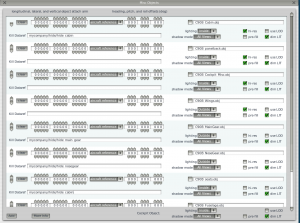
For generic instruments, there are multiple lighting modes that let you pick whether dynamic exposure is applied. The naming convention is a little bit odd:
- Instruments with “auto” do not have dynamic exposure. The idea is that the instrument simulates a photo cell automatically turning up the brightness of the instrument during the day. The instrument is “automatic” – the user does not have to turn up the brightness to compensate for dynamic exposure.
- Instruments with “manual” do have dynamic exposure. The instrument’s simulated brightness is constant, and thus it looks less bright when the sun is out. The user will have to manually adjust the brightness as the time of day changes.
The 2-d panel spills (-2, -3, -4) are always subject to dynamic exposure.
Dynamic Exposure and the Panel Texture
When you use a panel texture in a 3-d cockpit, dynamic exposure is not re-applied to the panel – instead, you get the same dynamic exposure effects that you would get if the panel texture were used directly as a 2-d panel.
Dynamic Exposure and ATTR_lit_level
Dynamic exposure works after ATTR_lit_level directives in an OBJect. During the day, ATTR_lit_level with a value of 1.0 will not be the full texture brightness for objects subject to dynamic exposure.
Some of the datarefs often used for brightness now come in two variants in X-Plane 10: variants for automatic exposure and variants for manual exposure.
sim/cockpit2/electrical/panel_brightness_ratio
sim/cockpit2/electrical/panel_brightness_ratio_auto
sim/cockpit2/electrical/panel_brightness_ratio_manual
sim/cockpit2/electrical/instrument_brightness_ratio
sim/cockpit2/electrical/instrument_brightness_ratio_auto
sim/cockpit2/electrical/instrument_brightness_ratio_manual
sim/cockpit2/electrical/instrument_brightness_ratio
sim/cockpit2/electrical/instrument_brightness_ratio_auto
sim/cockpit2/electrical/instrument_brightness_ratio_manual
The “auto” datarefs automatically compensate for dynamic exposure, and thus match the “auto” brightness settings on generic instruments and are easily visible during the day. The manual brightness ratios do not compensate and will appear dimmer. The non-labeled datarefs are from v9 and provide “auto” behavior for compatibility.
“Auto” datarefs may have light levels larger than 1.0 during the day; this is normal.
Named Lights
A named light is a light, off-the-shelf, that comes fully pre-configured. You specify the name of the light and where it goes and you get a fully built billboard – the sim decides EVERYTHING about it. They’re good for lights that have ‘standard’ meaning in aviation. For example, ‘taxi_b’ is the official name for a blue taxilight, and we all know what one of those is. So
LIGHT_NAMED taxi_b 0 2 0
Where 0,2,0 are the XYZ coordinates of the light and there you go — a light in your model.
All of the major 3-d editor export plugins have a way to add named lights. Typically you add a lamp and tag it with the name that defines the look of the light. The 3-d editor fills in the X,Y,Z coordinates from your 3-d model.
Named lights can create two effects:
- Billboards. A billboard is the picture of a light that always faces the camera. Billboards are typically attached to the light at its source and make the light appear bright. We have had billboards in X-Plane since X-Plane 6 and earlier.
- Spill. A spill light is a light that lights up the surrounding scenery and airplane. The landing light of the user’s airplane has always been a spill light; with X-Plane 10 and HDR you can now add large numbers of spill lights to scenery and airplanes

This picture of the Kingair C90B illustrates billboards and spill. The billboards in this picture have had their texture areas marked with green squares. As you can see, the 4 PAPIs, the nav lights, and the landing lights all have billboards attached.
The landing light is also casting spill on the runway; the spill area has been circled in purple to show the area of its effect. If this Kingair were to park in front of a building, the spill would light up the building.
Most named lights create billboards; some create spills, and some create both a billboard and a spill. The main point to note here is that billboards and spills are created by adding named lights to your OBJs. Because named lights can be put into objects, you can add lights to airplanes or scenery.
Parameterized Lights: Named Lights on Steroids
The only problem with named lights is that you can’t customize them at all – you just say where they go. You can pull a few tricks via OBJs – ATTR_hide will hide a light (now you have on-off) and ANIM_rotate will change the direction it points if it’s directional. But you can’t change the color, the size, or any other properties.
To fix this, X-Plane provides parameterized lights.
LIGHT_PARAM <name> <x,y,z> <more stuff!>
Unlike the named light, the parameterized light can have more input numbers than just the XYZ position. XYZ is always first, but then there are more parameters.
Here’s the tricky thing: the number and meaning of the additional parameters depend on the name of the parameterized light. Each parameterized light has different parameters. Thus each light is customized in a way that makes sense for that light.
To use parameterized lights, you need a table that documents the parameters for each light. A parameterized lighting giude exists for aircraft lights here.
Typically in 3-d programs, you must specify the name and parameters of a parameterized light, but the location is filled in by the 3-d program.
This document describes the parameterized lights available in OBJ files for the use on aircraft. Please first read “Billboard and spill lights for objects” if you are unfamiliar with the concept of billboard and spill lights, or named and parameterized lights in an OBJ file.
This document lists only the parameters for a given parameterized light, e.g. if the document lists:
happy_light <red> <green> <blue>
you would actually have
LIGHT_PARAM happy_light <x> <y> <z> <red> <green> <blue>
in your OBJ file. Most 3-d programs only require you to enter the name and params, so that is what is listed.
General Conventions for Aircraft
X-Plane supports the following types of external lights:
- Landing lights – used to provide runway illumination and visibility to other traffic in the air. They are very bright!
- Taxi lights – used to light up the ground in front of the aircraft while taxiing. Often the taxi light steers with the nose gear to illuminate the ground in front of them.
- Generic lights – these are bright external lights that can be used for any purpose. (They are ‘generic’ – you pick their use.) Typical uses would include: leading edge lights, tail logo lights, engine inlet lights, etc.
- Anti-collision strobes – these are bright strobes, typically on the wing tip used to make the aircraft visible to other traffic in flight.
- Rotating/strobing beacons – these are red beacons on the top and bottom of the aircraft, typically turned on when the engines are on. Some planes use rotating beacons, while others use strobing beacons. X-Plane provides different light types for each.
- Navigation lights – these are small lights: red for the left wing, green for the right wing, and white for the tail, that allow pilots to tell the direction and orientation of another plane in flight. (“Red on right, dead on sight”, because a red light on the right means the plane is headed directly toward the viewer.)
X-Plane supports the following internal lights for the cockpit:
- “Panel” lights, meant to simulate a flood, post, or some other exterior light source that illuminates part of the cabin. Map lights and flood lights fall under this category.
- Instrument lights – these control the brightness of specific instruments. Authors sometimes use instrument lights to control the brightness of back-lit text on an overhead panel, or even to simulate post lights.
For exterior lights, X-Plane always provides separate billboard and spill parameterized lights. Use one of each to create the complete lighting effect. Having the billboard and spill separate allows you to:
- Use two billboards for one spill to make a light ‘cluster’. Overlapping spills can hurt frame-rate, so it is best to use one large spill, not several small ones. For example, an airliner with two bulbs in the wing-mounted landing light would be a good candidate for two billboards, one spill.
- Use a spill without any billboard. For example, a billboard might not be desirable for a light where the actual bulb is recessed.
By convention, spill lights usually end in the suffix _sp.
For interior lights, only spills are provided; at this time we recommend not using billboards on the inside of the aircraft. (Use a _LIT texture to create the lighting of the light source itself. Under most viewing conditions, the user will not be able to see the interior from far away enough to justify a billboard light.)
Systems and Visualization
X-Plane’s lighting is broken into two pieces: a systems model that calculates how bright the light is, and a set of parameterized lights that you attach to a model to ‘see’ those lights on your aircraft. The brightness of the light is affected by the output of the systems.
The systems data can be used to drive LIT textures via ATTR_light_level (or even animations), as well as the parameterized lights. The systems data can also sometimes be customized via a plugin.
Systems Modeling and Aircraft
X-Plane provides a fixed number of simulated lights; however, you can attach as many (or few) lights to your OBJs as you want.
In many cases, the X-Plane systems simulation models more than one of a given type of light. For example, X-Plane supports up to 16 independent landing light simulations in its systems model.
The purpose of these separate ‘systems’ is to allow individual lights to be turned on and off. For example, any of the 16 simulated landing lights can be on or off, drawing electricity or not.
However, it is critical to understand that you, as the modeler and artist of your aircraft, can tie any light billboard to any system. The systems are a simulation, but the OBJ lights are a way to visualize it. So all of these configurations are legal:
- A Cessna has one landing light on the wing, created with a single pair of parameterized spill and billboard, tied to systems landing light index zero. The user has one switch on the panel.
- A Kingair has two landing lights (one on each wing), created with two pairs of spill/billboards. The left wing is tied to system landing light 0, and the right wing is tied to system landing light 1. There are two switches on the panel (one for system 0, one for system 1) and the lights can be turned off and on independently.
- A Baron has two landing lights (one on each wing), created with two pairs of spill/billboards. All of the lights are tied to system 0. There is only a single switch on the panel that turns off and on all lights.
- A 747 has four landing light spills and eight billboards – each “light” on the wing has two billboards to create a particular billboard shape, but only a single spill. Each cluster (two billboards, one spill) is tied to a different system, numbered 0-3. There are four switches on the panel. Thus each of the four switches turns on two billboards and one spill. The user experiences independent landing lights; the paired billboards create a particular ‘wide’ halo effect.
The key point here is that one systems simulation of a light can be tied to one or more parameterized lights. This is accomplished by specifying (in the parameterized lights) which system it is “listening” to.
The same principle applies to strobe lights; all of these configurations work well.
- The author does not customize X-Plane’s strobe light behavior; the aircraft has four strobe lights (two on each wing tip), each listening to the systems simulation strobe index 0. All four strobes light up at once. (This configuration is: one system, four lights.)
- The author has written a plugin to customize the strobe sequence; strobe index 1 fires after strobe index 0. The two forward strobes (left and right) listen to system index 0, the two rear ones listen to index 1. The plugin can thus fire strobe index 0 and then 1 with a data ref for a forward-to-aft strobe order. Since the left and right strobes listen to the same system, the plugin can only turn off the strobes as a whole. (This configuration is: two systems, four lights.)
- The author has written a plugin to customize the strobe sequence: all four strobes are using different system indices. The plugin sets strobes 0 and 1 on at the same time, then 2 and 3 after them. The plugin can fire only strobes 1 and 3 to ‘fail’ the left wing strobes but keep the right wing strobes turned on. (This configuration is: four systems, four lights.)
Systems are always numbered starting at 0. X-Plane currently provides:
- Up to 16 landing lights.
- One taxi light.
- One spot light.
- Up to 64 generic lights.
- Up to 4 independent strobes.
- Up to 4 independent beacons.
Directionality of Lights
A spill light can cast light omnidirectional (a sphere lighting all directions) or in a directional cone. When a spill light is directional, a direction vectors specifies where the center of the cone points to. The direction vector should be a ratio such that the length of the vector is 1.0.
The axes correspond to the coordinate system of an OBJ file. If your OBJ is attached to your aircraft with no rotations, then the positive X axis points to the right wing, the positive Y axis points up, and the positive Z axis points to the tail.
A billboard light is drawn as a square facing the camera; directionality is simulated by making the light dimmer or smaller depending on the angle of the light to the viewer. For example, a landing light billboard that “faces forward” will be brightest when the airplane is viewed head on; the light may be dimmer when viewed from the side, and the billboard will completely disappear when viewed from behind. The direction vector in this case represents the direction from which the billboard is largest/brightest. (If the direction vector faces forward, e.g. 0,0,-1 then you must face the nose of the plane to see the billboard. Thus the direction vector of the billboard and spill should be roughly the same.)
Some lights do not have direction vectors in their parameters; when this is the case, the light (if directional) will face forward, as if its direction vector was 0,0,-1.
All lights are modified by OBJ animation, so one way to modify the direction of the light is to put it inside an animation and use a rotation. Thus you can use an OBJ animation to ‘aim’ a light that does not have parameters for direction.
Spill Lights on Airplanes and Lighting Groups
Objects attached to airplanes in Plane-Maker have a number of properties – see this document for detailed information. In particular, Plane-Maker objects can be in any of three lighting groups: interior, exterior, and glass.
The object’s lighting group affects both which global lights receive light from the airplane and from the world and which other objects the attached spill lights send light to.
In particular, “interior” objects are only lit by spill lights from other “interior” objects and the interior spill lights in Plane-Maker. “Exterior” objects are only lit by other “exterior” objects, the Plane-Maker exterior lights, and scenery lights.
(The goal of this system is to allow the author to isolate the interior of the airplane from exterior lights – in real life it is unlikely that the apron floods or taxi lights make direct contributions to the interior of the airplane. See this blog post for more info.)
“Glass” objects are not lit by HDR spill lights at all and should not have HDR lights attached to them!
Cone Width for Spill Lights
Spill lights have a ‘width’ or ‘focus’ parameter that specifies the shape of the cone of light cast. Use a value of 1.0 for an omnidirectional light.
For directional cone lights, the width parameter is the cosine of half of the cone. (E.g. the angle from the center of the light cone to the edge.) This table lists some common widths:
Cone angle  Angle From Center    Width
 170        85                   0.08715
 160        80                   0.17364
 140        70                   0.34202
 120        60                   0.50000
 100        50                   0.64278
 90         45                   0.70710
 80         40                   0.76604
 70         35                   0.81915
 60         30                   0.86602
 50         25                   0.90630
 40         20                   0.93969
 30         15                   0.96592
 20         10                   0.98480
 10         5                   0.99619
The width value must be larger than zero; spill lights are thus restricted to a cone of less than 180 degrees.
Cone Width for Billboard Lights
For billboards, the cone width formula is:
width = cos(angle) / (cos(angle) - 1)
Where angle is the angle from dead-on viewing to the edge of the cone where the light is invisible.
When making a billboard directional, the direction vector must be scaled by a factor calculated as:
scale = 1 - width
Thus more-directional billboards will have longer direction vectors and larger negative width numbers.
The following table lists some common widths for billboards:
 Cone    Angle     Width        Scale
 Angle    from
         center
 360     180    0.50000        0.50000
 340     170    0.49617        0.50383
 320     160    0.48445        0.51555
 300     150    0.46410        0.53590
 280     140    0.43376        0.56624
 260     130    0.39128        0.60872
 240     120    0.33333        0.66667
 220     110    0.25485        0.74515
 200     100    0.14796        0.85204
 180     90    -0.00000        1.00000
 170     85    -0.09548        1.09548
 160     80    -0.21014        1.21014
 140     70    -0.51980        1.51980
 120     60    -1.00000        2.00000
 100     50    -1.79945        2.79945
 90      45    -2.41421        3.41421
 80      40    -3.27432        4.27432
 70      35    -4.52951        5.52951
 60      30    -6.46410        7.46410
 50      25    -9.67325       10.67325
 40      20   -15.58172       16.58172
 30      15   -28.34774       29.34774
 20      10   -64.82305       65.82305
 10      5   -261.79124      262.79124
 5       2.5 -1049.66472    1050.66472
Note that the width 0.5, scale 0.5 does not make an omnidirectional light: it makes a directional light that just becomes invisible when viewed from behind. To get a truly omnidirectional light, use a direction vector of 0,0,0 and a width of 1.0.
Standard Units for Parameterized Lights
Parameterized lights use numeric parameters to customize the look of the light. The units of those parameters are consistent and often standardized among all of the aircraft lights.
RGB colors: RGB colors are represented as ratios from 0.0 to 1.0. So white is 1,1,1, red is 1,0,0 and a dark blue might be 0,0,0.3.
Systems Index: lights often take an index number for which light in the systems model they track. These indices start at 0 for the first system, and match the indices in data refs. For example, a light controlled with sim/cockpit2/switches/landing_lights_switch[2] should use 2 as its index in the named lights.
Billboard size: billboard size is an arbitrary number – it does not correspond to a physical unit like meters. You will have to experiment to find appropriate sizes.
Spill sizes: the size of a spill is the distance in meters that the spill throws light until it is completely dark. Because the ‘edge’ of the spill light has very low light levels, your size will have to be larger than the size of the spill you want on the ground by some extra factor.
Performance Tip: keep spills as small as possible; the cost in fps of a spill light is a function of the area it covers. So a very large (but dim) spill light uses more GPU power than a small bright one.
Cone Withs: directionality of spills is referred to as “width” or “w” and follows the first table above; directionality of billboards is referred to as “focus”; if a billboard has directionality but no direction vector, use the “width” value from the table but ignore the “scale” value.
Related DataRefs: Each set of lights lists two datarefs: the dataref used to turn the light on/off (in sim/cockpit2) and the light that reflects the current light brightness, which can be used for ATTR_light_level.
List of Named Lights
Each light is listed with its parameters in order. All parameterized lights have an XYZ location before the light-specific parameters.
Landing, Taxi, Spot and Generic Lights
The landing, taxi, spot and generic lights all have the same composition, and are listed together. They differ only in what systems they reference, and in the texture of their billboards.
airplane_landing_core      X    Y    Z    INDEX    SIZE
airplane_landing_glow      X    Y    Z    INDEX    SIZE
airplane_landing_flare     X    Y    Z    INDEX    SIZE
airplane_landing_sp        R    G    B    INDEX    SIZE    W
Switch Dataref: sim/cockpit2/switches/landing_lights_switch[INDEX]
Brightness: sim/flightmodel2/lights/landing_lights_brightness_ratio[INDEX]
airplane_taxi_core      X    Y    Z    INDEX
airplane_taxi_glow      X    Y    Z    INDEX    SIZE
airplane_taxi_flare     X    Y    Z    INDEX    SIZE
airplane_taxi_sp        R    G    B    INDEX    SIZE    W
Switch dataref: sim/cockpit2/switches/taxi_light_on
Brightness: sim/flightmodel2/lights/taxi_lights_brightness_ratio[INDEX]
airplane_spot_core      X    Y    Z    INDEX    SIZE
airplane_spot_glow      X    Y    Z    INDEX    SIZE
airplane_spot_flare     X    Y    Z    INDEX    SIZE
airplane_spot_sp        R    G    B    INDEX    SIZE    W
Switch data ref: sim/cockpit2/switches/spot_light_on
Brightness: sim/flightmodel2/lights/spot_lights_brightness_ratio[INDEX]
airplane_generic_core      X    Y    Z    INDEX    SIZE
airplane_generic_glow      X    Y    Z    INDEX    SIZE
airplane_generic_flare     X    Y    Z    INDEX    SIZE
airplane_generic_sp        R    G    B    INDEX    SIZE    W
Switch Dataref: sim/cockpit2/switches/generic_lights_switch[INDEX]
Brightness: sim/flightmodel2/lights/generic_lights_brightness_ratio[INDEX]
X, Y, Z: Billboards take a direction vector that defines the direction in which the billboard is brightest. The length of the XYZ vector defines the level of directionality; see the “scale” table above for how to make a longer vector for a more directional light.
R, G, B: Each spill light takes an R,G,B color that is used to tint both the spill.
INDEX: this is the index into the systems data-ref array that the light uses to calculate its brightness.
SIZE: the size of the billboard or spill. Spill is in meters, billboards are in arbitrary units.
W (width): spill-only the width of the light cone. The cone width for the billboards is pre-determined.
airplane_XXX_core – a small billboard that represents the bulb itself.
airplane_XXX_glow – A larger ambient glow billboard that represents the illumination of moisture around the light.
airplane_XXX_flare – A very large star-shaped billboard pattern that appears when looking _directly_ at the light.
airplane_XXX_sp – a spill light to cast a light cone.
The taxi and spot light datarefs are ints – they are on or off. The landing and generic light switches are floating point – you can set landing lights to half-power by setting this to 0.5.
All brightness datarefs are floating points; as the taxi light comes on, for example, it will ‘ramp up’ from 0.0 to 1.0 in brightness over a second or two.
Beacons
There are separate lights for rotating beacons vs. strobing beacons.
airplane_beacon_rotate       PERIOD    PHASE
airplane_beacon_rotate_sp    PERIOD    PHASE    SIZE    WIDTH
A rotating beacon – the first light is the billboard, the second is the spill.
PERIOD: the period in which the beacon makes a full rotation. So 2.0 means the beacon rotates once every 2 seconds; 0.5 means it rotates twice per second.
PHASE: the phase offset of the beacon as a ratio (0.5 means 180 degrees out of phase). Use this to create multiple beacons that don’t all face the user at the same time.
SIZE: spill-only, the size of the spill cast by the rotating beacon, in meters.
WIDTH: spill-only, the width of the cone – see the above table for spill widths.
airplane_beacon_strobe       SIZE    INDEX
airplane_beacon_strobe_sp    SIZE    INDEX
A strobing beacon – it flashes when the systems model says the beacon is ‘on’. SIZE: the size of the billboard and spill.
INDEX: the index into the beacon data ref that the beacon tracks.
Switch data ref: sim/cockpit2/switches/beacon_on
Brightness: sim/flightmodel2/lights/beacon_brightness_ratio[INDEX]
Anti-Collision Strobes
The anti-collision strobes have two billboard definitions: one for billboards visible from all angles and one for billboards only visible from some angles.
airplane_strobe_omni  I1 I2 I3 INDEX    SIZE
airplane_strobe_dir   X1 Y1 Z1 INDEX    SIZE    X2   Y2   Z2   W2
airplane_strobe_sp    R G B    INDEX    SIZE    X    Y    Z    W
I1, I2, I3: these are ignored; please set them to zero.
Index: the index of the strobe data ref that the light tracks.
Size: the size of the billboard or spill.
X1, Y1, Z1: for a directional billboard strobe, this direction vector fades out the strobe (with translucency) – the magnitude of X1,Y1,Z1 forms the focus of the effect. Recommendation: do not use faded strobes – set these to 0,0,0!
X2,Y2,Z2, W2: for directional billboards, this fades out the term; W2 sets how much of the strobe is visible at any direction and should be set to 1 – length(x2,y2,z2).
R, G, B: for spills, the color of the spill.
X, Y, Z: for spills, the direction of the spill – this should be normalized.
W: for spills: the cone angle of the strobe (use 1.0 for omnidirectional spills.)
Switch dataref: sim/cockpit2/switches/strobe_lights_on
Brightness: sim/flightmodel2/lights/strobe_brightness_ratio[INDEX]
sim/flightmodel2/lights/strobe_flash_now (goes to 1 if any strobe is flashing)
Navigation Positional Lights
airplane_nav_tail_size   SIZE    FOCUS
airplane_nav_left_size   SIZE    FOCUS
airplane_nav_right_size  SIZE    FOCUS
airplane_nav_sp          R G B    INDEX    SIZE    X    Y    Z    W
Billboards: size is the size of the billboard; focus is the ratio that describes how visible the light is off-angle from the table above. The billboards are already colored red, green and white – pick the billboard name that matches the position light you want.
Spill: RGB tints the spill light – there is one spill light for all navigation positions.
Index: this is ignore and should always be set to 0.
Size: the size of the spill in meters.
XYZ: the direction the light points – use 0,0,0 for omni-lights.
W: the width of the light cone from the table above, or 1.0 for an omnidirectional light.
Switch dataref: sim/cockpit2/switches/navigation_lights_on
Brightness: sim/flightmodel2/lights/nav_lights_brightness_ratio[0]
Internal Cockpit Spill Lights
Two parameterized lights provide spill lighting inside the cockpit that follows the panel and instrument light datarefs.
airplane_panel_sp R G B INDEX SIZE X Y Z W
Switch dataref: sim/cockpit2/switches/panel_brightness_ratio[INDEX]
Brightness:
sim/cockpit2/electrical/panel_brightness_ratio_auto[INDEX]
sim/cockpit2/electrical/panel_brightness_ratio_manual[INDEX]
airplane_inst_sp R G B INDEX SIZE X Y Z W
Switch dataref: sim/cockpit2/switches/instrument_brightness_ratio[INDEX]
Brightness:
sim/cockpit2/electrical/instrument_brightness_ratio_auto[INDEX]
sim/cockpit2/electrical/instrument_brightness_ratio_manual[INDEX]
Use airplane_panel_sp to tie a spill light to the flood/panel light datarefs; use airplane_inst_sp to tie a spill light to the instrument light data refs.
RGB: the color of the light.
INDEX: the index into the dataref to set the brightness.
SIZE: the size of the light in meters.
XYZ: the direction the light faces, or 0,0,0 for omnidirectional
W: the width of the light cone from the table above or 1.0 for omnidirectional lights.
Auto vs. manual: in aircraft cockpits, some instruments will contain a light sensor that automatically adjusts the display brightness of the instrument to match the ambient lighting. For example, a Bendix King radio stack will turn the brightness of the radio LEDs up during the day (so that they are readable in full sunlight) and down at night (so that they are not annoyingly bright during bright flight.
X-Plane provides two versions of the cockpit/panel brightness levels in two sets of datarefs.
- The _manual datarefs simulate a light that stays the same brightness under all conditions. Such a light will typically be either too dim during the day or annoyingly bright at night if the user does not manually adjust it. (The dataref is named _manual because a pilot must _manually_ adjust it for comfort.) This datare’fs value will stay constant during all times of day.
- The _auto datarefs simulate a light that is tied to a photo-cell and automatically becomes brighter during the day. Lighting that follows this dataref will appear ‘bright and readable’ during the day and night without user intervention. If you change the time of day you will see this dataref take on very large values during the day (as the photo-cell indicates more light is needed) and then go back down to normal values at night.
This document lists changes that you may need to make to update an aircraft from X-Plane 9.70 to X-Plane 10.10. Some items are optional, and some items are just checks; where possible Plane-Maker tries to update your airplane with good default settings for new features.
Make Sure Glass Is Glass
For X-Plane to render your airplane correctly with HDR enabled, the sim must know which of your objects are translucent.
- Make sure that any attached object with translucency is marked as “glass” in the Plane-Maker attached object screen.
- Separate your solid objects from glass ones to isolate translucent surfaces.
- In X-Plane 10.10 you can use the panel texture from any object. So if you have translucent surfaces and opaque surfaces in the panel texture, use the panel texture in two objects.
The draw order of objects is:
- cockpit object (external views only) if it is not glass.
- Internal and external objects, in the order of the Plane-Maker screen.
- cockpit object (internal views only) if it is not glass.
- cockpit object (if it is glass).
- Glass objects, in the order of the Plane-Maker screen.
Use Power-of-2 Panels for the 3-d Cockpit
Make sure your panel texture is a power of 2 in dimensions (or uses regions). Then add GLOBAL_cockpit_lit to cockpit objects so that the HDR lighting engine can work on the panel texture too.
If you use the panel texture in more than one object (see above) add GLOBAL_cockpit_lit to every object that uses the panel texture.
You do not need to use GLOBAL_cockpit_lit if you already use panel regions and you do not need translucency in your panel texture. You should use GLOBAL_cockpit_lit if you use translucent panel textures using ATTR_cockpit.
Resize Internal Spill Lights
Plane-Maker provides 3 internal spill lights, visible with and without HDR enabled. The intensity of light they emit is a little bit different in X-Plane 10.10, relative to X-Plane 9. You may have to make the lights larger or smaller – the change needed is airplane specific.
Mark Attached Objects as “Dim LIT” as Needed
Dim LIT is a new option that reduces the brightness of lit textures during the day. For scenery this effect is automatic, but for airplanes you must “opt in”.
- Do set “Dim LIT” for exterior render-baked textures. For example, this option will let you bake night lighting that is vivid at night but not overpowering during the day.
- Do not set “Dim LIT” for interior lighting that is visible during the day. For example, if you create landing gear indicator lights using a LIT texture (and animation) you would not want to “Dim LIT” them because that would make the gear indication difficult to see during the day.
Update Exterior Lights
The exterior lights tab in Plane-Maker is significantly enhanced for X-Plane 10; while Plane-Maker attempts to update your exterior lights for you, you may find that you can get better results by customizing your lights.
Pre-fill is an object setting that tells Plane-Maker to “block” the clouds using that object. Setting prefill:
- Can improve framerate a lot. For example, if you enable pre-fill on the object that represents your cockpit shell, you will mask out a lot of clouds.
- Causes the object to be drawn twice, so it’s a better choice for simple objects than for objects that have heavy animation.
- Should not be used with translucent objects.
For users who are limited by fill rate, prefill can be a 2x optimization on some planes (e.g. it doubles the user’s framerate).
Adjust Starter Parameters
X-Plane 10.10 features an optional RPM limit on the starter; check how your airplane starts and adjust the new settings as needed. You may find that your v9 defaults are still acceptable.
Disable Some Starter Check-Boxes in Plane-Maker
X-Plane 10 will automatically enable a number of behaviors with your starter when opening an X-Plane 9 airplane; you may need to disable them.
- Disable the option “hitting starter engages fuel to engine” if your airplane has manual mixture/fuel-cutoff controls.
- Disable the options “hitting starter arms igniters” and “hitting starter engages igniters” if your airplane has manual igniter controls.
- Disable the option “hitting starter engages ignition” only if you have a reciprocating engine with separate magneto and starter controls (e.g. an airplane with push-button start). For key-lock-style starters like in a Cessna 172, leave this checked!
Check Minimum N2
X-Plane 10.10 provides a minimum N2 for fuel introduction in the engine spoolup/boost page. While Plane-Maker will try to initialize this from your airplane’s old data, you should check the value of this field – it affects the EGT of your engine during startup and cruise!
Check all Electrical System Settings
Check the electrical system bus assignments and amperages in the bus 1/bus 2 screens of the systems dialog box in Plane-Maker. X-Plane 10 has had a number of bugs importing this data, so we recommend double-checking this data in X-Plane 10.10 final to confirm that it is correct.