These lighting techniques apply to both 2-d panels and 3-d cockpits that use 2-d panels as textures.
Instrument Overlay Lighting Modes
Generic instruments overlays have one of three lighting modes – the lighting mode controls how LIT layers are used and how the instrument reacts to brightness changes. In considering the mode, each instrument has:
A power source.
A rheostat controlling instrument brightness.
Some amount of light falling on the instrument, the sum of ambient, flood, and spot lights.
Built-in instruments typically have either the glass or mechanical mode, but a few are composed of parts that have both properties.
Mechanical Lighting
Mechanical lighting is the simplest mode: the overlays brightness comes from the sum of ambient, flood and spot lighting hitting the instrument overlay. This mode of lighting is appropriate for instrument overlays that simulate mechanical parts, parts that require something to cast light to be seen.
If electric power fails, the instrument is still drawn; the power failure is noticeable because the spot and floods will go dark, reducing the amount of light that falls on the overlay.
For backward compatibility, mechanical lighting will use the _LIT texture when it is dark and the electrical system is on. However, we recommend that you use back-lit lighting for mechanical lit instruments in X-Plane versions 920 and newer. (See below.)
You can cause mechanical lit instruments to disappear using generic instrument filters; this might be appropriate for a mechanical flag, for example.
Glass Lighting
With glass lighting, the instrument brightness rheostat determines the brightness of the instrument. The light cast on the instrument has no effect. This is appropriate for EFIS elements and other “glass” displays. If power fails, the instrument is not drawn at all.
For backward compatibility, mechanical lighting will use the _LIT texture when it is dark and the electrical system is on. However, we recommend that you use not use this feature with glass lighting in X-Plane versions after 920. (See below.)
Back-Lit/Additive Lighting
Back-Lit lighting is a new lighting mode: the daytime texture is drawn based on the sum of ambient, spot and flood lighting; the LIT layer is then added on top of the day time texture (when power is available) at a brightness based on the instrument rheostat.
The result is an instrument that is self-lighting, but still visible due to ambient light if power fails.
Lighting Modes for Non-Generic Instruments
You can set the lighting rheostat property on any instrument, even an old one.
The parts of that instrument that respond to the “instrument brightness” rheostat will now follow any of the 16 lighting values.
This lets you use the moving map and pre-made EFIS elements with multiple lighting rheostats.
In X-Plane 930 and newer, you can set the legacy lighting mode to “mechanical” or “additive” (which corresponds to mechanical or back-lit for generics). Legacy instruments are “glass” or not based on their type, and in fact some parts may be glass while others are not.
Lighting for 2-D Panels Only
Theoretical Model
Under the new 2-d panel lighting model, there are four sources of light:
Ambient light comes from outside the plane – its level is a rough approximation of sun and moon effects (but in the 2-d panel it is not directional.)
The flood light fills the entire panel with a single color, similar to what was available in 902. The flood level is controlled by the panel brightness rheostat (flood light rheostat).
Up to 3 spot lights fill some areas of the panel with a specific color. The spot lights are defined by an RGB color in PlaneMaker and a mask (indicating where they have influence) in a PNG file. Three new rheostats control the spot light brightness individually.
Instrument overlays can also have “emissive” lighting – that is, they can light themselves up regardless of these other effects. Instrument brightness can come from one of sixteen rheostats; default instruments use rheostats 0 and 1 (for pilot and copilot). Old datarefs and instruments keep rheostats 0 and 1 in sync for compatibility with 902 and beyond.
Panel Background Spot Light and Shadow Masks
Four things are necessary to use the new panel spot-light feature:
Include at least one spot light overlay. These overlays have the same name as the panel, with the extensions -2.png, -3.png and -4.png. Their format is a gray-scale PNG (no alpha) of the same size as the main panel. These correspond to each of the three spot-lights.
Change the -1 shadow layer from RGB+alpha to gray-scale, no alpha. In its converted form, white means more shadow, black means no shadow.
Set the RGB colors for the three spot lights in the PlaneMaker view screen (lights sub-tab).
Optional: include rheostats to control the spot light levels.
The change in shadow format is very important: without the spot light system, the shadow uses transparency to overlay a color image. With the shadow format, the shadow is a simple gray-scale mask, with higher values meaning more shadow.
Spot lights affect burned-in instruments on a per-pixel basis; that is, the the spot light masks combine with the background image to produce a lighting effect.
Spot lights affect overlays on a per-instrument basis; that is, the overlays will take on a lighting level from the average of the spot light around the instrument, but one side of an overlay can’t have a different spot-light affect from the other side. The precise way spot lighting is used depends on the lighting mode (see below).
Lighting Tips
Creating Glow Effects With Default Instruments
In X-Plane 930 and newer you can use “additive” lighting with the default instruments – set the lighting mode to “additive” in Plane-Maker and add _LIT-1, _LIT-2 textures etc. to the overlays.
This effect is typically used to make LEDs and back-lit numbers have a warm “glow” at night.
There are two problems with this technique. First, additive lighting can only be used on the overlays of an instrument, e.g. the -1, -2, -3 and -4 layers. So there is no way to make the background glow. For example, if an instrument has its numbers and markings in the background, those can’t be made to glow.
The work-around is to make a new instrument, typically a generic rotary with 1 image cell and no click mode, with additive lighting mode and the image of the glow. The glow goes in the -1 layer.
This glow instrument must be lower in the panel “stack” than the instrument you want to glow. The glow will appear on top of the background (since all backgrounds are drawn before any overlays) but under the moving parts of the regular instrument (which is higher in the sack).
For an example of this, see the default C172 in X-Plane 930 or newer. Since the steam gauges have their markings in the background, the author uses a single large generic to add all the glow effects to the six-pack instruments.
The second problem is that default instruments automatically categorize their layers into lit vs. mechanical lighting…the “additive” option only affects those “mechanical” layers. For example, in the radio stack, the LEDs are automatically categorized as “lit”, so additive lighting is not available for them.
Usually this is not a problem – if the layer is lit, you wouldn’t need glow because the lit texture would already contain this.
Per-Pixel vs. Per-Vertex Limitations
The 2-d “lighting” masks (-2, -3, and -4 layers on the panel background) add light to the panel and instrument background and any burned in elements on a per-pixel basis.
However, due to performance limitations, these effects only affect overlays on a per-vertex basis. That is, the entire overlay is lit uniformly by the -2,-3, or -4 mask based on one sampling point. (The same is true for the -1 shadow layer.)
There is no one good work-around for this…typically you will have to use a combination of careful shaping of the background lighting effects and possible use of lighting overlays to reduce artifacts.
Everybody always asks, and few ever understand, how the propeller beta and reverse models work in X-Plane.
Everything here applies to single and multi-engine propeller planes in X-Plane, and also applies to REAL KingAirs and Lancair Evolutions and the like (planes with PT-6 engines) because they work mostly the same way. To simulate non-PT-6 airplanes, use the info in this document to see how X-Plane works, and then tweak the inputs into Plane-Maker as needed to suit your propeller-driving engine.
So let’s start with the REAL airplane description, and then move on to entering data into Plane-Maker after that.
Real Airplanes
The Red Knob: the Condition Lever
If this is all the way forward, then you are at FLIGHT idle. This dumps enough fuel into the engine, even at IDLE throttle, to keep the flame from going out.
If this knob is about halfway back, then you are at GROUND idle. This is a lower idle speed, designed for the taxi-only operations, where a flame-out would not be catastrophic.
If this knob is all the way back, then you are at CUT-OFF: All fuel to the engine is cut, with predictable results.
The Blue Knob: Prop RPM
This knob does not control fuel to the engine, but instead commands the RPM that the prop WANTS to turn.
If the prop is turning SLOWER than the RPM commanded by the blue knob, then the prop will FLATTEN.
If the prop is turning FASTER than the RPM commanded by the blue knob, then the prop will INCREASE its pitch to slow down.
As long as there is enough power and/or airspeed through the prop disc, then the RPM that you have commanded with the blue knob will be followed by the prop.
Now, if the blue knob is all the way FORWARD, then the prop will adjust pitch to try to hold REDLINE RPM (maximum rpm for take-off or fast cruise). As you drag the blue knob AFT, you get progressively less and less commanded RPM, until you get the blue knob all the way aft, at which point the prop will FEATHER (if this is a feather-able prop–some are, some aren’t), where it goes to the feathered pitch of the prop, which will result in basically zero rpm.
The Black Knob: Throttle
And now, finally, the BLACK KNOB, which we commonly refer to as the ‘throttle’, but will also control the prop in certain cases, as we will show below.
When you are doing regular flying, you have the throttle at or forward of the idle stop. As long as the throttle is at or forwards of the idle stop, the propeller is in what is called ALPHA mode.
In ALPHA MODE, the propeller acts as described above, adjusting pitch to try to hold the RPM commanded by the blue knob (redline when all the way forward, minimum or feathered when all the way back). This means that it tries to hold the RPM commanded by the BLUE KNOB, and it does this by adjusting prop pitch as needed to hold that commanded RPM. This is how you taxi and fly.
Now, sometimes, as you taxi in a PT-6 turboprop, your taxi speed starts to build up too high for comfort even with the engine at IDLE!
This, perhaps, is not surprising when you have an engine of about 1,000 horsepower on a light airplane, and being a turbine, it even idles fast to keep the desired airflow running through the engine. (This is needed, interestingly, to keep the engine from overheating! If a PT-6 were to idle too slowly, then the blanket of air that isolates the flame of combustion from the engine wall would deteriorate, allowing the flame to touch the engine wall and melt the engine! So we actually have to idle fast in a PT-6 to keep the combustion flame from reaching the engine wall and destroying it!)
When taxiing, we have a hugely powerful engine running at a high idle, so even at ground idle, the taxi speed might be too fast for comfort.
In that case, you lift the black knob aft of the idle stop and drag it back.
As you do so, the engine stays at idle, and the farther you drag the handle aft, the more the prop pitch moves from flat pitch to beta pitch. This is beta.
If you keep moving the throttle back even FARTHER, then the prop pitch moves from BETA pitch to REVERSE pitch, and the throttle starts coming up as well! This is reverse.
NOTE: Beta and reverse only work if the blue knob is all the way forwards. For whatever reason, Pratt and Whitney just designed the system this way.
Here is a table diagram:
(NOTE: all transitions between the states should be smooth and continuous. There is no sudden jump anywhere.)
Throttle Position
Prop Mode
Fuel Flow
1
forward
alpha mode
max!
2
idle stop
alpha mode
ground or flight idle
3
beta
beta pitch
ground or flight idle
4
reverse
reverse pitch
full reverse fuel flow
Setting up Plane Maker
Now, on to Plane-Maker, which you can set up to perfectly match the PT-6 described above.
Go to the ENGINE tab in Plane-Maker.
For the critical altitude upper-left, enter the maximum altitude at which that maximum power is actually available.
PT-6’s are typically flat-rated, so you can enter some altitude above 0 here… most PT-6’s continue to give full power as they climb until they hit a temp-limit and then they lose power as they climb above that point. Whatever point you first have to drop below max torque at max RPM due to hitting a temp-limit–that is the critical altitude: The highest you can fly and still get full power.
Below that you see the box for the FADEC. Check it if you have it–some PT-6’s have that, some don’t.
Throttle available at max lever is the throttle available when the throttle is all the way forwards. This is usually 1.00, but if your Ng (called N1 in X-Plane) goes over 100% in the real plane, then enter a slightly higher number here.
Below that, you see your low and high idle adjustments: Simply adjust these ‘idle screws’ up or down a bit as needed to idle at just the right Ng, or torque, when you are at low or high idle.
Now, below that, you see “Go to BETA PITCH below this throttle lever position”. This is the position shown in line 2 in the throttle position map up above.
If you are dragging the throttle with the mouse or have a hardware throttle, then below this value for that device, we start going into BETA.
Now, below that, you see “Go to REVERSE below this throttle lever position”. This is the position shown in line 3 in the throttle position list up above.
If you are dragging the throttle with the mouse or have a hardware throttle, then below this value for that device, we start going into REVERSE, and the throttle starts coming up as well!
Now, below that, you see “throttle available at max reverse lever position”. This is simply the percentage of maximum throttle that is available when you pull the lever all the way back to the aft stop. It is the throttle available from the engine in line 4 above.
Now, here is something interesting: If you want your physical throttle handle to be set up like the throttle in a real KingAir or Evolution or the like, then you will use the values above to scale the throttle accordingly.
But here is where it gets bogus: In the REAL airplane, there is a GATE at the idle stop of the throttle that keeps you from going into beta by mistake: You have to lift a trigger to get over the gate and into beta to keep you from going into beta by mistake in flight. But you probably don’t have that gate on your physical throttle quadrant, or want to mess with trying to find that exact point when moving the throttle, or even operating the throttle with the mouse on the monitor. You probably want to just drag your throttle all the way back to go to idle, since that is the way any normal person would want to descend! So, in Plane-Maker, you could easily enter ZERO for the “Go to BETA PITCH below this throttle lever position” and “Go to REVERSE below this throttle lever position,” so X-Plane NEVER goes into beta or reverse when you drag the throttle all the way aft! This way, you can just slap the throttle back to the aft stop to go to idle. This is the way anyone would want to fly the airplane.
Then, to go into beta, hit the / key. To go into reverse, hit the ? key. (And hit again to toggle out). And, while in reverse, you can run the throttle right back up again to go farther into reverse! This way the ergonomics are not like the real airplane, but you can really control what is going on. If you want the ergonomics to be the same as the real plane, then enter the throttle positions as mentioned above… but you better not drag the throttle all the way back in flight, or you will go into beta and then reverse in flight! The REAL plane has a gate at the idle stop to stop this from happening!
In the main screen at right, for the maximum power box, enter the maximum continuous power allowed by the engine. This is the maximum power allowable at sea level (not maximum thermodynamic, which you would never use or you would wreck your gear-box!).
For the prop pitch numbers, the top is the feathered pitch of the blade, as you get with the blue knob all the way back… maybe 60 degrees.
Then the coarse pitch is the maximum the prop can open up in alpha mode… maybe 45 degrees.
The fine pitch is the flattest the prop can go in alpha mode… maybe 10 degrees.
The beta pitch is the flattest the prop can go in beta mode… maybe 0 degrees.
The reverse pitch is the flattest the prop can go in reverse mode… maybe -45 degrees.
So, that is how a real PT-6 works, and how to set it up in X-Plane.
A color profile describes what the meaning of various RGB color triples mean, that is, how red is red?
It is important that the color profile you author your textures with is the same as the one X-Plane uses to show them.
The recommended color profile is sRGB, a standard color profile. You work in sRGB color space, save your files with this marked on the PNG file, and then X-Plane can adjust the color if the user’s display doesn’t match sRGB.
Steps For Correct Color
To maintain correct color, you must do three things:
Author with correct color
Save your work in a way that will not confuse X-Plane
Set up X-Plane to correctly recreate that work
Setting up the Authoring Environment
In order to create a texture that looks right, you need to author in an environment where ‘red’ is really ‘red’. To do this, you need to:
Set your monitor to an sRGB color profile.
Set your painting program to both work and save using the sRGB color space.
Making Sure Textures Are Saved Properly
Your saved PNG files must contain either a gamma chunk that indicates a gamma of 0.45445 or an sRGB chunk or both. How you do this will depend on your painting tools, but one of these chunks must be present for X-Plane to “know” that your texture is authored in sRGB.
If you are working with DDS, use XGrinder and DDSTool – X-Plane’s handling of color correction with DDS textures is [quirky]; using XGrinder/DDSTool ensures that the DDS file is encoded with the same rules X-Plane will use to decode it.
Setting Up Correct Viewing in X-Plane
Finally, to see how the texture looks in sim, keep your monitor calibrated to sRGB and set X-Plane’s gamma setting to 2.2. This will tell X-Plane that it does not need to modify your textures, which are already in sRGB, just like your monitor.
Mac Users: if you are using a version of OS X before 10.6, your monitor’s gamma will probably be set to 1.8. In this case, you can set X-Plane’s gamma to 1.8, but setting the color profile’s gamma to 2.2 might be a more accurate way to work.
This article describes how to locate a user’s X-Plane 9, 10, or 11 installation – it is targeted at third party add-on vendors who want to make the installation process easier for users.
Important: a user may have more than one copy of X-Plane installed on their computer. While we expect normal users to have only one copy of X-Plane, there is no requirement that there be a single installation.
X-Plane creates a text file in the user’s preferences that lists all known locations of X-Plane. The file is a simple text file with each line being a full path to an X-Plane installation location.
Not every file path points to a valid installation location. If the user has moved X-Plane, then some of the paths may be old and stale. An installer must examine each of the install locations and determine whether the location is in fact a copy of X-Plane. X-Plane’s updater simply validates that the directory exists, but you could also verify the presence of the Resources folder inside the root folder. You cannot assume that any given executable will be in place, as the executable names vary by operating system.
The installation list file is named
x-plane_install_11.txt for X-Plane 11
x-plane_install_10.txt for X-Plane 10
x-plane_install.txt for X-Plane 9.
The location of this file varies by operating system:
OS X – the file will be in the user’s preferences folder, i.e. ~/Library/Preferences/.
Windows – the file will be in the user’s local app data folder, i.e. C:\Users\nnnn\AppData\Local\. Use CSIDL_LOCAL_APPDATA to find the location.
Linux – the file will be in the user’s home folder in a .x-plane/ sub folder, i.e. ~/.x-plane/.
Comments Off on How To Programmatically Locate X-Plane on the Hard Drive
This tutorial will walk through overlaying a photo onto an aircraft fuselage in Plane Maker. It assumes familiarity with the basic aircraft texturing techniques discussed in the Creating Basic Paint Textures tutorial.
You can download the aircraft file and images used in this tutorial here: A36_photo.zip
Selecting a Photo
The ideal photo to use as a Plane Maker texture is one taken from a 90 degree side view with even lighting across the whole of the fuselage. Beyond these requirements, be sure sure your use of the photo complies with the terms of its copyright.
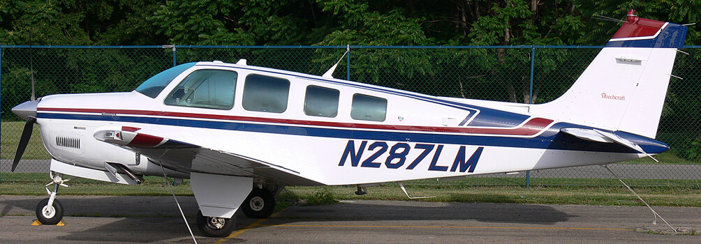
For our example Bonanza, we used the photo below, with many thanks to its copyright holder Terry Shepherd:
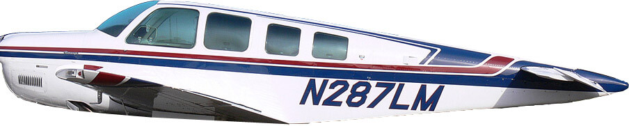
Create a starting point PNG image as in the Creating Basic Paint Textures tutorial. Then, using your image editor, cut away everything from your photo except the fuselage. In Photoshop, you can use the lasso tool to do this. You will inevitably get some of the wings in the photo, but don’t worry about these for now.
In our case, this fuselage-only image looked like this:
The A36 fuselage
This image was stretched and warped (using the Transform options in Photoshop’s Edit menu) to sit over the starting-point image of the fuselage. Note that it is not uncommon to have a large area on the top and bottom of the fuselage side views that is not covered by your stretched image. This area, like the parts covered by the wings, can be cleaned up later.
Go through the same procedure to texture the wings, stabilizers, engine nacelles, and so on. For each piece that you have a photo, you’ll need to:
crop a version of the original image to include nothing but that piece,
paste the image of that piece over its placeholder in the starting-point image, and
stretch and/or warp the piece to fit the area you defined in Plane Maker.
Do this for both the left and right sides of the aircraft, where necessary.
Using a layered image format like PSD will prove invaluable for making small changes during this process.
Because a top view of our example aircraft’s wings and horizontal stabilizers was not available, our example aircraft will only have it fuselage, vertical stabilizer, and engine housing textured with the photo. For the rest of the wings, we will simply use the same solid white that the body is painted with.
Touching Up the Photo
With a rudimentary version of each piece of the aircraft placed properly, it’s time to clean it up. Note that each time you save your Aircraft name_paint.png file, you can press the T key in Plane Maker to reload the texture.
Unless you have photos of the top and bottom of the aircraft, you will probably want to use Photoshop’s clone stamp tool (or an equivalent) to fill in the top and bottom of your fuselage. Because our example Bonanza has a flat underside, there was a great deal of area that needed this in our photo. Because the aircraft has a very plain, flat white texture for most of its body, this wasn’t a problem.
The clone stamp tool should also be used to get rid of the wings and any other bodies that are attached to the fuselage in the photo but are not actually part of the fuselage.
Finally, in addition to cloning for the top and bottom of the fuselage and removing the wings and other non-fuselage bodies, you’ll need to use your image editor to remove the shadows and other artifacts of uneven lighting across the body (because, of course, the X-Plane simulator will add its own shadows where it needs them.
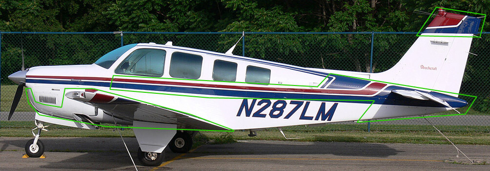
We’ve highlighted the most prominent trouble areas in green in our photo here:
Trouble areas in the Bonanza A36 photo
In the areas highlighted, our aircraft texture needed a lot of attention before it would look convincing in X-Plane.
A Note on Windows
If you are creating a 3-D cockpit object in a program like AC3D or Blender, you will want to completely fill in the windows in this overlay image, as the transparent windows in your cockpit object will replace this texture as needed. Since, for the purpose of this tutorial, we are not creating a 3-D cockpit object, we left the windows and made them semi-transparent.
Examining the Finished Product
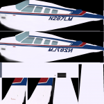
Our finished images are seen below, and are also included in the completed aircraft ZIP. Our ACF file is A36_photo.acf, so our two image textures are A36_photo_paint.png and A36_photo_paint2.png, respectively.
A36_photo_paint2.png
A few things to notice about these images:
The textures for some pieces overrun the area laid out for them by the Plane Maker-generated starting points, but for small areas, this isn’t a big deal.
The white area in the middle of the first texture image is used for the gear doors and struts, which were too shadowed in our image to be usable. Instead, the white texture from the body was copied.
The propeller texture (located in the far left center of the first image) is simply made of a darkened slice of the nacelle texture, which itself is in the second image.
Since our original image was of the left side of the fuselage, the tail number on the right side had to be reversed.
Comments Off on Creating Photo-Real Paint Textures
This tutorial will walk through the creation of a basic paint job for an aircraft file in Plane Maker. It require only Plane Maker (and the image editor of your choice) to do so–it doesn’t make use of any 3-D modelling programs.
This tutorial assumes familiarity with the Plane Maker interface, and it references the aircraft file created from scratch in the basic aircraft creation tutorial.
Introduction
Plane Maker can be used to overlay a 2-D image on a 3-D aircraft model. For this tutorial, we will apply a very simple (and ugly) paint scheme to our example aircraft.
In order to understand how the textures are applied, we will look at the example aircraft found here: Bonanza_A36_painted.zip
Creating a Starting Point
We will begin by setting up the approximate placement of our aircraft’s parts in the image which we will create. From that data, we will have Plane Maker create a PNG file that will serve as our starting point.
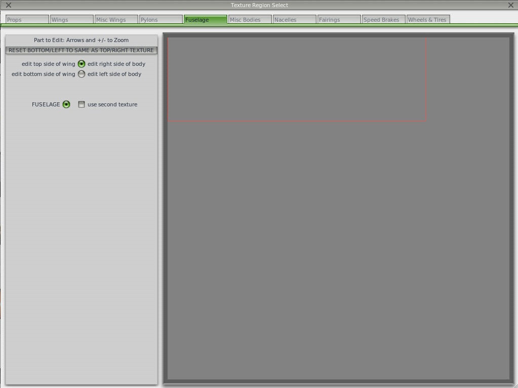
To begin, open the Expert menu in Plane Maker and click Visual Texture Regions. In the window that appears (shown in the image below), you can click and drag the flashing red boxes to change which area of the (currently non-existent) image will be used for each part. Move between each part of the aircraft using the tabs at the top of the window.
Texture Region selection window
For now, don’t worry about modifying the positions of anything but the fuselage, wings, and engine nacelles–these are the parts of that plane that will be in the starting-point image that Plane Maker creates for us. For now, our biggest concern is making sure that none of these parts overlap one another accidentally. Note that you can (but do not have to) use the same area of the image for both the left and the right side of each part. Note also that you can check the use second texture box, which will force X-Plane to look for a second image for that part of the aircraft.
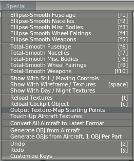
Once you get your aircraft’s parts arranged in roughly the positions you want them, close out of the Texture Region Selection window and click Output Texture Map Starting Points from Plane Maker’s Special menu.
Special –> Output Texture Map Starting Points
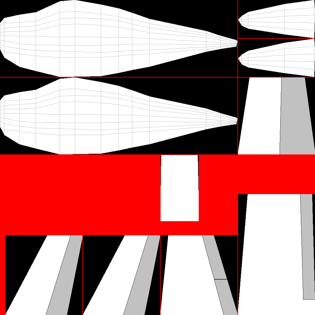
Plane Maker will automatically create one or two image files (depending on whether you used the use second texture check box) in your aircraft’s folder. It will also automatically name them properly. The first image (or the only one, as the case may be) will be called ACF file name_paint.png. The second image, where applicable, will be called ACF file name_paint2.png. Note that in order for Plane Maker and X-Plane to find the image textures, they must keep this name.
Note: You will need to re-create these starting point images each time you change the aircraft’s geometry.
Here’s what our example plane’s starting-point image looks like:
The texture map starting point for the example A36 Bonanza
Note that images used with an aircraft file should have dimensions (in pixels) that are a power of two. For instance, the image could have a resolution of 512 x 2048, 1024 x 1024, 2048 x 1024, and so on, with a maximum resolution of 2048 x 2048. The image should be saved as a PNG. The files that Plane Maker outputs will abide by these rules.
Creating the Image Textures
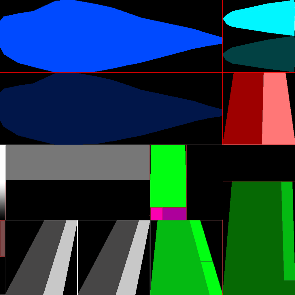
Now that the starting-point PNGs have been created, open them in your image editor of choice. While it is possible to use photos of a real aircraft to create these textures, doing so is beyond the scope of this tutorial (for information on this, see the Creating Photo-Real Paint Textures tutorial). Instead, we used our image editor to create simple textures based on solid colors.
You will probably have to go back and forth between modifying and saving your image in your graphics editor and viewing it in Plane Maker. Press the ‘t’ key in Plane Maker to quickly reload the textures displayed on the aircraft.
Here is our completed basic texture (which is also included in the aircraft package download in the introduction):
The “painted” aircraft texture
Adding a Livery
A livery is a second set of paint textures, which can be selected in X-Plane by opening the Open Aircraft dialog from under the Aircraft menu and choosing among the livery options in the bottom right box. To use an image as a livery, save it with the same name as the original paint texture (that is, as “ACF file name_paint.png”), but place it in a path that looks like this:
Aircraft folder\liveries\Name of livery\
Thus, the complete path for our example aircraft’s second livery was:
Note that you must use the same placement of the aircraft parts in each of your liveries; that is, the fuselage, wings, wheels, etc. must all be in the same place, respectively, in each image. The livery’s name in X-Plane will be listed as the folder name, thus in our example above, the second livery will be called “Labeled Parts.”
Final Notes
Once again, you can download the completed example aircraft file here: Bonanza_A36_painted.zip
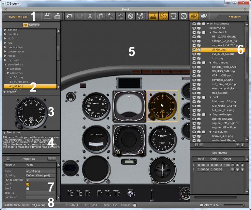
To begin, get Plane Maker running (recall that the Plane Maker application is located in the X-Plane directory) and open the Bonanza. Open the Standard menu and click Panel: 2-D. You’ll be greeted by a very plain panel background with no objects on it.
Figure 1
Creation of the panel is pretty straightforward. First, make sure the Instrument List is visible by clicking its tab if needed (labeled 1 in Figure 1 above). Find the instrument you’re looking for in the instrument list and click on it. For instance, in the image above, the general aviation altimeter (labeled 2) is selected. With an instrument selected, you can see what it will look like in the Preview tab (labeled 3 in Figure 1 above). Beneath this is the Description tab (labeled 4 in Figure 1), which details what the instrument does.
Taking up the center of the screen is the layout pane (labeled 5 in Figure 1 above). To add an instrument to the panel layout, drag it from the instrument list into this pane. Once there, click the instrument once to select it. With it selected, you can drag the instrument around to reposition it, or use the arrow keys to move it by very small amounts. If there is more than one instrument in the panel, guide lines will appear to which the instrument will “snap”, allowing you to align instruments perfectly.
When an instrument has been added to the panel layout, it will appear in the Hierarchy list (labeled 6 in Figure 1 above). You can select an instrument from the layout pane by clicking its name here. Additionally, you can set its status to visible or invisible by clicking the eye next to it, and to locked or unlocked by clicking the padlock.
To select multiple instruments, hold down either the Control or Shift keys and click as desired. To group instruments, select them and press the G key. Double-click an instrument to change its name.
When an instrument is selected in the layout and hierarchy panes, the Properties tab (labeled 7 in Figure 1) will display its settings. This includes which electrical bus the instrument is on, what Tool Tip (if any) will be displayed when it is moused over in X-Plane, and what lighting is used on the instrument.
Finally, in the very bottom of the window is the status bar (labeled 8 in Figure 1 above). Here, you can see the level of zoom for the panel layout pane, the position of the currently selected object, and its size (as a ratio compared to its original size).
Tips for the Panel Layout Pane
Use the = and – keys or your mouse wheel to zoom in and out in the panel layout pane. Right click (or hold the Control key and left click) on the panel and drag it to pan the view left and right. Hold the Alt key to view which electrical bus each instrument is on. Click and drag to form a box that selects multiple instruments. To delete an instrument, select it and hit the Backspace key.
Creating the 2-D Panel
To create our example panel, we found an image on the Web of a real A36 Bonanza’s panel and (loosely) based our instrument selection and layout on that. Creating custom instruments is beyond the scope of this tutorial, so we used the closest approximations to the real instruments that we could find in the Plane Maker instrument list. If you’re interested in creating custom instruments, see the Generic Instruments page of the Plane Maker manual.
Creating the Background
Before beginning the layout, you will want to create a basic version of the background panel image you will use. Plane Maker will supply a default panel image based on your cockpit setting in the Viewpoint window, but you may want a different image for a number of reasons.
For our example aircraft, we modified the default general aviation panel to make it 1600 pixels wide, with both “ends” of the panel visible (instead of only having the left side in the image). A width of 1600 pixels was selected so that the panel will be usable, albeit a little shortened, in the smallest X-Plane window available (which is 1024 x 768 pixels), but it will also look great in a large, widescreen window of, say, 1920 x 1080 pixels.
If you want to customize the panel background, you’ll want to create at least a basic version of it before beginning the layout so that you don’t have to rearrange or resize your instruments later.
Our example cockpit image, before customizing it, is here:
Figure 2
Panels used in Plane Maker can follow one of two naming conventions. The old convention is simply to name the file “Panel.png” (without the quotes, of course). As of version 9, Plane Maker will still find a panel named this way. The new convention, and the one you should use when creating new aircraft, is to name the image to match the panel setting in Plane Maker’s Viewpoint window.
For instance, if the cockpit setting in the Viewpoint window is set to General Aviation (as in our example Bonanza), the cockpit image will be named Panel_General.png. If it were instead an airliner, the image would be named Panel_Airliner.png.
The official names for panels are the same as in Resources/bitmaps/cockpit/-PANELS-/ and are:
Panel_General.png
Panel_Airliner.png
Panel_Fighter.png
Panel_Glider.png
Panel_Helo.png
Panel_Autogyro.png
Panel_General_IFR.png
Panel_Autogyro_Twin.png
Panel_Fighter_IFR.png
In order for Plane Maker to find your background, you must (re)name it using one of these conventions and save it in this folder:
[Your aircraft folder here]\cockpit\-PANELS-\
Thus, our example aircraft’s panel image had a full path of:
After you get your layout complete, you’ll probably want to come back to this image and customize it further–for instance, to add a column of a different color. You can find the finished version of our example Bonanza panel below.
Figure 3
Adding the Instruments
Once your Panel.jpg image has been placed in the correct folder, it should appear the next time you open the Panel window in Plane Maker. Once it’s loaded, you can begin dragging and dropping instruments from the list into your panel.
For our example panel, we chose to use the S-Tec System Fifty-Five X autopilot. This is a complete autopilot system modeled as a single instrument in X-Plane. You can find it in the “autopilot” folder in the instrument list.
You can download the .acf file of our example A36 Bonanza with the completed 2-D panel here: Bonanza_A36_with_Panel.zip
Creating a 3-D panel
Creation of a 3-D panel requires the use of a 3-D modeling program, which is beyond the scope of this tutorial. For more information, see the 3-D Panel section of the Plane Maker manual.
In this tutorial, we’ll walk through the creation of an airplane–specifically, a Beechcraft A36 Bonanza–from start to finish using Plane Maker. No prior knowledge of the Plane Maker software is required, though familiarity with the X-Plane simulator itself is assumed.
You can download the example aircraft referenced throughout this tutorial here: A36.zip
Choosing an Aircraft, Researching the Design
Plane Maker can be used to model a tremendous variety of aircraft. For the purposes of this tutorial, though, we suggest choosing a straightforward design to model. Our example craft is a Beechcraft A36 Bonanza.
In the course of creating the aircraft file, you will need a good deal of information on the actual plane, including its physical dimensions, engine and propeller specifications, weight, fuel capacity, fuel tank locations, limiting and recommended airspeeds, and so on. A web search should turn up this data for most popular planes.
Beginning the Project
To begin creating the aircraft, open the Plane Maker application found in your X-Plane installation directory.
When the window appears, open the File menu by mousing over it and click New. This will create a new, very basic aircraft file. Then, open the File menu again and click Save As. We will save our example aircraft in the “BonanzaA36” folder which we created in our X-Plane installation directory, and we’ll name it “A36.”
We’ll begin by setting a few basic parameters for our aircraft in order to the avoid the warning that pops up every time you save.
Setting the Aircraft’s Details
Open the Standard menu and click Viewpoint. The most important settings here are for the aircraft’s limits (found on the left side of the window in the Default tab). With the exception of the G-limits, these will not be factored into the flight model; they may, however, be used in the airspeed indicator. These limiting velocities are not hard to find, either in the pilot’s operating handbook or on the Web.
If you can’t find official G-limit values, 4.0 is a good guess for most general aviation aircraft. At G-loads more than 50% above these values, if the appropriate settings are enabled in X-Plane, structural damage will occur–probably in the form of a wing being torn off!
Setting the Weight and Balance
Next, open the Standard menu and click Weight & Balance. In the Center of Gravity section of this window you can set three longitudinal positions for the center of gravity, along with one vertical position. The center of the longitudinal positions is the default, while the outer two are the forward and aft limits. The center of gravity can be modified within these limits in X-Plane.
Beneath the Center of Gravity box is the Weights box. The empty weight, fuel load, and maximum weight can all easily be found from the manufacturer. Set these parameters now.
Now move to the Tanks tab of this window. There are 9 different fuel tanks available, each one holding a ratio of the maximum fuel. Note that the ratios must add up to 1. For our example Bonanza, we have two fuel tanks, one in each wing, each holding 0.5 of the total fuel. Position each tank’s center of gravity using the standard longitudinal-lateral-vertical positioning relative to the reference point.
Making A Fuselage
Preparations
If you are not familiar with the basic views and controls in Plane Maker you can review them in the section “Working with the Views” found in the Plane Maker manual.
Unless you have physical access to the aircraft you’re designing, you’ll want to find scaled images of the craft to use in the design. We found front, top, and left views of our A36 Bonanza on the Beechcraft website. These will be used as background images with which to align our design.
For use with the fuselage creation, crop your top and left images down to just the fuselage, being sure that the images are the same size and are both centered on the fuselage center.
Setting the Basics
With the images ready to go, open the Standard menu and click Fuselage.
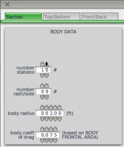
Setting the body data
In the window that appears, we’ll set the Body Data section first.
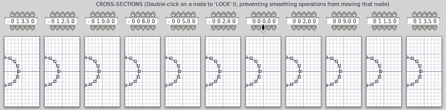
The number of stations corresponds to the number of individual sections that Plane Maker will link together to form your aircraft body, with a maximum of 20. You’ll probably want to add 2 to the number of sections you had in mind to account for the two closed ends. In our case, we will use a total of 15 sections: 13 “real” divisions, which meet at a point at each end (adding 2 extra cross sections).
The number of radii per side is the number of points used on each side of the cross section. Unless your aircraft has a very simple shape to its body, you’ll probably want to use the maximum of 9.
The body radius setting controls the width of the cross-section views below. Keep this close to the actual max body radius for accuracy when placing your points, but err on the side of setting this too big so that all your points are visible.
Finally, the body coefficient of drag controls the amount of drag generated by the fuselage. An average fuselage will have a coefficient of drag of 0.1, while a very sleek one will have a coefficient of 0.05. We didn’t have any official data on this for our Bonanza, so we chose an approximate value of 0.075.
Setting the Length
While still in the Section tab of the Fuselage window, look directly above the cross section boxes. The parameters there set the distance of each cross section relative to the reference point. The reference point can be whatever you want. Many people use the aircraft’s nose. For our example, we’ll make it the aircraft’s center.
Note that negative numbers along the longitudinal line of the aircraft (like the parameters for the cross-section placement) indicate a position forward of the reference point; positive numbers indicate a position behind the reference point.
At this point, we will set the approximate distances from the reference point for each of our cross sections (as in the image below). The most important of these will be the first and last cross sections. Since our example aircraft’s reference point is its center, the forward-most point of our aircraft will be set at -13.50 feet, and the rear-most point will be at 13.50 feet. Taking these two together, we have a 27-foot fuselage. The aircraft’s official length is 27 feet 6 inches, but since we will build the housing of our propeller separately, this should be about perfect.
Setting the approximate distances of each cross-section
With the fuselage’s length properly set, move to the Top/Bottom tab. At the bottom of the window, click Load Top Background Bitmap and select the image of the top that you worked with in the Preparations section above. Then, click the Load Left Background Bitmap button and do the same for the side image.
At this point, since the fuselage has the correct length, we need to align its two ends with the ends of the fuselage in the background images. Use the – and = keys to zoom the 3-D models out and in, and use the arrow keys to move them around.
You will likely want to return now to the Section tab to fine-tune the distances set for your cross-sections.
Setting the Radius Points
With the distances properly set, move back to the Top/Bottom tab. There, drag the radius points evenly around the fuselage visible in each of the three sections. You will likely want to use the buttons in the top right of the window to occasionally reset the cross-sections to be vertical. Note: You will likely find the Ellipse buttons (found near the bottom of the screen) helpful. Clicking this for a given cross-section will shift its points to a best-fit ellipse. To lock a point from further automatic shifting, just double-click on it (it should turn a sold black color). This may be helpful once you have them correctly established, especially the center line of each frame in the Top/Bottom tab.
Move occasionally to the Section and Front/Back tabs to check how the cross sections look from other views. You will probably find the best workflow to be something like this:
In the Top/Bottom tab, match the outer points to the fuselage edges in each of the three views.
Distribute the middle points evenly between the outer ones in each of the three views.
Move to the Section tab and modify cross sections to conform to the shape you know they should have. For instance, with our A36 Bonanza, we knew its bottom was completely flat in the middle of the plane.
Move to the Front/Back tab to fine-tune the points that are very close together.
Repeat as needed.
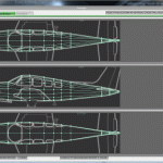
Eventually, your points should look something like this:
Finished cross sections
Finished wire model
Checking the top view of the fuselage against the background
When you’re finished, close out of the Fuselage window and load up your background bitmaps one at a time (using the button in the bottom left of the screen). Check your fuselage against each one. (Tip: use the Background menu to select whichever view you have loaded in the background.)
Designing the Wings
Now that our fuselage is finished, let’s move on to the wings. Open the Standard menu and click Wings.
In this window, you can specify four wings, a horizontal stabilizer, and two vertical stabilizers. The wings will be mirrored on each side, as will the horizontal stabilizer, whereas the horizontal stabilizer will of course only be created once. Other than this, each of the flight surfaces here behave identically.
Note that if you need more wing sections than what is available here, the Misc Wings window (which is also found in the Standard menu) allows you to specify up to 20 additional wing sections.
Creating the Main Wing
For our example Bonanza, we’ll use three wing sections, with each section meeting the one closer to the fuselage, in order to model the single wing of the actual aircraft. Each wing section can have two different airfoils set for it (one for the root and one for the tip, which are blended together in the center), as well as different control surfaces.
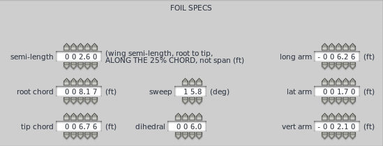
For the initial creation of each wing section, you can focus exclusively on the Foil Specs section of the window. You can enter these parameters visually if your top view scaled background image is loaded and your Plane Maker window is wide enough.
Let’s talk about these parameters a little.
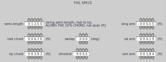
The semi-length parameter sets the length of each side of the wing as measured through the center of the wing, from the root to the tip, 25% behind the leading edge.
The root and tip chord set the width of the wing at the root (closest to the fuselage) and tip (farthest from the fuselage), measured from the leading to the trailing edge of the wing.
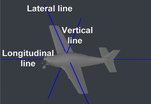
Lateral-longitudinal-vertical lines illustrated
The sweep parameter sets the angle (in degrees) that the wing is angled back.
The long, lat, and vert arm parameters set the wing’s position relative to the reference point. See the diagram to the right illustrating the longitudinal-lateral-vertical positioning system.
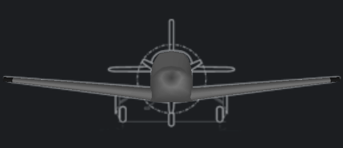
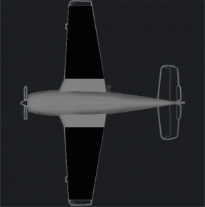
The dihedral parameter sets the angle (in degrees) that the wing is angled up. For instance, in the image below, each of the 3 wing sections used has a dihedral set between 5.5 and 6 degrees, causing the wings to angle slightly up.
Front view of a wing with a dihedral of approx. 6 degrees
Example Wings
The image below shows the foil specs used to create our innermost wing section in the G36 Bonanza. Note the 15.8 degree sweep, which creates a relatively sharp backward angle for the section.
Foil specifications for our base wing
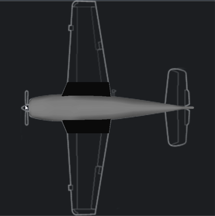
This creates a wing section that looks like this:
The base wing (in dark black)
The next image shows the foil specifications for our middle wing section, entered on the Wing 2 tab. This section is significantly longer than the base one–it has a semi-length of 12.5 feet, compared to 2.6 feet. Note also that, unlike the base wing, our mid-wing has a lateral arm specified. This moves the wing’s root out away from the body, so that it meets up with the base wing’s tip. You can have the section “snap to” the previous section by selecting Right Wing 1 from the drop down box in the top right corner of the dialog, instead of setting the wing section’s location manually using the long, lat, and vert arm boxes.
Foil specifications for our mid-wing
This creates a wing section that looks like this:
The mid-wing illustrated
Click on the Wing 3 tab to finish the tip of the wing with the specs shown in the image below.
Specs for the tip of the wing
Creating the Horizontal and Vertical Stabilizers
The horizontal stabilizer is specified just like the previous wing sections; the only difference is that it will have a much higher value for its longitudinal arm than the previous wings.
The vertical stabilizer, unlike the other wing sections here, is not mirrored on each side of the aircraft. Other than this, and its default dihedral of 90 degrees (so that it sticks straight up), you can set it just like the previous wings.
Setting the Airfoils
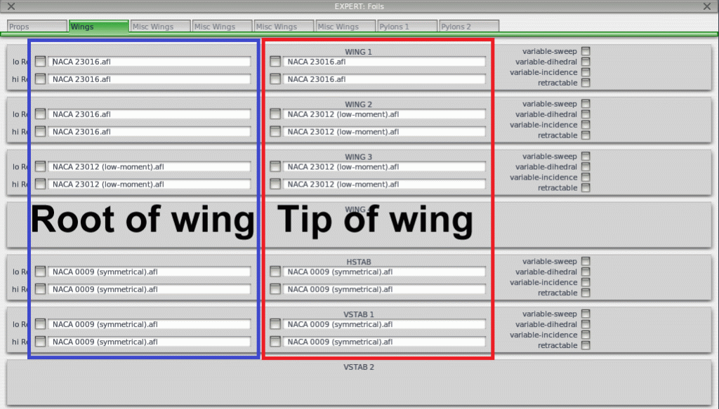
With your wings created, close out of the Wings window. Open the Expert menu and click Airfoils. In the Airfoils window, go to the Wings tab. Here, you can set two versions of both the root and the tip airfoil for each wing section. The foils on the left are for the root side of the section, and the ones on the right are for the tip side, as seen below.
The root and tip side of the the wing’s airfoil
Plane Maker will interpolate between these two foils in the middle of the wing section. The top set of foils in each wing’s box specify the low Reynolds number version of the foil; the bottom set specify the high Reynolds number version.
The following two pages may be useful in determining what airfoils to use in your wing:
To set an airfoil, click the gray box to the left of it to open your X-Plane Airfoils directory folder. Select an airfoil from among the list then click the Open Airfoil button. Remember that our wing is made up of three separate sections, so you will want to choose the same “wing root airfoil” for all four boxes for Wing 1 and Wing 2. Set the boxes of Wing 3 to the “wing tip airfoil” as it functions entirely as our wing’s tip.
Setting the Control Geometry
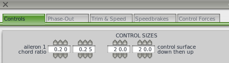
With the wings and their associated airfoils set, it’s time to set up the control surfaces. To do this, open the Standard menu and click Control Geometry. In the window that appears, a number of possible control surfaces can be specified, from ailerons to elevators to rudders to speedbrakes to flaps. Each of these work in a similar way.
In the image above, the parameter on the far left sets the control surface’s root-side width as a percentage of the root width of whatever wing section it is placed on. Thus, if this were set at 0.50 and it were used in a wing whose root was 5 feet wide, the control surface would have a root width of 2.5 feet. To the right of the root width is the tip width, also specified as a percentage of the tip width of whatever wing it is placed on. These two parameters are the same on each of the control surfaces available. Start with an amount close to the default recommended by the mouse over text.
To the right of the size parameters are the parameters controlling how far the surface can move. This will be different for each aircraft, but again start with the defaults recommended. You may need to return to this window after your first test flight to fine-tune it.
With this knowledge, specifications for ailerons, elevators, and rudders are all fairly straightforward. At the bottom of the Control Sizes box is the control surface type setting, which modifies how effective the surfaces are in X-Plane. Surfaces which are corrugated with gaps are least effective.
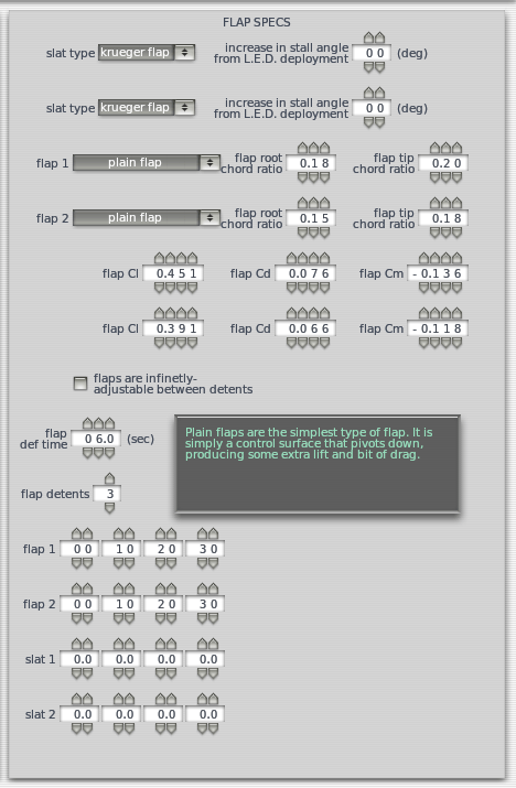
The flap settings
In the right half of this window are the flap settings, as seen in the image to the right.
Here, you can set the root and tip width ratios like the other control surfaces. You can also specify the flap type and the aerodynamic coefficients for each flap. Plane Maker will calculate the coefficients of lift (Cl), drag (Cd), and moment (Cm) based on the size of the flap, but these may be modified manually.
Beneath the coefficients, you can set the flap deflection time, the number of detents (or stop points), and the deflection at each detent. In our example, the maximum flap deflection is 30 degrees, so that is set in the last box. The first box is 0 for no deflection, and the remaining boxes in between are spaced evenly (in our case, 10 and 20 degrees).
For our example Bonanza, we specified one aileron type, one elevator, one rudder, and two flaps. We now need to add them to our wings.
Adding the Control Surfaces to the Wings
In order to see the control surfaces once we add them, open the Special menu and click Show with Still/Moving Controls. This will make the control surfaces move as we add them, so that we’ll better be able to judge where they are.
Now, open the Wings window from the Standard menu once again.
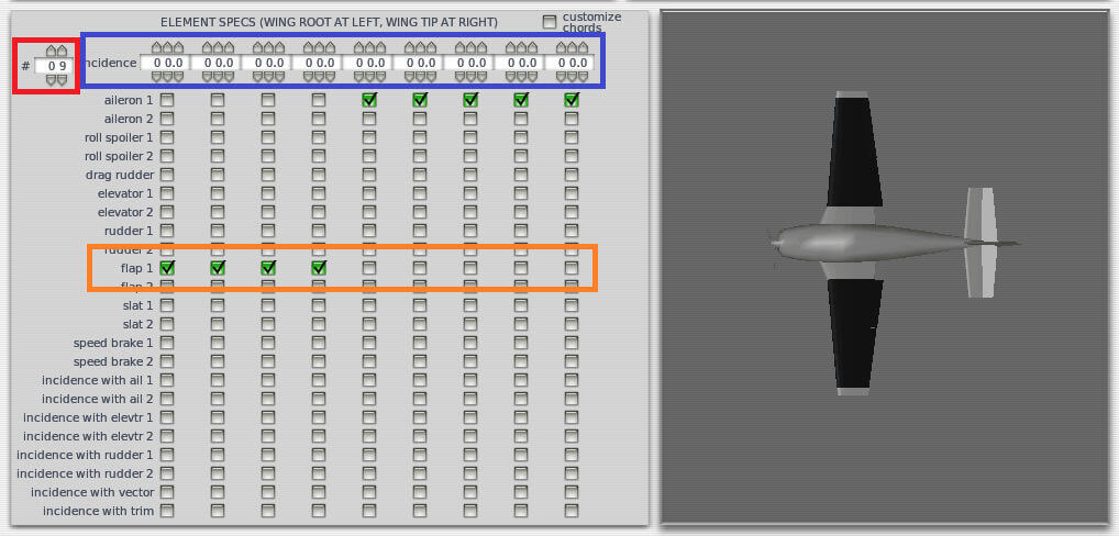
The Element Specs box with its various elements highlighted
In the Element Specs box for each wing section, you can control:
the number of pieces that this wing section will be divided into (using the parameter highlighted in red in the image above),
the incidence, or upward angling, of each “piece” (using the parameter highlighted in blue), and
the control surface (if any) present in each “piece” (using the parameter highlighted in orange).
For instance, in the image above, the middle section of our main wing is divided into 9 “pieces,” all with zero incidence. The first four pieces (the four closest to the fuselage) use the flap 1 control surface, and the last 5 pieces (the five farthest from the fuselage) use the aileron 1 control surface. Both of these control surfaces were specified in the Control Geometry window and were fine-tuned after seeing how they looked here.
Set your control surfaces as you need them for each wing section. Our Wing 1 had 8 sections with the flap 2 box checked for all but the first piece (where the wing would attach to the fuselage). Wing 3 does not move in our Bonanza so despite having multiple pieces, no control surface boxes are checked. The horizontal stabilizer is where the elevator boxes are checked and the vertical stabilizer has the rudder boxes checked.
Adding the Engine
With the wings and their associated control surfaces finished, it’s time to add an engine. To do this, open the Engine Specs window, found in the Standard menu.
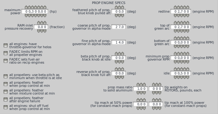
When the window opens, it will be in the Description tab. Let’s talk about the Critical Altitude box first. If your aircraft has a turbocharged reciprocating engine or a “down-rated” jet or turboprop, use the critical altitude parameter to set the maximum altitude at which the engine can put out its maximum allowed thrust. If the engine has a Full Authority Digital Engine Control (FADEC) system, check the appropriate box. Our Bonanza has neither, however, so we will leave these alone.
In the Prop Engine Specs below, you can set the engine’s maximum allowable power. For our example A36 Bonanza, this is 300 horsepower. Beneath this control are the various engine RPM settings. Note that the top of green arc and redline parameters should probably be the same. If it is a fixed-RPM engine, these should be the RPM the engine runs at. Also, the bottom of green arc should be set to zero for fixed-RPM engines.
The prop engine specs box
The rest of the prop engine settings are self-explanatory. Once these are set, move to the Location tab. Here, you can set the details of the engines and propellers, including how many there are, their type, location, RPM, etc. The parameters available here will vary depending on what type of engine you set. At the minimum, you will set the location in longitudinal-lateral-vertical arms for the center of thrust (which, for a propeller based craft, is just the center of the propeller).
Unless you have multiple transmissions or propellers, you can ignore the Transmission tab. Unless you have specific numbers on the engine’s specific fuel consumption or the propeller’s dimensions and angle of incidence, you can safely ignore the rest of the tabs here, too.
Creating an Engine Nacelle
If you created the aircraft fuselage like we did in the example Bonanza, you left off a few inches from the fuselage for the propeller and its housing. We’ll add this now around the propeller.
Open the Standard menu and click Engine Nacelles. In the window that appears, check the aircraft has a nacelle over this engine box, found near the top of the screen. From there, you can design the nacelle just like you did the fuselage. This time, though, the distances will be relative to the engine’s center of thrust, not the craft’s reference point. In our example Bonanza, we needed 6 station and 6 radii per side to model the propeller housing, with a body radius of 0.07 feet.
While designing the nacelle, you will likely find the Ellipse buttons (found near the bottom of the screen) helpful again. Clicking this for a given cross-section will shift its points to a best-fit ellipse. To lock a point from further automatic shifting, just double-click on it (it should turn a sold black color).
When you’re finished creating the nacelle, you should see the aircraft really beginning to take shape. All that’s left is to create the landing gear!
Creating a Landing Gear
Open the Standard menu and click Landing Gear. In this window, you can add up to ten different gears. For each gear, you must specify (listed in order from top to bottom in the window):
its type (e.g., skids, single wheel, double wheel in a lateral line, etc.),
its position (in longitudinal-lateral-vertical feet from the reference point),
its latitudinal and longitudinal angles when extended and retracted (where applicable),
its leg length,
its tire radius and width,
its steering ability,
the degrees that the wheels spin when retracting,
the distance that the strut compresses when retracting,
the time it takes to retract or extend the gear,
whether or not it brakes, castors or has fairing.
For our example Bonanza, we created 3 landing gears with the parameters shown below.
To finish the gear, you must go to the Gear Data tab and enter the specs for the wheels and tires, as shown below.
Adding wheel details on the Bonanza A36
The Test Flight
At this point, you aircraft is ready to be flown in X-Plane. It won’t be pretty (we haven’t added any overlay graphics or objects), and it won’t have any instruments in its panel, but it should fly just fine. Load up X-Plane, fly the plane around a bit to see how it handles, then return to Plane Maker to tweak it as needed.
Good luck!
Further Reading
For information on creating a panel for this aircraft, see the panel creation tutorial. For information on adding a paint job to the aircraft, see the paint texturing tutorial.
The latest version of the Plane Maker manual is always available online.
Comments Off on Creating a Basic Aircraft in Plane Maker
With the introduction of the new GPS/NAV/COM units we started getting bug reports like this:
New GNS430 COM Frequence not fine adjustable
COM Frequence adjustment sep between xxx.x15 to xxx.x25 is 0.010 and not 0.005 as in other range.
ATIS Frequence at airport CYUL is 120.82 and cannot be tuned in by new GNS430.
or
8.33khz tuning is wrong
The GNS430 actually does 5khz tuning not 8.33khz!
from users and authors wondering why tuning certain frequencies wouldn’t work.
Most of the confusion stems not from 8.33kHz spacing, but from failing to understand the old 25kHz spacing in the first place.
Most COM radios tune in steps of 25kHz, therefore the frequencies available starting from 118.000MHz are 118.025MHz, 118.050MHz, 118.075MHz and so on. Most radios only have five digit-displays so they can only display 5 instead of the actual 6 significant digits of the frequency.
Take for example the ATIS frequency at CYUL, which is given as 120.82. It is important to understand that the decimal value is simply cut off because most mechanical and digital radios only display two decimal digits. The frequency, however is actually 120.825 MHz and not 128.820MHz!
So to tune the frequency that on old radios read 120.82 on one of the new radios you need to tune 120.825 on the three digit display.
Some third-party aircraft allowed tuning settings like 120.81 on their radios. This is WRONG because that is not a valid COM frequency. X-Plane will snap to the nearest available multiple of 25kHz, so if you try to set a frequency of 120.81 via a plugin, using any of the COM radio datarefs, X-Plane will tune 120.800MHz which is the nearest 25kHz frequency.
With a useable COM frequency every 25kHz, the COM frequency range (the “Airband”) from 118.000MHz to 136.975MHz allows for 760 different settings (“channels”), with 100kHz on either side of the emergency frequency of 121.500MHz not assigned for safety. Now, with increasing air traffic density especially in Europe, a different, more fine-grained channel spacing was introduced to allow for even more frequencies: Instead of having a communication channel every 25kHz modern radios have a channel every 8.33kHz, tripling the number of available channels to 2280. With that kind of radio, the available frequencies become 118.000MHz, 118.0083MHz, 118.0166MHz, 118.0250MHz, 118.0333MHz and so on…
As you can see, displaying those frequencies on a radio display would be very inconvenient, because you’d need 7 digits, and reading such a frequency assignment back to an air traffic controller would be a nightmare. Therefore, 8.33kHz spaced communication channels are referred to by a channel number rather than the actual frequency. For the previously existing 25kHz-spaced channels, the channel number is identical to the frequency, so nothing changes here. For the 8.33kHz spaced channels in between that didn’t exist before, the channel is just a number, that doesn’t actually coincide with the frequency! But that does not matter at all, because charts will tell you the channel number and ATC will tell you the channel number, so if you are handed off to “132.010” you simply read back “132.010” and dial in “132.010” on your shiny new radio. In the background, it will actually tune 132.0083MHz, but you don’t care.
X-Plane deals only with channels, as do the controls of any modern radio. In X-Plane, dialling the 132.010 channel means just that – just like your charts or the ATC controller we do not care what the actual frequency is, that’s a detail left to the HF-technicians.
The same holds true for our new datarefs (introduced with X-Plane 10.30) like sim/cockpit2/radios/actuators/com1_frequency_hz_833 the dataref corresponds to what you see on your radio. It is not necessarily a frequency anymore, but a COM channel number. Only for the old 25kHz spaced channels frequency and channel number are identical.
So THAT is the full explanation why tuning one of the new COM radios looks like a “5kHz spacing, but with strange jumps here and there” and why 118.020 is not tuneable, because it is neither a valid frequency nor a valid channel number.
Still not convinced? There is a pretty good explanation by the U.K. Light aircraft association in their magazine “Light Aviation” that really explains everything, complete with a nice little table and some James Bond jokes.
Comments Off on 8.33 kHz radios for users and authors
Modern aircraft have severals devices used for navigation, usually VOR/LOC receivers for radio navigation and a GPS navigator or FMS computer for area navigation (RNAV). These devices all provide information on the course to fly, as well as some lateral offset to the planned course.
CDIs and HSIs display that information, and also feed it to the flight director or autopilot, so the pilot can track a course or radial using the desired autoflight system.
Which means of navigation is displayed on the HSI and fed into the autopilot is determined by a source selector, also called the NAV/GPS switch. Depending on the equipment in your plane, X-Plane simulates two types of source selectors found in the real world. The difference is very subtle, so here’s the full explanation:
Analog source switching
Analog source switching is found in most general aviation aircraft that have an older GPS navigator or a GPS retrofitted into the panel. In that case, you have usually two sets of wires going into the source selector, one from a VOR receiver and one from the GPS, and only one set of wires going out to the HSI. The source selector then determines whether the NAV/VOR/LOC or the GPS signal is fed to the HSI. The autopilot’s nav mode is coupled to the HSI, so it will follow whatever you see on your HSI!
In X-Plane, that type of switch can be placed on the panel, variants exist that have either NAV1/NAV2/GPS/FMS or subsets of sources selectable.
The key point to remember here is: Several signals from different devices go into the source selector, and you select one output.
Integrated NAV/GPS switching
Integrated switching is found in more modern equipment with GPS units that are approach-capable and have built-in nav receivers. An example is the very popular GNS430W by Garmin. These devices combine a NAV receiver and a GPS navigator in one piece of panel hardware. In these approach capable navigators there is usually one switch to select whether the device should output VOR or GPS navigation information. On a GNS430W that switch is labelled “CDI” and toggles a selection that can either read “VLOC”, meaning VOR or LOCalizer signal from the nav receiver, or “GPS”, meaning the GPS navigator. Because here the nav receiver is integral part of the avionic, there is no separate wiring and no separate source selector outside the device itself. The device has only one signal output, and that is fed to the HSI, CDI and/or autopilot.
The key point to remember here is: Only one signal comes from the device, and the signal’s source is determined internally.
What’s the difference in X-Plane 10.30+ ?
In X-Plane, both of these switches are controlled by the same type of panel instrument, the HSI source selector, and the same datarefs sim/cockpit2/radios/actuators/HSI_source_select_pilot for the pilot’s side and sim/cockpit2/radios/actuators/HSI_source_select_copilot for the copilot’s side.
The difference becomes obvious when you install a non-switched analogue CDI instrument in your panel:
In case of the analog HSI switch and a non-approach capable GPS or old-school FMS, the CDI is not switched and simply displays the source it has been wired to in Plane-Maker.
In case of the integrated switch, the CDI is wired to the integrated unit and it will display whatever has been selected inside this unit. You may install the CDI source indicator instrument in the panel as a visual reminder to the pilot. More modern CDIs also feature an integral green light for that.
The latter is necessary to comply with FAA-regulations: For a GPS to be approach certified, it needs to drive an external CDI or HSI. That means in panels without an HSI, the CDI has to be capable of indicating the GPS navigation, otherwise the installation cannot be certified for GPS approaches under IFR.
Comments Off on NAV/GPS Source Selectors, CDIs, HSIs and the New GPS Navigator