Beginning with X-Plane 12.3.1+, there is a new Weather (WX) radardisplay with advanced behaviors available to aircraft authors. The old, legacy composite WX display is still available as well. The new display is available in two forms. For aircraft authors, the first form is displayed via the regular EFIS map instruments found in PlaneMaker’s instrument library. For plugin authors, the second form is via a 2D RGBA return-strength texture, which provides radar return strength values in the 8-bit RED channel of the texture, from which plugin authors can read these values and render their own wx displays. Other channels in the return-strength texture are not currently used.
The radar display on X-Plane’s EFIS maps is rendered to a 24bit RGB image using a generic color stripe texture.(Resources\bitmaps\world\maps\RADAR.png). No particular effort is made to make the radar look like any specific make and model, but rather is made generically plausible to NEXRAD / FAA standards. You can customize this texture for your specific aircraft if you like by duplicating the stripe texture into a EFIS subfolder in your aircraft’s cockpit folder (not cockpit_3d) and modifying it.
About Aircraft Radar
Aircraft radar systems typically consist of a single antenna, a Processing CPU, a graphical display and various mode controls. The antenna scans a Sector Arc within the antenna’s Sweep Arc at a rate called the Scan Rate, and receives return signals which are processed and shown on a WX Display in the cockpit. The WX display screens are updated at a rate called the Refresh Rate, which most of the time, is the same as the Scan Rate, but not always. (more below)
The Sweep Arc is the maximum arc range the antenna can physically traverse, whereas the Sector Arc is the arc range actively being scanned. Most of the time, the Sector Arc = Sweep Arc for generic scanning; however, some systems have the ability to narrow the Sector Arc, in order to achieve a higher scan rate in a particular direction. The video below shows an antenna moving through its Sweep Arc.
<video or radar_sweep>
Many radar systems have antenna that can tilt up/down over a small range of angles. In simple systems, this tilt angle is manually controlled by the pilot (Manual-Tilt). In slightly more sophisticated systems, the tilt-angle can also be adjusted up or down automatically based on other factors such as pitch attitude, altitude, range settings, etc. (Auto-Tilt). In even more sophisticated systems, the antenna can automatically scan at multiple tilt angles and use those multiple scans to generate a single composite image to display to the pilots (Buffering Types). The video below shows an antenna scanning through multiple tilt angles in such a mode.
<video of multi-scan opt>
GA aircraft usually have one WX display whereas Transport Category Aircraft requiring two pilots commonly have two WX displays, one for each pilot. When two WX displays exist, one for each pilot, then each display may have its own set of controls, and when the tilt angles for each side differ, then the radar antenna is “time shared” between the displays and the Refresh Rate on each WX display then becomes <u>half</u> of the antenna Scan Rate. X-Plane can simulate Manual-Tilt, Auto-Tilt, Multi-Scanning and time shared antenna behaviors, as well as many other modes.
PlaneMaker Settings
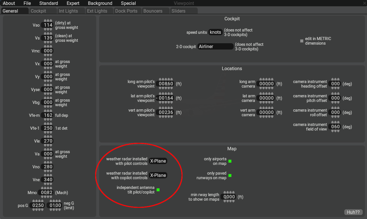
To implement the new radar, you will need PlaneMaker 12.1.TBD+ There are three configuration settings, located in the Standard Menu > Viewpoint > General Tab > Map Panel as shown below.
Each of the two pulldown menus contain the following three options:
Option
Description
None
Legacy radar image used on EFIS map instruments.
X-Plane
New radar image used on EFIS maps instruments. (using new controls/DRs/commands)
Plugin
Radar emission “return strength” values are provided via a 8-bit grayscale texture for plugins to query. (The grayscale texture may be viewed on the PM EFIS instruments.)
When both the pilot and copilot pulldowns are set to ‘X-Plane’, then a checkbox for independent antenna tilt will become available, otherwise it will be hidden. As mentioned above, when this option is enabled and the pilot/copilottilt control settings differ, then the single antenna will be time shared between the radar controls. When this option is not checked, then both WX displays will use the same tilt value. Any input on either side will be copied to the opposite side.
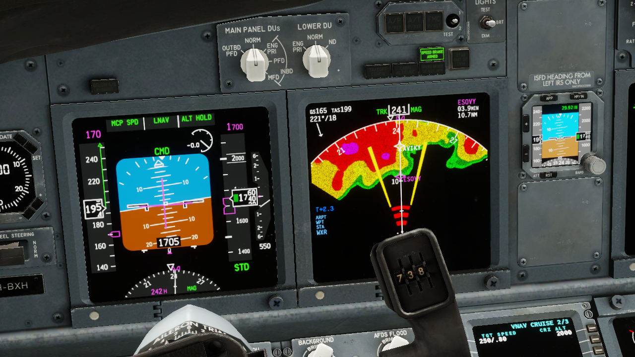
The WX radar image is rendered on PlaneMaker’s EFIS map instruments as shown below. These instruments can depict either weather or EGPWS terrain depending upon the EFIS control settings. WXR and EGPWS TERR modes (described further below) are mutually exclusive and cannot be displayed at the same time.
> NOTE: If you need EGPWS functionality, then this requires a GPS FMS instrument to be present on the 2D or 3D panel for X-Plane to load the terrain database. If your panel texture space is limited, you can use one of the screen only GPS FMS instrument options and scale it down via its Size parameter so it takes up very little texture space.
> If only WX Data is desired, with no map overlays, such as would be the case for an older, dedicated WX Display unit like a Collins IND-300 or Bendix RDS-81, then you should use the basemap_s_HM.png instrument. This instrument only displays Weather or Terrain data exclusively and is suitable for overlaying other generic or plugin generated graphics.
Plug-In Customizations
For those desiring to craft their own WX display graphics and having selected the PlugIn pulldown option in PlaneMaker, the virtual radar return strength values are written into the 8-bit RED channel of a 32-bit RGBA texture (GBA channels not used). The 8-bit value at every point represents the strength of the radar return on a scale of 0 to 255. A plugin can use this texture data to further generate and render a color grading exactly representing a particular model of radar.
The plugin can either draw to the panel texture (legacy method), or draw to an FBO of a custom avionics device using the XPLMAvionics API, which is the preferred method for plugin EFIS graphics since X-Plane 12.1. Via the XPLM Avionics draw callback, a plugin can call the XPLMGetTexture() function with the enum values xplm_Tex_Radar_Pilot or xplm_Tex_Radar_Copilot to access the texture values for subsequent graphics customization.
Operating Mode Descriptions
Before getting into the Datarefs and Commands sections below, it is helpful to discuss the various Operating Modes that Radars can employ. The table below lists all the modes available to simulate Radars of varying complexity. The modes you implement will depend upon the model of Radar you are simulating.
The Datarefs and Commands to implement the various modes are listed further below, as are additional descriptions of the various Radar types and their features.
> Note that enabling the radar on the ND (sim/cockpit2/EFIS/EFIS_weather_on) will not turn on the radar. The ND will remain empty until a discrete radar mode other than OFF is selected.
>
> When a new flight is started with engines running, the radar will default to WX+T mode, with stabilization, predictive windshear, and auto-tilt functions turned on.
Mode
Description
OFF
In this mode, the radar is not powered, the antenna does not move, and the radar image texture is cleared to all black. This is the default setting for cold & dark starts
TEST
The radar is powered in standby but not emitting radiation. A test image is displayed on the screen showing the color band of the radar.
WX
The radar is emitting radiation and sweeping the antenna left and right at the selected tilt. It detects liquid water in the air, once the droplets have reached a sufficient size. This is why it sees cumuliform clouds, which consist of comparatively large droplets, but it can’t detect stratiform clouds that are dominated by very small droplets. Only when the drops become large enough to fall out as precipitation will the radar pick up stratiform clouds. The radar cannot detect small, dry ice crystals. The tops of cumuliform clouds can reach up into very cold temperatures in the atmosphere, where the upper part of the cloud will consist of ice crystals instead of liquid water. This is called glaciation. The radar’s ability to detect these very cold particles is very limited. They can only be seen at very high gain settings, if at all. That is why the gain is increased with altitude (decreasing temperature) when left in the auto (calibrated) position. Because of the low reflectivity of dry ice crystals in very cold air, it is possible to “overscan” cumulonimbus clouds when the radar scans only the upper portions of them, where it doesn’t get a return. It is therefore necessary to tilt the radar down to scan the lower, warmer portions of cumulonimbus clouds where liquid water generates a strong return. Auto-tilt in cruise flight takes care of that by tilting the radar down. A good technique to detect cumuliform clouds from higher altitudes is to tilt the radar down until you can see the ground return at the edge of the display. Cumuliform clouds are then easily detected as they “walk out” of the ground returns. Ground returns appear when the radar beam touches the ground. Note that the beam is about 3degrees wide in either direction, so the edge of the beam touches the ground about three degrees below the actual tilt setting. The angle at which the beam strikes the ground determines the strength of the return, not the height of the elevation. Flat ground creates only weak returns, while steep mountainous terrain creates very strong returns. Ground returns will appear unless you are using ground clutter suppression, as explained below.
WX/T
The same as WX, but the areas of most severe turbulence are colored magenta. Note that turbulence detection still needs humidity. Clear-air turbulence such as orographic turbulence or jet stream shear are not detected.
TURB
Only shows magenta areas of most severe turbulence
MAP
In ground mapping mode, the radar beam is spread vertically, to scan a broader range of ground in front of the aircraft. The gain is adjusted down so less weather is picked up. Again, the strength of the ground return reflects the steepness and ruggedness of the terrain, not the elevation. MAP mode turns off any multi-scanning altitude mode, as it is normally used for ground mapping, not for examining weather at high altitudes. Selecting MAP mode turns off ground clutter suppression, if it was previously selected.
MULTI-SCAN – Auto
For Multi-Scan Buffering Radars (see Buffering Types below). This mode corresponds to flipping the multiscan switch to auto on a Rockwell/Collins multiscan radar. The tilt will be automatically controlled and scan a high and low tilt in front of the aircraft, to capture weather in a wide range of altitudes. The tilt angle displayed corresponds to the average tilt used. When OFF, the ‘nominal’ tilt-angle may be manually controlled.
ON PATH
For Elevation Buffering Radars (see Buffering Types below). This mode corresponds to setting the mode selector to AUTO or ON PATH on a Honeywell radar. The tilt is automatically adjusted up and down and the resulting radar returns are combined into a buffer. Weather in an altitude band of 4000ft above or below the airplane’s altitude (but no higher than 25.000ft and no lower than 10.000ft) is considered an ON PATH threat and shown normally. Weather outside this altitude band is considered non-threatening and shown in a subdued, striped pattern, indicating it is of less importance. As the airplane climbs or descends, weather can move into or out of the non-threatening category. Turning on the multiscan on-path mode also turns on ground clutter suppression.
ALL
For Elevation Buffering Radars (see Buffering Types below). This corresponds to switching the mode selector to ALL on a Honeywell radar. All weather is now considered threatening, not only in the above mentioned altitude band.
ELEV / ALT
For Elevation Buffering Radars (see Buffering Types below). In this mode, a single elevation can be selected with the weather radar alt dataref (or the selected altitude adjusted with the commands). Only weather in a narrow altitude band of +-500ft of the selected altitude will be shown.
PWS
<u>Predictive Wind Shear.</u> When activated, the doppler shift in returns is used to detect areas of rapidly changing wind velocity or direction. These can occur in X-Plane when a microburst is generated. When X-Plane is simulating a microburst, the PWS will generate a visual warning on the display showing the direction where to expect the microburst before the user airplane actually hits it.
If switched on, PWS works from takeoff until 100KTS and then again from liftoff to 2300ft radar altitude, and on approach once below 2300ft to 50ft radar altitude.
NOTE: Turning on PWS before takeoff turns the radar on, even if the mode selector is in the OFF position. If PWS detects windshear, it will be displayed even if the mode selector is in OFF.
GCS
<u>Ground Clutter Suppression</u><u>.</u> When activated, the ground returns of the radar are suppressed. This can make the display easier to interpret, as precipitation will be more readily seen. Note that GCS is always off in MAP mode, as this mode is explicitly for mapping the ground ahead. GCS is always off in MAP mode, and always on in multi-scan mode.
STAB
<u>Stabilization.</u> Stabilizes the radar tilt and sweep with respect to the airplane’s pitch and roll, within limits. During normal maneuvering, a stable radar image can be maintained. If this is turned off, the direction of the radar beam will be heavily affected by the airplane’s body angles, making it more difficult to interpret the image in anything but straight-and-level flight. Stabilization is always on when in a multiscan mode.
AUTO-TILT
When turned on, the manual tilt setting is ignored, and the antenna tilt is instead determined by map range and altitude. Auto-tilt will be significantly down in cruise flight, to avoid over scanning of cumulonimbus clouds. Auto-tilt is implicitly turned on when multiscan is selected, as multiscanning allows the selection of altitudes, rather than tilt angles.
AUTO-GAIN
Gain is adjusted with a rheostat (dataref) on a scale of 0..2. Lower gain helps with distinguishing benign from active clouds at lower altitudes. The higher the gain, the smaller particles (droplets, ice crystals) can be detected, which is why a higher gain is useful at higher (colder) altitudes. Note that even with the highest gain, small, dry ice crystals will not generate a return. By placing the gain knob in the middle position (dataref between 0.95 and 1.05), the gain will be automatically adjusted for altitude.
Datarefs and Commands
The full complement of radar datarefs and commands available can accommodate the simulation of a classic radar with simple controls/display, as well as a modern radar with composite buffered displays. The video below demonstrates some of the features and modes available. Subsequent sections further below describe the various dataref and commands available.
The following datarefs and commands establish operating modes for the more Basic WX radar modes. These modes are commonly found in most radar types.
Dataref
Type
Description
sim/cockpit2/EFIS/EFIS_weather_mode
int
<u>PIlot Side WX Modes</u>
0=Off/Stby,
1=Test,
2=WX,
3=WX+T,
4=MAP
5=TURB only
sim/cockpit2/EFIS/EFIS_weather_mode_copilot
int
<u>Copilot Side WX Modes:</u>
0=Off/Stby,
1=Test,
2=WX,
3=WX+T,
4=MAP
5=TURB only
BASIC WX MODE COMMANDS
------------------------
sim/instruments/EFIS_wxr_radar_off                 Weather radar OFF pilot
sim/instruments/EFIS_wxr_radar_test                Weather radar TEST pilot
sim/instruments/EFIS_wxr_radar_wx                  Weather radar WX pilot
sim/instruments/EFIS_wxr_radar_wxt                 Weather radar WX/T pilot
sim/instruments/EFIS_wxr_radar_map                 Weather radar MAP pilot
sim/instruments/EFIS_wxr_radar_turb                Weather radar TURB pilot

sim/instruments/EFIS_wxr_radar_off_copilot         Weather radar OFF copilot
sim/instruments/EFIS_wxr_radar_test_copilot        Weather radar TEST copilot
sim/instruments/EFIS_wxr_radar_wx_copilot          Weather radar WX copilot
sim/instruments/EFIS_wxr_radar_wxt_copilot         Weather radar WX/T copilot
sim/instruments/EFIS_wxr_radar_map_copilot         Weather radar MAP copilot
sim/instruments/EFIS_wxr_radar_turb_copilot        Weather radar TURB copilot
Sector Scan Controls – Datarefs
Not all radars have the same Sweep Arc range, or the ability to configure Sector Arc range. The following datarefs are used to configure the geometric parameters of the Sector Arc and Sweep Arc ranges. These datarefs are writable.
Dataref
Type
Description
sim/cockpit2/EFIS/EFIS_weather_sector_brg
float
(degrees)
The centerline angle of the sector arc, with respect to the airplane longitudinal axis. 0º = “forward”
sim/cockpit2/EFIS/EFIS_weather_sector_width
float
(degrees)
1/2 of the “total sector arc”. If this is set to 45º, the radar will scan 45º left and right of the centerline sector_brg.
sim/cockpit2/EFIS/EFIS_weather_antenna_limit
float
(degrees)
The sweep arc limit of travel, in degrees to one side of the centerline brg. Default is 45º. The antenna will <u>not</u> move past these angles.
sim/cockpit2/EFIS/EFIS_weather_sweeps_per_sec
float
The antenna scan speed. One sweep is a full cycle of the antenna, returning to the same position. If a full sweep takes 9 seconds; this DR value would be 1/9 (0.111).
> <u>NOTE</u> : The default sweep cone width is 90º. In order to widen the sweep beyond the defaults, you will need to increase both the sector_width <u>and</u> the antenna_limit DRs. Remember that the antenna will <u>not</u> move past the antenna_limit DR value.
Radar Gain Controls – Datarefs and Commands
The gain of the radar can be controlled by datarefs or commands. Note that a gain value of 1 represents the Gain Control being in the Calibrated or Auto position. In this position, the gain will be increased with increasing altitude or decreasing temperature.
Dataref
Type
Description
sim/cockpit2/EFIS/EFIS_weather_gain
float
Gain of the weather radar, From 0 to 2, where 0.95-1.05 is the 12-o’clock setting for calibrated (auto) gain.
sim/cockpit2/EFIS/EFIS_weather_gain_copilot
float
Gain of the weather radar, From 0 to 2, where 0.95-1.05 is the 12-o’clock setting for calibrated (auto) gain.
RADAR GAIN ADJUST COMMANDS
---------------------------
sim/instruments/EFIS_wxr_gain_up             Weather radar gain up pilot
sim/instruments/EFIS_wxr_gain_cal            Weather radar calibrated gain (auto) pilot
sim/instruments/EFIS_wxr_gain_down           Weather radar gain down pilot
sim/instruments/EFIS_wxr_gain_up_copilot     Weather radar gain up copilot
sim/instruments/EFIS_wxr_gain_cal_copilot    Weather radar calibrated gain (auto) copilot
sim/instruments/EFIS_wxr_gain_down_copilot   Weather radar gain down copilot
Antenna Tilt Controls – Datarefs and Commands
For some systems, the radar antenna may be tilted up or down to scan the sky slightly above and below the aircraft. In such installations, the tilt angle of the antenna can typically be set manually or automatically (Auto-Tilt). Auto-Tilt will adjust the antenna tilt angle (within its physical limits) based on the selected range, altitude of the aircraft and height of the aircraft over terrain (if within radio altimeter effective height). Auto-tilt will try to have the beam touch the ground at 80% of the selected display range. This is so that clouds can be seen “walking out” of the ground reflections. The following datarefs and commands can be used to configure the antenna tilt settings.
> Note that when the <u>first two datarefs</u> below have differing tilt values, then only if the WX radar is configured to use independent tilt controls via the PM checkbox option will the antenna actually produce differing tilt returns. In this case, as mentioned previously, the Refresh Rate of each display will be half their normal rates. If independent tilt controls are not enabled in PM, then writing to either of these dataref or using a command for either side will affect both sides equally.
Dataref
Type
Description
sim/cockpit2/EFIS/EFIS_weather_tilt
float
Degrees of antenna tilt <u>commanded</u> for pilot’s ND. -15 to +15 degrees. This is the setting on the panel.
sim/cockpit2/EFIS/EFIS_weather_tilt_copilot
float
Degrees of antenna tilt <u>commanded</u> for copilot’s ND. -15 to +15 degrees. This is the setting on the panel.
sim/cockpit2/EFIS/EFIS_weather_auto_tilt
int
0 / 1
Weather radar auto-tilt for pilot display
(manual tilt dataref ignored).
sim/cockpit2/EFIS/EFIS_weather_auto_tilt_copilot
int
0 / 1
Weather radar auto-tilt for copilot display
(manual tilt dataref ignored).
RADAR TILT COMMANDS
---------------------
sim/instruments/EFIS_wxr_tilt_up              Weather radar tilt up pilot
sim/instruments/EFIS_wxr_tilt_down            Weather radar tilt down pilot
sim/instruments/EFIS_wxr_tilt_up_copilot      Weather radar tilt up copilot
sim/instruments/EFIS_wxr_tilt_down_copilot    Weather radar tilt down copilot

sim/instruments/EFIS_wxr_auto_tilt_on             Auto Tilt On, pilot side
sim/instruments/EFIS_wxr_auto_tilt_off            Auto Tilt Off, pilot side
sim/instruments/EFIS_wxr_auto_tilt_tog            Auto Tilt Toggle, pilot side
sim/instruments/EFIS_wxr_auto_tilt_on_copilot     Auto Tilt On, copilot side
sim/instruments/EFIS_wxr_auto_tilt_off_copilot    Auto Tilt Off, copilot side
sim/instruments/EFIS_wxr_auto_tilt_tog_copilot    Auto Tilt Toggle, copilot side
For simpler, single-scan systems in manual mode, the physical tilt angle of the antenna will be the same as the commanded tilt angle set by the pilot; however, for multi-scan systems, the commanded tilt angle represents a reference tilt angle, where the antenna will scan multiple slices above and below the commanded tilt angle. As such, the physical tilt angle of the antenna at any point in time may differ from the commanded tilt angle set on the controls. You can obtain the physical tilt angle of the antenna from the following datarefs.
Dataref
Type
Description
sim/cockpit2/EFIS/EFIS_weather_tilt_antenna
float
Actual degrees of antenna tilt of the weather radar for the pilot display.
Actual degrees of antenna tilt of the weather radar for the copilot display. If differing from pilot, then antenna is being shared and display update rate is half the antenna scan rate.
Multi-Scan Buffering Radars – Datarefs and Commands
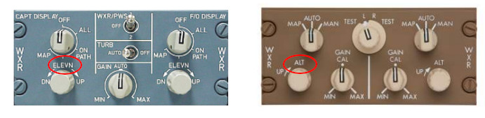
“Multi-ScanBuffering” radars are more sophisticated units with advanced CPU processors and come in two flavors: “Multi-Scan” and “Elevation”. The Elevation Type is the more advanced of the two. Both types utilize multiple scans at multiple tilt angles and save that data into a memory buffer for CPU processing. The primary distinction between the two types stem from how they post-process and display that buffered data, as well as the control inputs available. Below is an example control panel for a Multi-Scan buffering type.
The Multi-Scan Type will have Tilt Controls, which as stated previously, represents a commanded, reference tilt angle. This type of radar combines the multiple scan returns into a singular composite image that is displayed on the WX display. The composite display is essentially a layering of the multiple, angular ‘slices’.
The Elevation Type will not have any Tilt Controls, but will instead have a “Elevation” or “Altitude” control input as shown below.
The Elevation Type has more sophisticated algorithms and post-processing abilities, which allow the pilot to select a reference altitude, for which the CPU will assemble a final composite image that is relevant for the reference altitude as well as some distance above and below it. The following datarefs and commands allow you to configure the various modes available for Multi-Scan Buffering radars. Modes 0 & 1 are typical of the Multi-Scan Type and modes 2, 3 & 4 are typical of the Elevation Type. (Refer to Operating Mode Descriptions Above for each mode).
Weather radar multiscan for copilot display (ignores manual tilt dataref).
0 = Off,
1 = Combine scans (composite),
2 = Automatic altitude (on path),
3 = All Elevations,
4 = Selected Elevation (see datarefs below)
MULTISCAN MODE COMMANDS:
------------------------
sim/instruments/EFIS_wxr_multiscan_auto            Weather radar multiscan auto pilot
sim/instruments/EFIS_wxr_multiscan_on_path         Weather radar multiscan on path pilot
sim/instruments/EFIS_wxr_multiscan_all             Weather radar multiscan all elevations pilot
sim/instruments/EFIS_wxr_multiscan_elev            Weather radar multiscan one elevation pilot
sim/instruments/EFIS_wxr_multiscan_off             Weather radar multiscan off pilot
sim/instruments/EFIS_wxr_multiscan_auto_copilot    Weather radar multiscan auto copilot
sim/instruments/EFIS_wxr_multiscan_on_path_copilot Weather radar multiscan on path copilot
sim/instruments/EFIS_wxr_multiscan_all_copilot     Weather radar multiscan all elevations copilot
sim/instruments/EFIS_wxr_multiscan_elev_copilot    Weather radar multiscan one elevation copilot
sim/instruments/EFIS_wxr_multiscan_off_copilot     Weather radar multiscan off copilot
When in Mode 4 (selected elevation), you can use the following datarefs or commands to configure the selected reference elevation / altitude. Note that using these commands or writing to these datarefs will reset the tilt to 0º and display a flat horizontal slice at the selected altitude.
Dataref
Type
Description
sim/cockpit2/EFIS/EFIS_weather_alt
float
In Feet. Weather radar buffer selected altitude pilot’s ND – used in computerized weather radar systems instead of tilt. Defaults to -1000 when angular tilt is used.
sim/cockpit2/EFIS/EFIS_weather_alt_copilot
float
In Feet. Weather radar buffer selected altitude copilot’s ND – used in computerized weather radar systems instead of tilt. Defaults to -1000 when angular tilt is used.
RADAR ALT SELECTION COMMANDS
-------------------------------
sim/instruments/EFIS_wxr_alt_up                Weather radar alt up pilot
sim/instruments/EFIS_wxr_alt_down              Weather radar alt down pilot
sim/instruments/EFIS_wxr_alt_up_copilot        Weather radar alt up copilot
sim/instruments/EFIS_wxr_alt_down_copilot      Weather radar alt down copilot
Auxiliary Modes – Datarefs and Commands
Radar systems can have auxiliary sub-modes for various purposes to improve the display or detect windshear. The following datarefs and commands can be used to manage the radar sub-modes.
Dataref
Type
Description
sim/cockpit2/EFIS/EFIS_weather_stab
int (0 / 1)
Pitch/roll STABilization.
sim/cockpit2/EFIS/EFIS_weather_stab_copilot
int (0 / 1)
Pitch/roll STABilization, copilot side.
sim/cockpit2/EFIS/EFIS_weather_gcs
int (0 / 1)
Weather radar Ground Clutter Suppression.
sim/cockpit2/EFIS/EFIS_weather_gcs_copilot
int (0 / 1)
Ground Clutter suppression, copilot.
sim/cockpit2/EFIS/EFIS_weather_pws
int (0 / 1)
Predictive WindShear system.
sim/cockpit2/EFIS/EFIS_weather_pws_copilot
int (0 / 1)
Predictive WindShear system, copilot.
AUXILIARY MODE COMMANDS
-------------------------
sim/instruments/EFIS_wxr_stab_on              Weather radar stabilization on pilot
sim/instruments/EFIS_wxr_stab_off             Weather radar stabilization off pilot
sim/instruments/EFIS_wxr_stab_tog             Weather radar stabilization toggle pilot
sim/instruments/EFIS_wxr_stab_on_copilot      Weather radar stabilization on copilot
sim/instruments/EFIS_wxr_stab_off_copilot     Weather radar stabilization off copilot
sim/instruments/EFIS_wxr_stab_tog_copilot     Weather radar stabilization toggle copilot
sim/instruments/EFIS_wxr_gcs_on               Weather radar ground clutter supression on pilot
sim/instruments/EFIS_wxr_gcs_off              Weather radar ground clutter supression off pilot
sim/instruments/EFIS_wxr_gcs_tog              Weather radar ground clutter supression toggle pilot
sim/instruments/EFIS_wxr_gcs_on_copilot       Weather radar ground clutter supression on copilot
sim/instruments/EFIS_wxr_gcs_off_copilot      Weather radar ground clutter supression off copilot
sim/instruments/EFIS_wxr_gcs_tog_copilot      Weather radar ground clutter supression toggle copilot
sim/instruments/EFIS_wxr_pws_on               Weather radar predictive windshear on pilot
sim/instruments/EFIS_wxr_pws_off              Weather radar predictive windshear off pilot
sim/instruments/EFIS_wxr_pws_tog              Weather radar predictive windshear toggle pilot
sim/instruments/EFIS_wxr_pws_on_copilot       Weather radar predictive windshear on copilot
sim/instruments/EFIS_wxr_pws_off_copilot      Weather radar predictive windshear off copilot
sim/instruments/EFIS_wxr_pws_tog_copilot      Weather radar predictive windshear toggle copilot
Unlike on cars with hydraulic brakes and a cable-operated E-brake, most airplanes only have one braking system, that is most commonly hydraulically operated. Most airplanes have individual brakes for the left and right main gear that are actuated with toe brake pedals. Some airplanes, like the PA-28, have a common brake handle that allows to actuate both brakes evenly at once. The common brake handle can be arrested in position to serve as parking brake. The mechanism is essentially the same between PA-28 and C-172, pulling and locking the brake handle applies brake pressure to both wheel brakes, and the handle mechanically locked in place keeps this pressure up. Other airplanes, like the DA-40 or most airliners, employ a different mechanism: A hydraulic valve that traps brake pressure in the gear system, isolating the brake pedals from the gear. In that case, the pilot applies brake pressure with the pedals, and then closes the valve which traps the pressure. The pedals can then be released, but the brake calipers will apply pressure for a long time, if the system is tight and leak-free.
Anti-skid and feathering the brake pedal
Many airplanes have an anti-skid system that prevents the wheels from locking up under excessive brake force. On many airliners this system is so good, that no matter the runway conditions simply pushing the brakes as hard as you can and leaving the work to the anti-skid system will result in the shortest stopping distance. X-Plane works the same and allows you to fully push the toe brake pedals (or pulling the wheel brake handle) even on an icy runway and will feather the brakes for you.
However, if selected in Plane Maker, an airplane can have no anti-skid system installed (or the system could have failed). In this case, you need to carefully apply the wheel brakes to prevent wheel locking. This is easy with an analogue control axis for the brake, like hardware rudder pedals provide. Users with no hardware pedals can use the “hold brake” commands – they build up brake pressure over time as they are being held down and release it when the key or button for the command is released. With a little practice, quick pushing and releasing of the button can be used to meter brake effort.
Airplane Options in Plane Maker
“Hydraulic parking brake valve” is the new option to have a valve to trap the pressure downstream from the pedals. Aircraft pre-dating Plane Maker 12.1 will default to not having this valve and using a physically locking handle.
“Toe brakes can release park brake” is an option that exist on some planes with a parking brake valve that forcefully opens the valve when the toe brakes are pushed. Not all airplanes work that way. Aircraft pre-dating Plane Maker 12.1 will default to having this on, as it matches behavior of X-Plane 11
“Anti-skid system” equips the airplane with an essentially “always-on” anti-skid system that allows the user to always use full brake pressure and not be afraid of skidding even under slippery conditions. Aircraft pre-dating Plane Maker 12.1 will default to having this on, as it matches the behavior of X-Plane 11.
Wheel chocks
Wheel chocks are another way to secure an airplane in place, as parking brakes tend to lose pressure over time. Placing a chock under the wheel prevents it from moving. It is physically different from a parking brake: in X-Plane, this is simulated by keeping the tire contact patch locked in place, rather than resisting rotation by applying a brake torque. Since the chocks can be placed individually per-wheel, the airplane can be held in place by locking some wheels, even when others need to be able to move freely, such as when the gear geometry changes due to loading or unloading the aircraft while parked.
Commands and DataRefs
sim/flight_controls/brakes_toggle_regular Applies a moderate braking pressure, depending on the aircrafts weight.
sim/flight_controls/brakes_toggle_max Applies the maximum braking pressure, regardless of environment. This can lock the wheels on a plane with no anti-skid. When used on a plane with no parking brake valve, equivalent to pulling the brake handle out to maximum and locking it. When used on a plane with parking brake valve, equivalent to holding both brake pedals fully down with continuous foot pressure. Note that over the course of an hour, pressure can seep, and brakes will need to be re-applied. Use the real parking brake valve if you want it!
sim/flight_controls/brakes_regular If held continuously: applies a moderate braking pressure, depending on the aircrafts weight. Since brake pressure goes away on command release, this can be used to feather the brakes up to a medium pressure.
sim/flight_controls/brakes_max If held continuously: applies the maximum braking pressure, which can cause skidding in a plane with no anti-skid system. Since brake pressure goes away on command release, this can be used to feather the brakes up to a maximum pressure.
sim/flight_controls/park_brake_set (new): Applies brake pressure and then locks it in place by closing the parking brake valve, if the plane is so equipped. If not, functionally equivalent to brakes_toggle_max
sim/flight_controls/park_brake_release (new): Opens the parking brake valve and lets brake pressure escape. On planes with no valve, equivalent to releasing the handle.
sim/flight_controls/park_brake_toggle (new): toggles between pressurized, valve closed, and unpressurized, valve open on planes with a valve, otherwise functionally equivalent to brakes_toggle_max
sim/flight_controls/park_brake_valve_close (new): Closes the parking brake valve and maintains whatever pressure existed. Note that when closed without actually applying brake pressure before, it will completely disable the brakes. Does nothing on planes without such a valve.
sim/flight_controls/park_brake_valve_open (new): Opens the parking brake valve allowing trapped pressure to escape, resulting in brakes being released. Does nothing on planes without such a valve.
sim/flight_controls/park_brake_valve_toggle (new): Toggles the valve between open and closed on planes that have it.
sim/flight_controls/install_chocks (new): Chocks all wheels of the airplane.
sim/flight_controls/remove_chocks (new): Removes wheel chocks from all wheels.
sim/flight_controls/toggle_chocks (new): Toggles all wheel chocks between installed and removed.
sim/aircraft/gear/acf_has_abs              int         y   boolean   Wheel brakes fitted with an anti-lock system that will automatically prevent skidding
sim/aircraft/gear/acf_park_brake_trap      int         y   boolean   Hydraulic wheelbrake uses a valve to trap pressure for the parking brake
sim/aircraft/gear/acf_park_brake_toe       int         y   boolean   Parking brake (or parking brake valve) can be released by pushing the toe brakes
sim/cockpit2/controls/parking_brake_ratio (this is REPLACED),
     -Use wheel_brake_ratio dataref below instead.
sim/cockpit2/controls/wheel_brake_ratio    float      y   ratio      The overall brake requested by the master brake cylinder... 0.0 is none, 1.0 is complete.
sim/cockpit2/controls/park_brake_valve     int        y   boolean    Some hydraulic brake systems have a valve that can be closed to trap brake pressure for the parking brake. 0 = Normal (valve open), 1 = Closed (pressure trapped for park brake)
sim/flightmodel2/gear/tire_abs_gain        float[10]  n   ratio      How much ABS is limiting the brake force applied to the caliper (1 means full braking, 0 means brakes fully released)
sim/flightmodel2/gear/is_chocked           int[10]    y   boolean    Is the tire chocked - it's blocked in place and can't be moved regardless of brake setting
X-Plane 12 can simulate both ice accumulation and window de-ice effects as well as rain drop/wiper visual effects on aircraft window surfaces. This article explains how to implement icing visual effects only. Rain effects are discussed in its own dedicated article, “Windshield Rain Effects”. This article assumes you are familiar with:
💡 NOTE: X-Plane 12.1+ introduces significant changes to the windshield ice and heat simulation from previous versions, which had many problems. Any RainGlass OBJs previously configured with THERMAL sources, and exporting from XP2B V4.3+ using an export target version prior to 12.1 will NOT have window heat functionality. The exporting of the legacy THERMAL_source directive have been removed for all XP version options prior to 12.1.
If you have exported out RainGlass OBJs with XP2B 4.3+ to support XP targets < 12.1, yet still desire to use the legacy THERMAL_source directive, then you will need to manually edit the OBJ and enter the directive and its parameters by hand. This directive and parameters are described further below for reference.
Enabling Ice Effects
Ice effects are automatically included on any window OBJs configured for Rain Effects. See the Rain Effects document for more info if you haven’t set up your RainGlass OBJs yet. When the conditions warrant, and in the absence of any window heat, the window will begin icing over uniformly at a rate dependent upon the conditions. X-Plane’s icing algorithm considers temperature, moisture, airflow and heating when calculating ice accumulation on RainGlass OBJs.
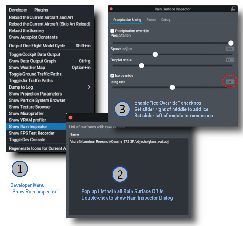
Icing Inspector Tool
The same tool that is used to debug / inspect Rain Effects is also used to debug / inspect icing effects, so you don’t have to configure X-Plane’s weather to test your work. The image below shows the sequence for use.
💡 NOTE: For the “Icing Rate” slider. The middle position is 0 (red circle below). The right side of the slider adds ice and the left side of the slider will remove ice. If you are wanting to test your thermal texture deicing effects quickly, you will probably want to move the slider to the right to add ice, and then return it to the middle zero position and then activate the window de-ice system to observe the effects of your thermal gradient texture.
Thermal Sources Gradient Texture
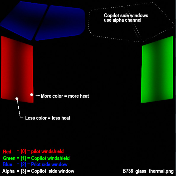
In reality, windshields are typically deiced using either resistance (electrical) heating elements, or by using hot air blowers. Both of these are examples of thermal sources. Thermal sources typically apply heat to specific areas of the windshield glass and the heat radiates out from that area across the windshield. This causes the ice to melt in a progressive pattern, melting nearest the heat source first and progressing from there. X-Plane models the progression of this heat flow via a 8-bit RGBA “thermal texture”, UV mapped to your RainGlass OBJ and using color gradients across the UV islands of the windows to model the movement of the heat.
X-Plane uses the four channels of the thermal texture to simulate up to four independent thermal sources. Most aircraft typically have only one or two thermal sources.
The image below shows an example texture where a fully saturated color pixel, i.e. 100% Red, Geen, Blue or Alpha(white) represents maximum heat flux and a fully black pixel represents zero heat flux. Note in the example below that there are no fully black pixels on the window glass because if there were, the window heat would not melt ice in these locations.
The gradient texture is quite straightforward, typically painted by hand using gradient tools in graphic apps like Photoshop or GIMP. Remember that a fully black alpha channel (when thermal source [3] is not used), will make your image transparent.
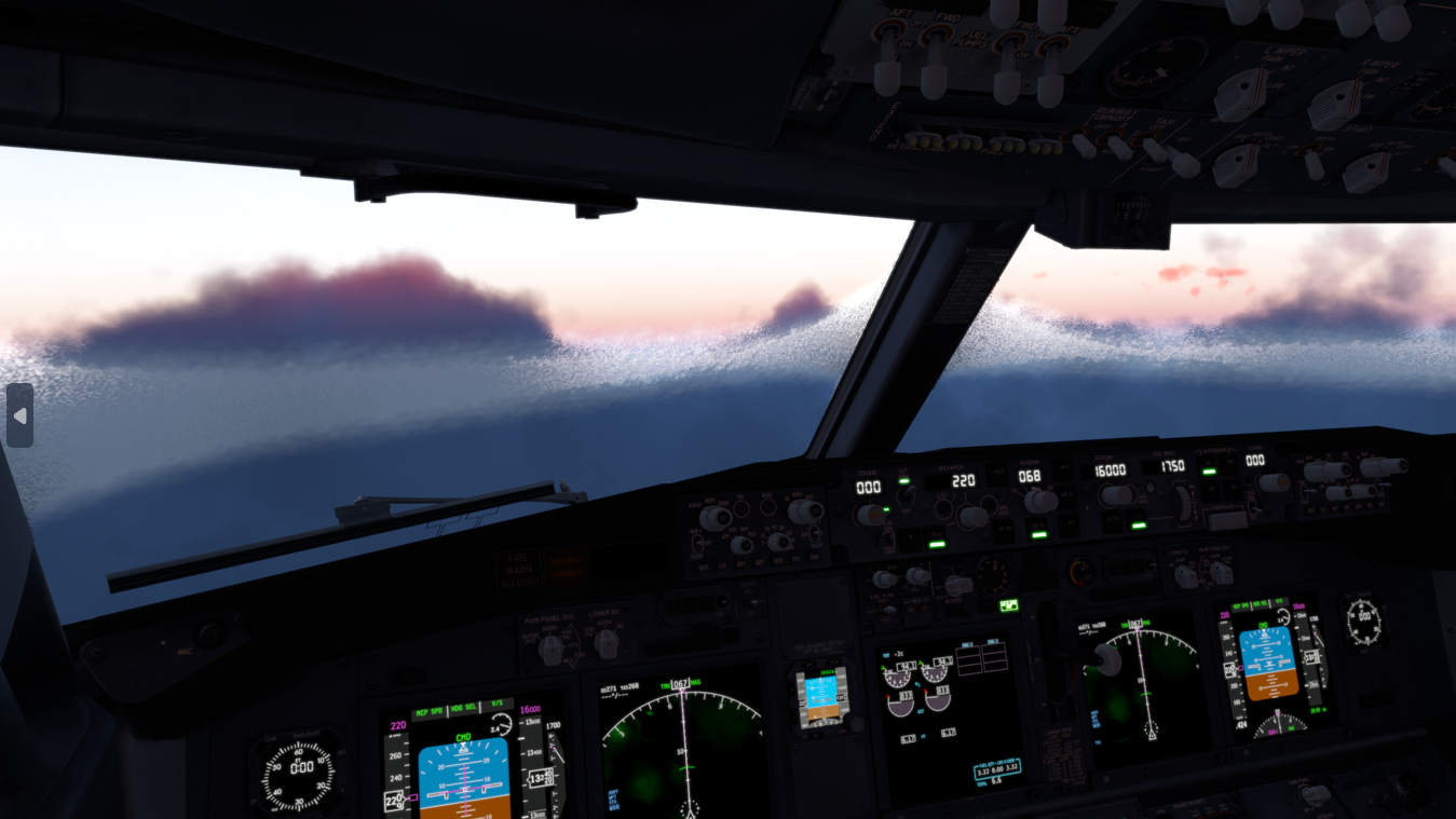
The image above illustrates how the thermal sources for the main windshields (Red and Green), are at the top and bottom of the windshields, and ice melts there first and then the heat moves towards the center of the window. In X-Plane the effect looks like so. For a hot-air blower fan configuration, you may have a radial type of gradient pattern, etc.
💡 TIP: Use a lower resolution THERMAL_texture to achieve better and more realistic looking heat propogation behaviours.
XPlane2Blender Settings
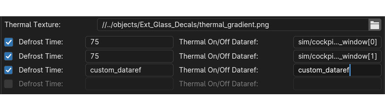
The XP2B settings for the thermal sources for window heat are found on Blender’s Scene tab in the collection settings (see image below). To configure your window heat, you enter the path to your thermal sources texture, presumably in the objects folder somewhere, and you enable however many thermal sources you need, up to 4 total.
For each thermal source you enable, you enter the Defrost time, in seconds. This field can be a fixed number or a dataref. This time represents how long, in seconds, a thermal source takes to fully deice a fully iced over window, assuming no ongoing ice accumulation. A shorter time represents more heating power. If you use a dataref, then you can alter this value at run time to simulate adjustable heating levels.
Next you enter the Thermal ON/OFF dataref. These datarefs, when 0, disable the window heat and when non-zero (usually 1), enable the window-heat. X-Plane have default datarefs for turning the window-heat ON/OFF for each source, which are listed further below.
The thermal settings in Blender will be exported to the OBJ GLOBAL settings in the form of two directives in the OBJ header section: one entry for the thermal texture file/path and one entry for each thermal source configured in Blender.
THERMAL_texture    path/to/texture/thermal_texture.pn;
THERMAL_source2   <index>    <rate_seconds or rate dataref>   <on/off dataref>
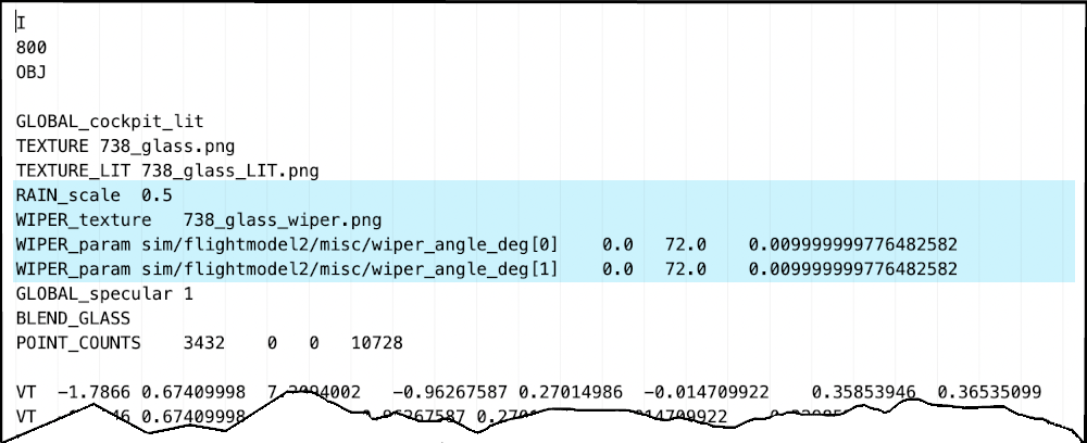
The exported windshield heat thermal parameters for the default B738, which uses four sources are shown below. Note that the ON/OFF datarefs are X-Plane’s status datarefs and not the window heat actuator/switch datarefs. The status datarefs take into account any system failures. You don’t want your window heat effects to be ON if the system is failed.
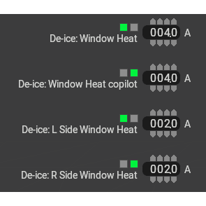
Power Consumption
You can configure the power consumption of each thermal source via PlaneMakers’s Standard Menu > Systems > Bus Loads Tab (the first one). When the status datarefs are 1, then X-Plane will add a current load to your electrical buses. These are fixed electrical loads only.
If you need to simulate a variable power window heat system and want to vary the power consumption of the thermal sources, then you will have to do so via plugin, adjusting your defrost time via dataref, calculating your power consumption and adding the load to a bus via sim/cockpit2/electrical/plugin_bus_load_amps[n]
Icing Commands and Datarefs
The following datarefs and commands are used with the Window heat / icing system.
        //  Actuator Datarefs (switch, button, whatever)
        sim/cockpit/switches/anti_ice_window_heat       // switch, 1st window
        sim/cockpit2/ice/ice_window_heat_on_window[N]   // switch, where N = 0-3

        // Actuator Commands
        sim/ice/window_heat_on                          // 1st window
        sim/ice/window_heat_off
        sim/ice/window_heat_toggle

        sim/ice/window2_heat_on                         // 2nd window
        sim/ice/window2_heat_off
        sim/ice/window2_heat_toggle

        sim/ice/window3_heat_on                         // 3rd window
        sim/ice/window3_heat_off
        sim/ice/window3_heat_toggle

        sim/ice/window4_heat_on                         // 4th window
        sim/ice/window4_heat_off
        sim/ice/window5_heat_toggle

        //  Status Datarefs.  Takes into account failures. e.g. can drive annuns
        sim/cockpit2/ice/ice_window_heat_on             // status, 1 window only
        sim/cockpit2/ice/ice_window_heat_running[N]     // status

        //  Failure State Datarefs
        sim/operation/failures/rel_ice_window_heat
        sim/operation/failures/rel_ice_window_heat_cop
        sim/operation/failures/rel_ice_window_heat_l_side
        sim/operation/failures/rel_ice_window_heat_r_side
Legacy Icing
It’s highly recommended to use the THERMAL_source2 directive with X-Plane 12.1.0 for any new aircraft development. The legacy THERMAL_source command still works in X-Plane 12.1.0, but the visual icing effects have inconsistencies with the X-Plane systems model with regards to how much ice X-Plane tracks on the windshield versus how much is visually rendered.
The syntax for the legacy THERMAL_source command is:
THERMAL_source <heat in ºC dataref> <on/off dataref>
…where the <heat in ºC dataref> is clamped between 5º and 20º C and then gets interpolated into a rate between 5 and 20 seconds.
💡 NOTE: Detail Textures were previously referred to as “DECALS”. The term DECAL is a legacy term. The OBJ directives: DECAL_PARAMS and NORMAL_DECAL_PARAMS are part of the OBJ specification and will not change; however, the term “Detail Textures (DTs)” are the official name for these specific texture types.
As of XP2B v4.3.3, the label “Decal” is used in the UI panels. Future versions of XP2B will adopt the label “Detail Texture” in lieu of “Decal”. Until such changes are integrated into XP2B, consider the terms interchangable in the meantime.
Introduction
Detail Textures, (DTs) are tileable, repeating textures that can be overlaid / mixed with either your OBJ albedo or normal textures. They were designed to add higher density textural detail without having to resort to large texel densities to capture those small details. Detail Textures were designed for use with ground textures but adapted for aircraft use; therefore, many of the XP2B DT configuration settings are not applicable for use in aircraft.
The image below shows DTs used to portray textured plastic and vinyl grain, where the albedo and DT texel densities are quite low, yet the DT overlay resolution is effectively higher because it is scaled down and tiled. By using less UV space on your albedo textures for these broadly colored areas, this frees up UV space to increase your texel density in other areas of your OBJ, or allow you to reduce the size of your albedo textures for more efficient VRAM usage.
Detail Texture Concepts
Refer to the image below:
An OBJ may have up to two DT Slots. Each slot may contain a ‘DT Albedo’ and a ‘DT Normal’ texture. Either DT in each slot may be used, one does not require the other. The example above only utilizes Normal DTs. The Albedo DT can have an alpha channel; however, the Normal DT ignores both the blue and alpha channels. Only the Red and Green channels of the Normal DT are utilized for normal/bump effects.
Each DT slot has its own scaling parameter. In the example below left, DT Slot 1 has a scale of 0.25 and DT Slot 2 has a scale of 0.5.
When using Albedo DTs, the color mixing with the Base Albedos is established by a graphics shader. There is no configurable ‘mixing mode’ such as “multiply / add / overlay”, and for Albedo DTs containing high saturation hues, the results can be unpredictable. Albedo DTs for aircraft use are best suited for adding lower saturation hues.
DTs are tiled orthogonally, there is no provision to rotate the tiled pattern.
An optional Red / Green channel Modulator Texture (MT) may be utilized as a mask, to control where DT1 and DT2 are applied to the Base Albedo texture.
A Base Albedo texture is required to use Albedo DTs and a Base Normal Texture is required to use Normal DTs.
The XPlane2Blender settings for Detail Textures (DTs) are found on the Scene Properties Tab as shown below. Additional fields will appear once you enter the DT filenames. The image below shows the XP2B UI widgets for Albedo DT and one Normal DT. The good news is that for aircraft use, we do not need too many of these options. The highlighted areas in green are the only fields you need to be concerned with for aircraft use. The others fields are used for scenery development and ground texture DTs. Each field is as follows:
SCALE: The scale isn’t exactly a scale factor in the typical sense, but rather the “number of tiles” along the edge of the albedo, ergo it is the inverse of the scaling factor. In the example above left, the scale would be 4. This field should be a value ≥ 2. One tile makes no sense as you could just mix the textures together in Photoshop.
RGB Decal Modulator Strength: This is most easily described as a type of opacity or ‘strengh of effect’ value. A value of 1 mixes the DTs with the Base Albedo with full strength. Lower values reduce the effect of the DTs. (Example further below). A value of zero effectively negates the DT effect.
Modulator Strength: Same as above, but for the DT Normal Texture.
Modulator Texture: A Red/Green channel texture to use as a mask for DTs 1 and 2. The red channel of the Modulator Texture will control where DT1 is applied and the green channel controls where DT2 is applied. The Red and Green channels may be mixed to apply both DT1 and DT2 to the same area of the texture. If no Modulator Texture is specified, then the DTs will be applied uniformly over the entire Base Albedo.
Examples
The best way to illustrate the use of Detail Textures are with examples. We are going to start simple and get progressively more complex. We will be using the following Objects and Textures below in our example. We have two Albedo DTs and 3 Normal DTs to work with, in addition to our Base Albedo and Normal textures.
This is what it looks like in X-Plane without any Detail Textures applied:
Normal Detail Textures
We first begin with normal textures, because they are the most likely application with aircraft. We apply a Leather grain normal texture (256px) by specifying leather_NML.png as Detail Texture 1, setting the Modulator Strength to 1 and arbitrarily set the scale/tiles to 50. The results look like so.
In the above image, note that the effect is applied over the entire OBJ, including the knob because no modulator texture was specified to mask areas of the texture. We will now specify a modulator texture to limit the leather grain effect to just the gauge surround using the RED channel, since this is a Slot 1 detail texture.
In the image below, the settings are the same as above, except for the addition of the Modulator Texture, “decal_mask.png”. Some of the gauge surround now have DT Effects (yellow mask) and some areas have no DT effects (black areas of mask = no effects). Note that YELLOW is equal parts RED and GREEN so any UV islands mapped to yellow will receive both DT1 and DT2 effects; however, because no DT2 has been specified yet, only DT1 shows up on the gauge surround. Lets add a second Normal DT texture to add some noise on top of the leather grain.
In the image below, we have added a second Normal Map Decal 2 with the 3 settings in XP2B circled in red. Because this is DT2, it is masked with the GREEN color channel. Since the knob UV is masked with GREEN, it receives the noise DT, but not the leather DT. The leather DT is indeed on the gauge surround, but it is overpowered by the noise DT effect. Lets reduce the Modulator Strength of the Noise DT a bit and scale up the leather DT slightly so we can see both effects on the gauge surround due to the YELLOW mask.
In the image below, you can see how the gauge surround now has both leather and noise normal effects. Also note how the modulator Strength reduces the effect of the Noise DT. Once you have specified your Normal DTs, simply adjust the Scale and Modulator Strength values to tweak the effect. Lets wrap up this section on Normal DTs with one last example. We’ll swap out the noise DT for the knurl_NML.png DT and set the Modulator Strength back to 1. The result is shown in the 2nd image below.
Albedo Detail Textures
Albedo textures are configured in the exact same way as the Normal DTs. Though there are more UI Widgets available for the Albedo DTs (for scenery textures), for aircraft you still only work with the same two input types as for Normal DTs, i.e. the Scale value and the RGB Decal Modulator Strength value.
As mentioned above, the color mixing of the Albedo DT with the Base Albedo is non-intuitive. The example below left shows a low-contrast noise_ALB.png added to the flat plate to add some grayscale noise color. The middle image shows the same flat plate, but with the noise Normal DT added in also. The right image shows a second, high contrast Albedo DT added, dots_ALB.png and illustrates how the color mixing of the Albedo DT with the Base Albedo yields a not so intuitive result that differs based on the pixels of the Base Albedo. (See original texture, dots_ALB.png texture above). Albedo DTs are best for applying more saturated, low-contrast colors, such as grime and dirt or to disrupt a bit of color uniformity.
OBJ Output
The image below shows the typical entries in the OBJ header for Detail Textures as XP2B exports the data. The order of the entries in the OBJ determines whether or not a Detail Texture is in Slot 1 or 2, and therefore, which will be affected by the RED and GREEN channels if a modulator texture is used. The XPlane2Blender UI references DTs 1 and 2, but this is semantic. If you specify DTs in XP2B in the DT2 slots, but leave the DT1 slots empty, then only one slot will be used in the OBJ and as such, any modulator ‘masking’ would be controlled by the RED channel. Best practice in XP2B is to simply use the DTs in order, i.e. DT1, then DT2 if required.
Summary Review
Take advantage of why Detail Textures exist, i.e. save VRAM by using smaller textures where you are able. If you use a Detail Texture with a scale factor (tiling) of 1, there is no benefit.
Keep texel densities the same for UV islands that use the same Detail Textures so the effect is consistent across all meshes using it.
Use the Detail Texture Slots in the order they appear in XP2B, i.e. DT1, then DT2
To recap, the Modulator Texture is for masking, the RED channel is the mask for Detail Texture 1 and the GREEN channel is the mask for Detail Texture 2.
X-Plane 12 can simulate both rain drop/wiper visual effects as well as icing and window heat effects on aircraft window surfaces. This article explains how to implement and calibrate rain effects only. Icing effects are discussed in its own dedicated article, “Windshield Ice Effects”. This article assumes you are familiar with:
The 3D OBJs to receive rain effects should only contain polygons for surfaces with rain effects. Do not include opaque or non-rain-effects polygons as part of your rain-glass objects.
You should expect to use two separate OBJs to represent your rain glass: one OBJ with outward facing normals and another OBJ with inward (cockpit/cabin) facing normals. Best practice is to name these two OBJs as follows for clarity reasons:
Each individual window should to be a continuous, manifold mesh in 3D with no UV seams, so that when UV unwrapped, the resulting UV island mesh is also continuous. Do not split up a singular window into multiple UV islands.
No UV island of any one window should overlap another on the texture. UV islands should have consistent texel densities between them and minimal warping for consistent rain drop sizes.
Any transparent meshes inside the aircraft, (typically translucent sun-visors) where you need to see the rain effects through these meshes, should be part of the inside_reflector object; however, the draw-order of the meshes within that OBJ may need to be configured (more below).
While you CAN use multiple OBJs set to Outside Rain Glass, this is not recommended. You should endeavor to use one OBJ for all external glass with rain effects and a second OBJ for all the inside (reflector) facing glass.
Enabling Rain Effects on OBJs
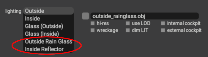
Rain effects can be enabled on your window OBJs by setting their lighting mode in PlaneMaker to either Outside Rain Glass or Inside Reflector. Use Outside Rain Glass for your OBJ with outward facing normals and use Inside Reflector for any windows (or visors) with inside/cockpit/cabin facing normals.
These two OBJ lighting settings are complementary and intended to be used together. If not utilized together, then inconsistent rain effects in various X-Plane views may result. X-Plane will simulate raindrops on these OBJ meshes, including the effects of gravity and aerodynamic forces.
UV Considerations for Rain Glass
To avoid differing raindrop sizes on your individual windows, ensure that the texel density of your UV islands are consistent.
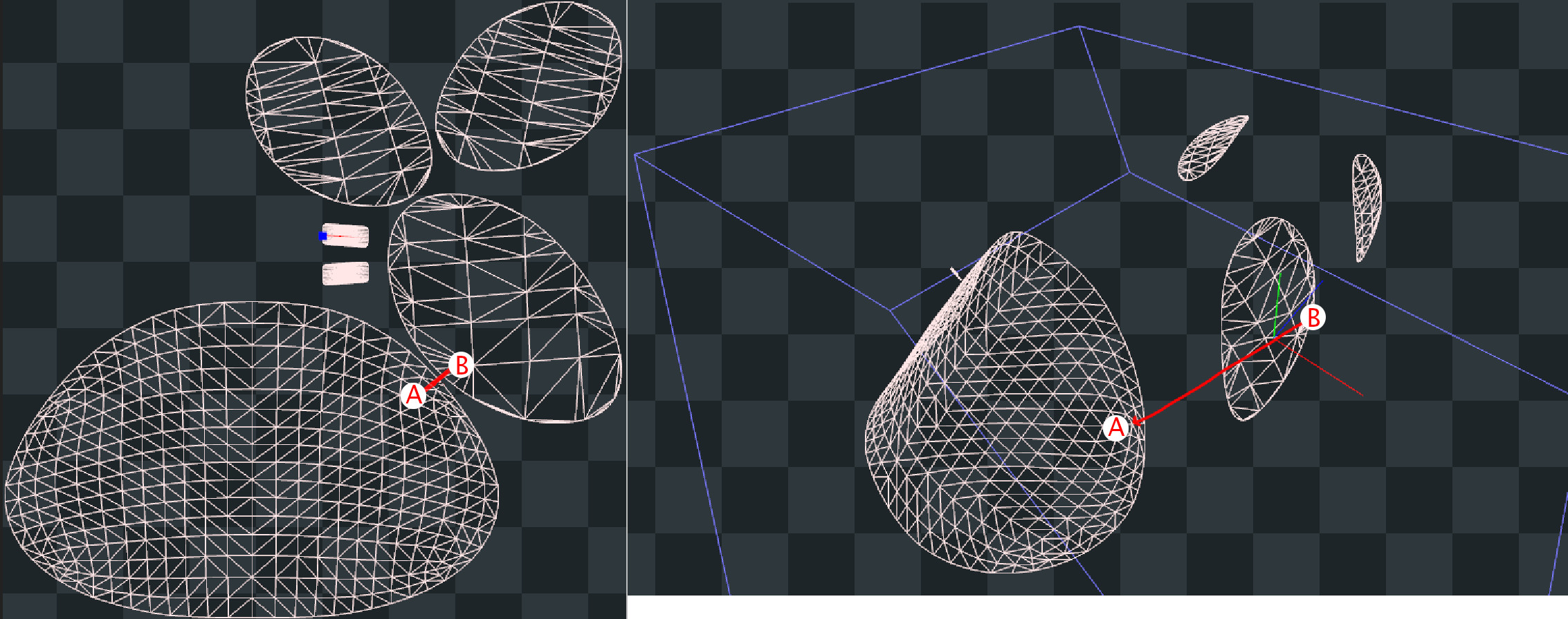
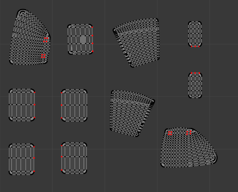
Regarding UV island packing, each flight loop, the rain algorithm calculates the velocity, direction and momentum of the raindrop in 3D space and then animates its translation on the 2D texture accordingly for the next flight loop. The algorithm knows when a raindrop is within the bounds of a UV island, so when a raindrop has been calculated to move outside of any UV island, then the raindrop ceases to exist. If your UV islands are packed close enough together, then the speed and momentum of the raindrop may be enough where the raindrop “jumps” from one UV island to an adjacent one in 2D space during one flight loop calculation. This effect is illustrated in the screenshots below on the default Lancair Evolution.
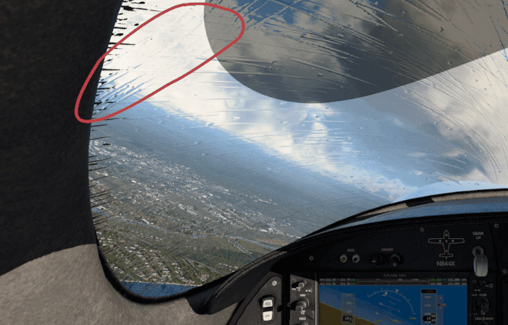
On the UV map (left side), the window uv islands are placed very close together, but the physical 3D locations of the window elements (right side) are not that close together, so in reality, a raindrop would not instantly jump from point A to point B as shown below, yet because the UV islands are close together, the algorithm may animate the raindrop as if this is what happened. If your UV islands are not aligned in a natural way, then a “jumping” raindrop could appear to change directions as its momentum carries it into the adjacent UV island, but with the direction vector from the previous UV island. The red circle in the image further below shows the undesired result of such a situation.
There are three ways to avoid this unwanted effect:
1. Use TRIS_break Directive (12.1+ only)
This is the preferred method for projects supporting X-Plane 12.1+ only. It allows for maximum UV island packing efficiency. If using this method, then each individual window should be separated to be its own mesh object in Blender. If using XPlane2Blender V4.3+, then on each window mesh, enable the “Rain Cannot Escape” checkbox_**.**_ The TRIS_break directive will then be applied to each window mesh. The image below shows the checkbox option and the typical results in the OBJ file.
The TRIS_break directive is a ‘separator’ between TRIS commands and does not need to exist both before and after a TRIS entry in the OBJ file; however, Xplane2Blender may put extra TRIS_break directives before and after some TRIS commands, which is fine. If you are manually editing the OBJ file, just know that a single entry between your rain glass TRIS is all that is required to prevent ‘raindrop jumping’ between those TRIS groups.
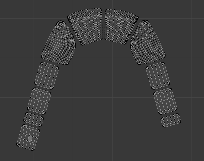
2. Align UVs in a Natural Way
If you want to pack your UV islands tight, get good visual results, and still support X-Plane versions prior to 12.1, then you can align your UV islands so that if a raindrop is moving fast enough that it migrates from one UV island to the next in a single flight loop, then it will be moving in a consistent direction between the UV islands. The example below shows how such UV islands might be aligned. If using this method, then each window does not need to be separated into its own mesh object, all windows can be part of a single Blender mesh object. This method is not recommended for large rainglass texture sizes! as it wastes too much textures space and VRAM. The better solution for pre 12.1 rainglass support is to pack your UV islands just tight enough to avoid raindrop “jumps” (method 3 below)
3. Spread out your UV Islands
The third option is to spread out your UV islands as required, orienting each island any way you like as long as they’re just far enough apart where a raindrop is unlikely to translate from one UV island to another in one flight loop calculation. As raindrops move outside a UV island, they cease to exist. Again, this method wastes some texture space similar to method 2 above, but not as much. As with option 2 though, the windows do not need to be separated into their own mesh objects. This is the better method if you want to support XP version before 12.1.
Windshield Friction (12.1+ only)
Different windshields might have different coatings applied to them to affect how rain interacts with them. For example, on aircraft with blowers, the windshield tends to be coated with a highly rain repellant material to avoid rain drops accumulating or streaking over them. Likewise, some aircraft also have the option to apply rain repellant during the flight to decrease glass friction. Starting with X-Plane 12.1.0, this can be modelled using the following GLOBAL directive in the OBJ header section.
RAIN_friction <some/dataref/and/default_is_1>
The dataref lets you adjust the friction dynamically at runtime, although most aircraft will probably just use a fixed value as this is not a common option on aircraft glass. Decreasing the value will decrease glass friction and also decrease the likelihood of rain drops becoming streaks.
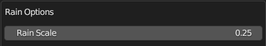
Rain Drop Size / Scale
X-Plane creates rain drops with a default, unitless size of “1” and depending on the texel resolution of your UV islands, the rain drops may need to be scaled up or down for your application to look more plausible. The scale of the raindrops may be altered to be bigger or smaller via an OBJ Global Directive, “RAIN_scale”. This scaling factor can be set via the Collection Properties Panel. This value is typically set after testing in X-Plane using the Rain Inspector Tool described next.
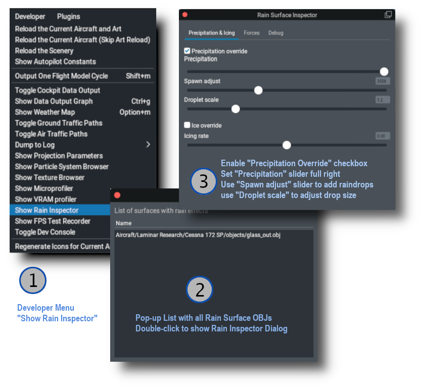
Rain Inspector Tool
X-Plane has a tool to debug Rain Effects in sim. This tool was developed for internal Laminar use but proved useful enough to make available to the public. Being an internal tool, it has several settings you will not need to be concerned with. This tool allows for quick testing of the rain effects without having to change X-Plane’s weather settings. The image below shows the sequence for use. If you have configured your OBJs to be rain glass/inside_reflector, you will see the rain effects in X-Plane as you make adjustments to the Spawn and Scale sliders. Note that its typical to run your test on the Outside Rain Glass OBJ only since that is the only surface exposed to the rain.
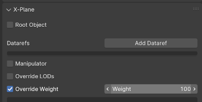
Be sure you check the rain effects from both inside and outside the aircraft. If you have any translucent sun visors, then make sure you can see raindrops through those as well. If you cannot, then make sure your sun-visor meshes are part of your Inside reflector OBJ and also that your sun-visor meshes have been configured to draw last within the OBJ by using XPlane2Blender’s “override weight” option on the object property Tab as shown below. Mesh objects assigned a weight value will draw in the order of their Weight values, with the highest weight value mesh objects drawing last.
3D Windshield Wiper Effects
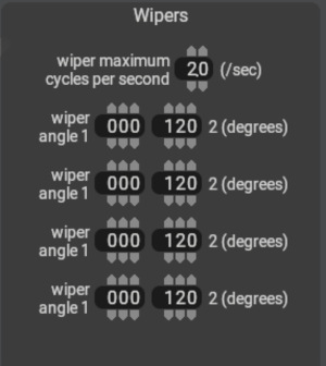
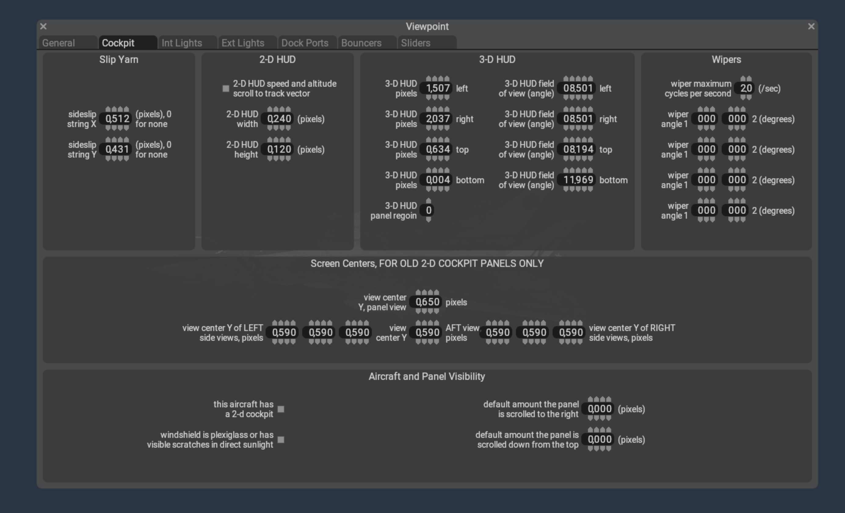
If your aircraft have 3D windshield wipers, you will first need to configure the periodic timing of the wipers in PlaneMaker via the Standard Menu > Viewpoint > Cockpit Tab > Wipers panel as shown in the example screenshot below.
In this panel, you specify the limit angles of the wiper travel (usually 0º to some max valueº) and their oscillation frequency. These fields establish the range of values of the four wiper angle datarefs below, which can be used to drive your 3D wiper animations as well as the 2D wiper effects.
// Dataref to turn on the wipers
sim/cockpit2/switches/wiper_speed_switch    // 0 = park,    1 = 25%speed,   2 = 50%speed,    3 = 100%speed.

// Datarefs for the Instantaneous Angle of the wiper arms
sim/flightmodel2/misc/wiper_angle_deg[0]
sim/flightmodel2/misc/wiper_angle_deg[1]
sim/flightmodel2/misc/wiper_angle_deg[2]
sim/flightmodel2/misc/wiper_angle_deg[3]
Since the raindrop animations happen in 2D texture space, and windshield wiper animations exist separately in 3D space, then we need a way for the 2D rain algorithm to know where your 3D wiper blades are on the window so the effects are in sync. You don’t want the 2D rain wiper algorithm wiping away raindrops behind or ahead of your 3D wiper blade, so timing the 2D effect with your 3D animation is critical.
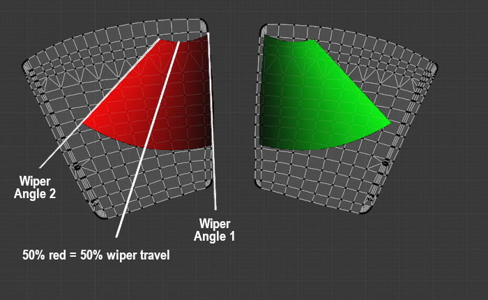
The 2D wiper position reconciles with the 3D position through the use of a dedicated “wiper gradient texture”, with colored gradient regions that represent the area swept by the 3D wiper blades across the UV islands. The color black represents one extreme position of your wiper travel (0% / wiper angle 1) and a fully saturated color channel (100% red / green / blue / alpha(white)) represents the other extreme position of your wiper travel (wiper angle 2). The example below shows how these swept gradient regions overlay the UV islands of windows as well as how the gradient values represents wiper travel.
Because we use a single image with four channels (RGBA) to contain the wiper data, this means we can simulate up to four independently controlled wiper blades per OBJ, but most of the time there’s just one or two. The image below shows what a typical wiper texture looks like for two independently controlled wipers where RED = wiper 1, GREEN = wiper 2. (BLUE = wiper 3, Alpha = Wiper 4, neither of which are used below). Note that if both wipers were controlled together by a single dataref (wiper 1), then both wiper gradients would be RED.
If your windshield wiper animation is completely linear, i.e. you only have two keyframes at the extreme positions, then the gradient texture would also be completely linear along its arc and you might could paint this texture by hand with some deft software ninja skills, but its not always as easy as it may appear and getting the gradient exactly right so the wiper effect matches the 3D wiper position can be a challenge. Fortunately, XPlane2Blender has a solution for us! The “Bake Wiper Gradient Texture” tool.
Wiper Gradient Texture Baking
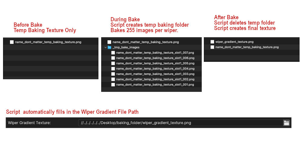
This tool will automatically create your Gradient Wiper Texture for you by using your 3d animation to generate the 2D wiper texture. In general, you’ll create a temporary ‘baking texture’, input/set multiple parameters in Blender, begin the bake, and during the bake process, the script will create a temporary folder and bake 255 temporary images per wiper. After that baking step, the script will then use those temporary images to create the final wiper texture, save it and delete the temporary folder. The baking process can take a while depending upon your machine capabilities, bake settings and texel densities. The single wiper example shown below was done on a Mac M1 laptop and took approximately 12 minutes total with a conservative texel density. Higher texel densities will increase bake times.
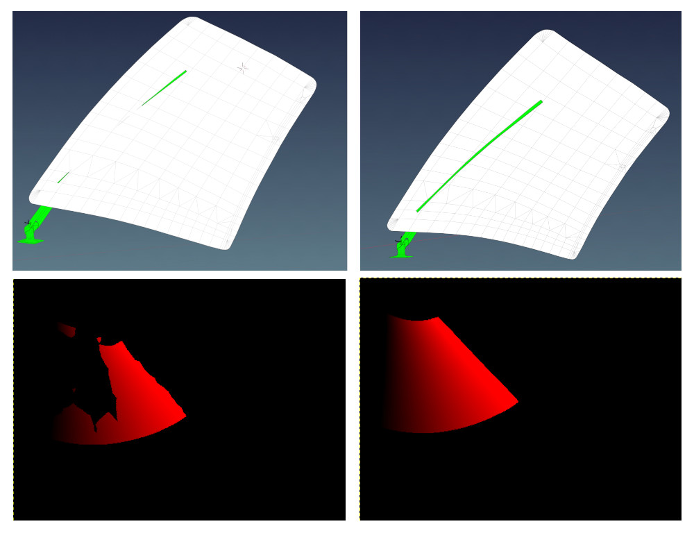
💡 IMPORTANT: For usable results, the wiper blade and windshield need to be in “collision contact” throughout the animation, i.e. the blade penetrates THROUGH the windshield mesh. If not, you may end up with areas on the UV island that are not calculated properly and you will get blotchy results. The image below shows the difference in results with partial intersecting geometry (left side) vs. fully intersecting geometry (right side). Its common to duplicate a blade temporarily and reshape / extend it through the windshield just for the gradient bake and then discard it after.
There’s a lot of steps in the baking process, so we’ll just dive right in via a step-by-step checklist:
Make sure ‘Cycles’ is the active renderer. It will not work with Eevee or Workbench.
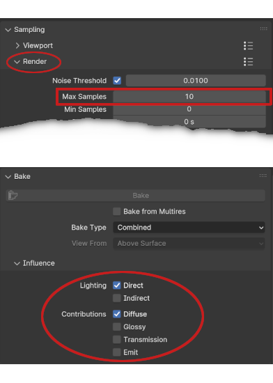
Set your Cycles Render samples (not Viewport) to a low number, like 10, and set your Lighting and Contributions check boxes as shown below. (Blender 4.1 shown). This will reduce baking time.
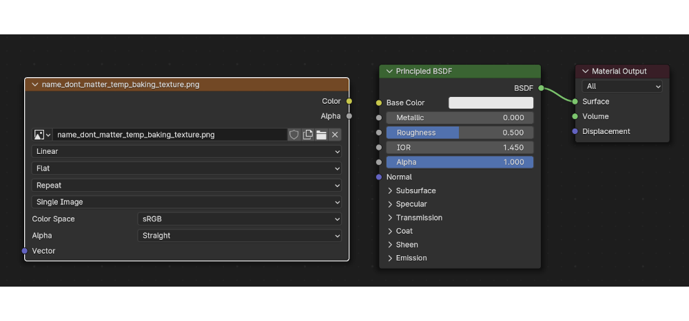
A four channel (RGBA), 8-bit per channel (32 total) “temporarybaking texture” must exist beforehand. Create, name and save an empty PNG the same size as your final texture, any filename will work. If you use Blender’s Image>New menu to create the image, do NOT select the ‘32-bit Float’ checkbox option, this results in 32-bits per channel, not 8 and will prevent the bake.
You can put this temporary texture anywhere you like for the bake, but we recommend putting it in the same location where you normally keep your other OBJ textures because the script will automatically create the final wiper gradient texture in this same location AND automatically enter the file path in the “Wiper Gradient Texture” text field for you (overwriting any existing entry). If you move the wiper gradient texture to some other final location after the bake, you will need to adjust the file path so it gets written to the OBJ header correctly.
Add an Image Texture Node to your rainglass material, and select the temporary baking texture you created in the previous step. The wiper script leverages Blender’s baking workflow and gets the file path to the baking texture from this image texture node. Unlike a regular Blender bake however, the image texture node need NOT be selected to bake, but does not matter if it is. Below is an example of an image node with the temp baking texture selected.
Animate your wiper motion over 255 frames (required). You can begin at any keyframe ≥ 1, but your last keyframe needs to be (Begin keyframe + 254). So if you begin your animation at keyframe 1, then your last keyframe will be 255. If you begin at keyframe 16, your last keyframe is 270, etc. The baking UI dialog allows you to specify the first keyframe value and Xplane2Blender will add 254 to it. The default begin keyframe is 1, we recommend you stick with that. You can use as many intermediate keyframes as is required for your animation. TIP: If you have already animated your wipers, but not over 255 frames, then note that Blender’s scale(S) command works on keyframes! Set the animation playhead on your first keyframe, select all keyframes for your wipers, hit ‘S’ and simply scale all your keyframes until the last one is 254 frames after the first one.
If you want to bake all wiper regions at the same time, then combine all window mesh objects that have wiper effects into a single mesh object (CTRL-J) for the bake. Give the mesh object (in the outliner) a unique name, e.g. wiper_windows. After the bake, you can separate out the mesh islands if need be, for example if you’re using TRIS_break option on each mesh object. You can also bake each wiper region separately if you want to and combine the images manually, i.e. you need to rebake one window only.
To shorten the bake time further, you can separate out the wiper BLADE mesh only (the part that touches the window). The fewer polygons involved in the calculation, the better. Give the wiper mesh objects that intersect the windows unique names (in the outliner) such as:
right_wiper_blade
left_wiper_blade
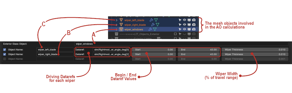
Now its time to enter all the pertinent data into the Rain Options panel (Scene Tab Collection Settings). Note that if your “Wiper Texture Gradient” text field is empty (the script will fill it in after the bake), then the wiper UI elements may appear grayed out; however, this is simply visual and you can still enter information in them. You will be manually entering mesh object names (from the outliner) into the Wiper settings text fields. If you misspell the name, the script will let you know with an error pop-up when you try to bake. In the example screenshot below, Item A is the Exterior Glass Object with wiper effects. Item B is a wiper blade mesh and Item C is a second wiper blade mesh. These fields tell the script which mesh objects to include in the baking process. If you have more wiper blades, just enable the bottom checkbox to enter their data. The example below will bake two wiper gradient regions to the RED and GREEN channels of the gradient texture.
NOTE: Each time you enable a checkbox, a new one will appear, up to 4 total. In the Object Name text box, enter the name of the Wiper Blade Mesh Object. Confirm name in Outliner. The first wiper will be Wiper 1 (red), the second Wiper 2 (green), etc, etc.
Enter the name of the driving datarefs for each wiper and keyframe values. This data will get written to the OBJ file. Common datarefs are:
sim/flightmodel2/misc/wiper_angle_deg[0]
sim/flightmodel2/misc/wiper_angle_deg[1]
The following two items are required in order for the Bake Wiper Texture Gradient button to activate.
The collection with the rainglass meshes must be enabled for export on Blender’s Scene Tab.
The collection with the raingless meshes must be selected in the outliner.
Time to Bake! On Blender’s Render Properties Tab, and with the above two criteria met, the “Bake Wiper Gradient Texture” button should now be active. Press the button to begin the bake. The image below shows the sequence of the Gradient Texture Baking Process.
A few things to note about the bake process:
During the bake, you will not see any animation in the 3D viewport. The wipers will not move. Blender is essentially “frozen” with no progress indicator, so don’t plan on doing any work in Blender while the bake is going on.
You can monitor the progress by observing the contents of the ‘__tmp_bake_images_’ folder, which will be growing with files as the 255 images (per wiper) are baked. Do expect 10+ minutes per wiper channel.
Once all images are baked, there will be a period of time with no apparent activity as the script calculates and assembles the final gradient image.
When complete, the temporary folder will be gone, the “wiper_gradient_texture.png” file will be in the folder and Blender will be functional again.
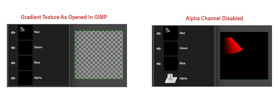
💡 NOTE: The script writes to all four image channels (RGBA) regardless of how many wipers are configured. If baking less than 4 wipers, the alpha channel will be completely black and as such, the RGB channels will be transparent when you open the image; however, the color information for the baked channels is present as can be seen below. Disabling the alpha channel will reveal the RGB channels.
Exporting and GLOBAL Settings
After exporting your rainglass object, the rain settings will be present in the GLOBAL properties of the OBJ as shown below. The default 737 example below has two independently controlled wipers, a custom rain scale and one wiper gradient texture. Remember that the wiper baking script will auto-name the baked texture, “wiper_gradient_texture.png”, but you can rename it to anything you like. If you do rename it, then make sure you also change the filename in XPlane2Blender’s “w_iper gradient texture_” text input box. Its good practice to check the exported OBJ to make sure all the settings and filepath are as expected.
Ground power provides electrical power to a parked aircraft, so its systems can be operated without depleting the battery even if the engine(s) are turned off.
The ground power plug must be plugged into the aircraft first, then a relay can be closed to actually connect an electrical bus to the external power source.
Plugging the power in
Aircraft made for X-Plane 12.07 and earlier always have voltage on the ground power receptacle if the aircraft is stationary (ground speed is less than 1 knot).
Aircraft made for X-Plane 12.0.8 need to call for ground services to have the ground power plugged in. In order to that, preconditions must be met:
The aircraft must be stationary (ground speed less than 1 knot)
The aircraft must not be on a runway (it needs to be on a ramp or taxiway area, or on grass)
Then, the user can request to “service the aircraft”. This will cause power to become available. Whether an animated ground power unit will show up in the 3d world to service your aircraft depends on
the aircraft author must have specified a location for the generator cart to be parked relative to this aircraft. That’s in Plane Maker, in the “dock ports” tab, “has ground power cart” must be checked and the coordinates specified
the airport must have a route for ground service vehicles to reach your aircraft parking position
In the absence of the above, the electrical power will still work, but no animated generator cart will be visible.
Making contact
Once the power is available, the available voltage will be readable in the sim/cockpit2/electrical/GPU_generator_volts dataref. If this reads 0, nothing is plugged in. This information can be used by aircraft to power “hot buss” items that might be available even before the switch in the cockpit is activated. This can also be used to indicate the availability of ground power to the pilot, such as the switch lighting up.
Now, the dataref sim/cockpit2/electrical/GPU_generator_on can be used to switch the GPU relay to on. Now, all connected busses will be powered from GPU power, all equipment can be used and the batteries will be getting charged.
Third-party overrides
At some third-party scenery airports, or with some aftermarket aircraft, the use of X-Plane default ground services might be undesirable. For these, the ground power can be overridden by plugin logic, so the third party product can decide ground power availability rather than X-Plane’s ground service system.
To take control of the GPU power, the plugin needs to set sim/operation/override/override_GPU_volts to 1 and then write the desired voltage to sim/cockpit2/electrical/GPU_generator_volts or 0 if the GPU isn’t supposed to be plugged in right now.
In order to not fry any virtual circuits, the plugin should check the dataref sim/aircraft/electrical/acf_nom_gen_volt to find out whether the user aircraft expects 12V, 28V, 110V or anything else.
X-Plane 12 features a 3-D HUD – besides drawing HUD markings on top of the 3-d scene, the HUD aligns to the world in 3-d with the same parallax error that a real HUD would have, and looks “far away” to a user in VR.
The HUD consists of three separate authoring elements:
An area of the aircraft’s 3-d panel texture that has HUD markings.
A 3-d mesh in an aircraft attached object with appropriate objects, that will serve as the HUD glass. The HUD image will only appear when the glass covers the screen space area in front of where the pilot “perceives” the HUD to be.
Plane-Maker settings to calibrate the 3-d HUD’s alignment.
Setting Up the HUD in Plane-Maker
Plane-Maker’s viewpoint cockpit screen contains a section “3-D HUD” that requires three types of information:
The field of view angles of the edge of the HUD glass. You may need to calculate these in your 3-d model – it is the number of degrees to the left, right, up and down from from the pilot looking straight ahead at the default pilot viewpoint.
The pixel position on the 3-d texture panel that the HUD image will be taken from. The lower left is 0,0, and the unit is pixels. You will be able to see this rectangle in the panel editor to validate that it is correctly set up, but it must be changed in the viewpoint cockpit screen.
The panel region. If your 3-d cockpit uses panel regions, pick the region number for the HUD here. If your aircraft does not use panel regions, you should leave this as the default “0” value.
Creating the HUD Graphics
In the 3-d panel editor, click the HUD icon in the upper right button bar (just to the left of the “2-D” icon) to view the HUD preview lines. If the panel is set up with a 3-d HUD, you will see:
A cyan box showing the edge of the HUD’s image and
A HUD ladder showing the horizontal center, horizon, and 2.5 degree vertical increments.
You can use these queue marks to calibrate your HUD graphics.
⚠️ WARNING: as of X-Plane 12.0.8 the “2-d” HUD instruments only work in the 2-d HUD, and the “3-d” HUD instruments only work in the 3-d HUD. We recommend using generic instruments for the 3-d HUD.
Setting Up the 3-d HUD Object
The 3-d HUD needs a glass element in an object, with a special attribute
    ATTR_hud_glass
    TRIS	36 18
    TRIS	54 18
  ATTR_hud_reset
Steps to Debug The HUD
First, confirm the HUD image is present by using the texture browser to view the night panel texture.
Second, confirm the HUD glass is present by temporarily removing the HUD glass attributes and giving it a debug color texture.
Auto-coordination helps users with no hardware rudder pedals fly airplanes when rudder input is required for coordinated turns, to help with asymmetric thrust conditions and to help with crosswind take-offs and landings.
Which aircraft get auto-coordination
Auto coordination is applied only to aircraft, not rotorcraft. For successful operation of a helicopter it is absolutely necessary to have means of operating the anti-torque pedals, through pedals or a twisting joystick.
When is auto-coordination active?
Auto-coordination is active whenever no joystick axis is configured for the “Yaw” input. If actual pedals or a joystick with twist-grip is connected and the axis assigned, auto-coordination will never be applied.
If a plane is equipped with a Yaw Damper and it is turned on by the pilot, has power and is not failed, auto-coordination is not applied, regardless of joystick configuration. The yaw damper is relied upon for coordinated turns and auto-coordination does not interfere with it. Note that that requires the yaw damper to be configured. In testing, we found a number of published aircraft that had yaw damper switches in the cockpit but no configured yaw damper, so the switch would not do anything. In that case (the yaw damper constants being all zero), the yaw damper switch position is ignored as it is a dummy. Please consult the article on autopilot constants to learn how to configure the yaw damper if your airplane needs one.
Auto-coordination for X-Plane 11 aircraft
X-Plane 11 aircraft loaded in X-Plane 12 get the exact same rudder assist as in X-Plane 11. A proverse rudder input of 20% of the aileron input is applied when the user deflects the aileron. No assistance is provided for crosswind or asymmetric thrust.
Auto-coordination for X-Plane 12 aircraft
Aircraft authored with Plane Maker 12 allow configuration of the auto-coordination controller. The auto-coordination controller is a PID controller that seeks to keep beta (sideslip angle) at 0 degrees. That means, it applies rudder to keep the fuselage aligned with the airflow, and in doing so, it works against adverse yaw and helps with coordinated turns. Keeping the slip angle at 0 however also helps cancel P-factor and spiraling slipstream, so you will notice that the auto-coordination applies right rudder in high-power, high-AoA situations in single-engine propeller aircraft, where right rudder is needed to keep the airplane coordinated in climb, which a simple aileron coupling could not achieve. Note that this also works in single-engine flight of a multi-engine aircraft: With a failed engine in a twin, the auto-coordination will step onto the live engine in an effort to compensate for asymmetric thrust. Note that it tries to achieve zero side slip, not zero ball, i.e. it tries to center a yaw string, not the inclinometer. With OEI it will naturally “split the ball” and require a slight bank into the good engine to fly straight.
The controller is a PID controller that gets the beta angle in degrees as input and acts directly on the rudder, like the pilot would with rudder pedals. The controller gains can be tuned in flight in the Developer->Show Autopilot Constants window, in the “yaw” tab. Note that X-Plane does not save those values permanently, so once a good tuning is established, the values must be saved to the aircraft file in Plane Maker.
The beta angle input into the controller changes smoothly from slip angle to crab angle as the aircraft climbs or descends 5 meters from the surface. This is what allows crosswind takeoffs and landings even with no hardware to perform realistic cross-controlling. In a crosswind landing, the controller will try to eliminate crab angle as the aircraft is flared over the runway. This needs to be anticipated by the pilot who needs to apply slight opposite aileron as the auto-coordination kicks out the crab before touchdown.
Comments Off on Rudder auto-coordination in X-Plane 12
Starting with X-Plane 12 it is possible to independently scale symbols and text of the navdisplay, and also change the relative locations of symbols and labels. Customization of the map display is possible by editing the map_s_HM-1.png, map_s_HM-2.png, map_s_HM-2.png and map_s_HM-4.png graphics and supplying the graphics specific for your aircraft through the library system (the path is cockpit/EFIS/EFIS_maps). These png files can supply alternate symbols, colors or fonts to generate the style of the nav display. Learn more: Navigation Display Scaling
New HUD
X-plane 12 contains a new 3-d HUD system. This system is unrelated to existing tech for a HUD in 2-d panels or in the “forward with HUD” view.
The new HUD works by projecting a region of the 3-d panel in front of the aircraft in the distance, but only drawing it where it intersects a 3-d modeled HUD glass. This simulates the real-world HUD experience of the HUD being focused at infinity (and aligning with the horizon), while only being visible when the pilot’s head is within a specific 3-d box in the aircraft.
To use the new HUD you will need to do three things:
Specify the geometry of the HUD in the Plane-Maker viewpoint screen, cockpit tab, 3-d HUD section. You specify both:
The panel texture area to be used as the HUD (in pixels) and
The angle of the HUD from the pilot’s view (as field of view ratios).
Build the HUD image in your 3-d panel in the appropriate area.
In one of your objects marked interior glass, use the new ATTR_hud_glass to mark the glass that the HUD “appears on” and make sure that that OBJ is in the “glass reflective” light group in X-Plane.
To calculate the FOV ratios, use the trigonometric tangent function for the angle from center for each side. So for example, a HUD with 20 degrees below the horizon and 10 degrees above would have an FOV ratio of tan(-20) and tan(10) or -0.364 for the bottom and 0.176 for the top.
For an example of the 3-d HUD, see the F14.
OPEN ISSUE: as of this writing, the HUD light levels are not correctly set. Future guidance will come when this issue is resolved.
Plane Maker Updates
Airframe and Tail Anti-Ice and De-Icing boots
X-Plane 12 treats the tail surfaces different from the wing surfaces when it comes to ice accumulation and anti- or de-ice measures. Learn more: Airframe and Tail Anti-Ice and De-Icing boots
Autopilot
Navigation Source
This article summarizes X-Plane’s capabilities when it comes to modern integrated approach navigation and sheds light on the new datarefs: Autopilot Navigation Source
Autopilot VNAV modes
X-Plane knows two different types of VNAV, which can be described as “GA” and “Airliner”-type VNAV. The main difference is the availability of auto-throttle. “GA” without auto throttle can only do geometric descents – the vertical path is controlled by the autopilot, while the pilot controls the speed by the throttle (or speedbrakes). “Airliner” with auto-throttle uses the auto-throttle to set climb power in climb, hold the selected cruise speed in cruise, and comply with speed restrictions (if physically achievable) in descend.
If your aircraft requires rudder pedal input to operate realistically (especially single engine propeller aircraft and light twins) consider configuring the constants for the new auto-coordination to improve the experience for users with no rudder hardware.
Directional Gyro
X-Plane 12 changes the way directional gyro drift is calculated and the behavior of the directional gyro drift data refs. If your aircraft or plugin adjusts or watches these datarefs, you will want to check whether your code still works with the new drift. Learn more: Directional gyro drift and adjustment datarefs
FADEC Controlled Engines
X-Plane can limit the power output of altitude engines (or flat-rated engines) in order to not overtemp or overtorque them. In addition to thrust or torque limiting, X-Plane 12 can also limit to N1 or EPR values. Learn more: FADEC controlled engines
Flight Control Trim
If your aircraft is configured to have a trimmable horizontal stabilizer, there is no change in behavior from X-Plane 11. X-Plane 12 allows for three distinct ways of trimming the flight controls, and allows assigning different types of trim to different axes, so it is possible to have a trim tab on the elevator, but a pre-loaded centering spring on the rudder, as is common with many general aviation aircraft like the Cessna 182. Learn more: Types of flight control trim
Flight Control Splits
In case of a flight control malfunction where a jam occurs in one system, it is usually possible to split the controls, in some aircraft by pulling a flight control disconnect handle, in others the torque tube shears when a certain (high) load is applied to it. X-Plane simulates both the type of failure and the flight control split to deal with it. Learn more: Flight Control Splits
Helicopter Governors
X-Plane 12 revises the interaction of collective and throttle control in helicopters. Existing helicopters retain the default behavior of X-Plane 11 until modified in Plane Maker 12 to opt into one of the new governor systems. The joystick control assignments for collective and throttle don’t change, but there’s a new joystick curve available for Robinson-style throttle control. Learn more: Helicopter governor and correlator configuration
Hydraulic systems
X-Plane has three hydraulic systems per aircraft that can power a variety of actuators. Most notably, each flight control surface can be powered by any combination of hydraulic actuators. Learn more: Hydraulic systems and flight controls
Gear systems
If you have a three-position gear switch (Up-Off-Down) that you are using custom scripting/animation for, consider checking the new default option: Hydraulic gear systems
Moment of Inertia/Radii of Gyration
If you have customised the radii of gyration to achieve a “more heavy/stable” feel for your aircraft, consider switching to actual payload stations instead to achieve dynamic moment of inertia calculation based on actual load-out: Weight & Balance and Load Stations
Idle speeds
Setting up idle speed is a three-step process:
1. Getting the internal friction right
2. Setting the right amount of throttle to overcome the internal friction
X-Plane 12 differentiates between pilot & copilot sides for cockpit animations, joystick hardware, and plugins. Learn more: Pilot and Copilot Flight Control Inputs
Propeller overrides
X-Plane features datarefs that let you override parts of the flightmodel. While these datarefs are often named for the dataref whose value you control when the override is enabled, they really act by removing logic blocks from X-Plane’s flight model and systems simulation. Learn more: override_prop_pitch and override_prop_mode
Single Spool Engines
Aircraft that were using single spool engine types and relying on X-Plane to convert these to double spool engines should correct the engine type to “jet 2 spool” in Engines Specs > Engines 2 tab, then double check performance.
Stabilizer Trim and Servo
X-Plane provides two ways to trim the elevator or stabilizer of a plane: Mechanical or with an electric servo. The presence of an electric servo has consequences to the type of commands you can use to move the trim, and the commands you want to set up for hardware. This article explains the interaction of the commands and X-Plane systems code: Stabilizer Trim and Servo
Windshield ice and rain protection
X-Plane 12 simulates more than one glass surface for looking out. This affects how new 3D rain, icing, defrost, and wipers behave. Learn more: Windshield ice and rain protection datarefs
Radios and Navigation
Changes have been made to standalone DME, TACAN stations, and WAAS reception. Learn more: Changes to Radio Navigation
Weapons
Master Arm
In X-Plane 11 and earlier, the “master arm” command and panel switch had no effect on the sim. In X-Plane 12, master arm now functions: when the master arm switch is off, the only weapons that will fire are flare and chaff. When the master arm is on, weapons will fire based on their prior selection rules, e.g. if they are either selected in the weapon console or by the various individual arm/disarm datarefs by weapon type.
A new writable dataref sim/cockpit2/weapons/master_arm provides writable access to the switch position.
For compatibility, aircraft are loaded with the master arm switch on, so existing aircraft without a master arm switch will have functioning weapons. If you have this switch you can initialize it to off in a flight-initialized plugin callback.
Sound
FMOD 2.02
X-Plane 12 now runs FMOD 2.02, and while your older, already compiled sound banks will still work on X-Plane 12 with no changes, the workflow for new projects has a few caveats. Learn more: FMOD 2.0 upgrade notes.
X-Plane features datarefs that let you override parts of the flightmodel. While these datarefs are often named for the dataref whose value you control when the override is enabled, they really act by removing logic blocks from X-Plane’s flight model and systems simulation. This article explains the exact effects of overriding the prop_pitch and prop_mode overrides.
Prop Modes In X-Plane for Constant RPM Props.
X-Plane’s prop model features four prop modes for constant-RPM props in sim/flightmodel2/engine/actuators/prop_mode:
Feathered (prop_mode = 0): the prop goes to its feathered pitch as set in the .acf file.
Alpha range (prop_mode = 1): this is normal operation – a target RPM is set with the blue prop levers. This is visible via sim/cockpit2/engine/actuators/prop_rotation_speed_rad_sec. The governor tries to adjust pitch within the range of the min and max pitch as set in Plane-Maker to maintain commanded RPM if possible.
Beta range (prop_mode = 2): prop pitch is commanded directly with the throttle as it moves through the beta range – the engine is at idle and the prop angle changes. On some planes the prop may even go into a reverse range while in beta mode – this is set in Plane-Maker.
Reverse range (prop_mode = 3): prop pitch is commanded directly with the throttle and goes from the beta pitch to reverse pitch, and throttle commands the actual throttle. This can be used to simulate reverse-by-throttle or a range of reverse angles or both.
X-Plane will set the prop target speed with the prop joystick axis if assigned, and the throttle with the throttle axis if assigned. The prop mode is set between reverse/beta/alpha by commands, and feathering happens via a series of on-board systems, e.g. feather when mixture is pulled, auto-feather, or feather when the prop lever is pulled past a detent.
Overriding prop_mode
When sim/operation/override/override_prop_mode is set to 1, X-Plane will not move the prop mode between alpha, beta and reverse when (1) the panel 2-d throttles are dragged or (2) a joystick axis moves into a new range on an aircraft with beta and reverse ranges built into the throttle. (This is a .acf setting.)
X-Plane will change modes if you write to the dataref or when commands like sim/engines/thrust_reverse_toggle and sim/engines/beta_toggle are run; to ensure complete control of the dataref, override commands that affect beta or reverse.
When prop_mode is overridden and prop_pitch is not overridden, X-Plane will control feathering automatically, and writes of 0 to the prop_mode will be rejected. Automatic feathering in the sim will still work.
Overriding prop_pitch
When setting sim/operation/override/override_prop_pitch to 1, X-Plane will not change the prop pitch. A bunch of code is bypassed:
The joystick prop axis will not set the prop pitch (for variable pitch props) and will not set the target RPM (for constant RPM props). You must read the axis yourself using sim/joystick/joy_mapped_axis_avail and sim/joystick/joy_mapped_axis_value – array index 8 for a single global prop lever or 24-27 for individual prop levers.
Constant mach and thrust-vectored props will not auto-adjust the target RPM.
Feathering is disabled; you must set the prop mode to feather, and you must set the actual prop angle. Setting a prop mode of 0 and not setting the angle will not result in feathering!
Constant RPM props will not set their pitch.
You can set the prop angle directly via sim/cockpit2/engine/actuators/prop_angle_degrees.